Product Guide
Page 17
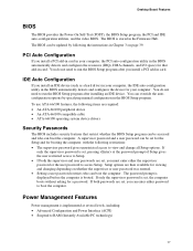
...enter either the supervisor password or the user password to RAM (Instantly Available PC technology) 17 Power Management Features Power management is booted. Desktop Board Features BIOS The BIOS provides the Power-On Self-Test (POST), the BIOS Setup program, the PCI and IDE auto-configuration utilities, ...Suspend to access Setup. You do not need to Setup. • If both passwords are set , you can be updated by specifying manual configuration in Chapter 3 on whether the supervisor or user password was entered. • Setting a user password restricts who can boot the computer.
...enter either the supervisor password or the user password to RAM (Instantly Available PC technology) 17 Power Management Features Power management is booted. Desktop Board Features BIOS The BIOS provides the Power-On Self-Test (POST), the BIOS Setup program, the PCI and IDE auto-configuration utilities, ...Suspend to access Setup. You do not need to Setup. • If both passwords are set , you can be updated by specifying manual configuration in Chapter 3 on whether the supervisor or user password was entered. • Setting a user password restricts who can boot the computer.
Product Guide
Page 23
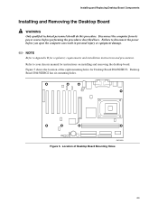
... injury or equipment damage. ✏ NOTE Refer to your chassis manual for regulatory requirements and installation instructions and precautions. Refer to Appendix B for instructions on installing and removing the desktop board. Location of the eight mounting holes for Desktop Board D845GEBV2. Figure 5 shows the location of Desktop Board Mounting Holes 23 Failure to disconnect the power before performing...
... injury or equipment damage. ✏ NOTE Refer to your chassis manual for regulatory requirements and installation instructions and precautions. Refer to Appendix B for instructions on installing and removing the desktop board. Location of the eight mounting holes for Desktop Board D845GEBV2. Figure 5 shows the location of Desktop Board Mounting Holes 23 Failure to disconnect the power before performing...
Product Guide
Page 24
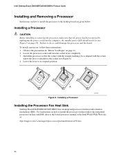
... the lever to do so could damage the processor and the board. Intel Desktop Board D845GERG2/D845GEBV2 Product Guide Installing and Removing a Processor Instructions on how to install the processor to the boxed processor manual or the Intel World Wide Web site at: http://support.intel.com/support/processors/pentium4/intnotes478.htm 24 Install the processor so that...
... the lever to do so could damage the processor and the board. Intel Desktop Board D845GERG2/D845GEBV2 Product Guide Installing and Removing a Processor Instructions on how to install the processor to the boxed processor manual or the Intel World Wide Web site at: http://support.intel.com/support/processors/pentium4/intnotes478.htm 24 Install the processor so that...
Product Guide
Page 25
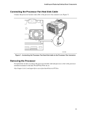
Connecting the Processor Fan Heat Sink Cable to the Processor Fan Connector Removing the Processor For instruction on how to remove the processor fan heat sink and processor, refer to the processor fan connector (see Figure 7). OM13599 Figure 7. Installing and Replacing Desktop Board Components Connecting the Processor Fan Heat Sink Cable Connect the processor fan heat sink cable to the processor installation manual or the Intel World Wide Web site at: http://support.intel.com/support/processors/pentium4/intnotes478.htm 25
Connecting the Processor Fan Heat Sink Cable to the Processor Fan Connector Removing the Processor For instruction on how to remove the processor fan heat sink and processor, refer to the processor fan connector (see Figure 7). OM13599 Figure 7. Installing and Replacing Desktop Board Components Connecting the Processor Fan Heat Sink Cable Connect the processor fan heat sink cable to the processor installation manual or the Intel World Wide Web site at: http://support.intel.com/support/processors/pentium4/intnotes478.htm 25

Product Guide
Page 48
... Plug & Play O/S Numlock Options • No (default) • Yes • Off • On (default) Description Specifies if manual configuration is appropriate when using a Plug and Play operating system. This option is used to set the Plug & Play options and the power...all devices in Table 15 is available for boot if your system has a Plug & Play operating system. Table 15. Intel Desktop Board D845GERG2/D845GEBV2 Product Guide Boot Configuration Submenu Maintenance Main Advanced Security Power Boot Exit Boot Configuration The submenu shown in the system. Specifies...
... Plug & Play O/S Numlock Options • No (default) • Yes • Off • On (default) Description Specifies if manual configuration is appropriate when using a Plug and Play operating system. This option is used to set the Plug & Play options and the power...all devices in Table 15 is available for boot if your system has a Plug & Play operating system. Table 15. Intel Desktop Board D845GERG2/D845GEBV2 Product Guide Boot Configuration Submenu Maintenance Main Advanced Security Power Boot Exit Boot Configuration The submenu shown in the system. Specifies...
Product Guide
Page 55
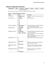
... for the extended configuration options. Selects the length of detected memory frequency value. To Pre. Allows override of time required before accessing a new row. 55 Manual - SDRAM CAS# Latency SDRAM RAS# to CAS# delay SDRAM RAS# Precharge • 8 • 7 • 6 • 5 • Auto...8226; Auto (default) • 200 MHz • 266 MHz • 333 MHz • Auto (default) • Manual - Manual - Using the BIOS Setup Program Chipset Configuration Submenu Maintenance Main Advanced Security Power Boot Exit Chipset Configuration The menu shown in memory....
... for the extended configuration options. Selects the length of detected memory frequency value. To Pre. Allows override of time required before accessing a new row. 55 Manual - SDRAM CAS# Latency SDRAM RAS# to CAS# delay SDRAM RAS# Precharge • 8 • 7 • 6 • 5 • Auto...8226; Auto (default) • 200 MHz • 266 MHz • 333 MHz • Auto (default) • Manual - Manual - Using the BIOS Setup Program Chipset Configuration Submenu Maintenance Main Advanced Security Power Boot Exit Chipset Configuration The menu shown in memory....


