
Intel Desktop Board D845EPI Technical Product Specification
Page 7
...USB Configuration Submenu 87 4.4.9 Chipset Configuration Submenu 88 4.5 Security Menu ...90 4.6 Power Menu ...91 4.6.1 ACPI Submenu 91 4.7 Boot Menu ...92 4.7.1 Boot Device Priority Submenu 93 4.7.2 Hard Disk Drives Submenu 94 4.7.3 Removable Devices Submenu 94 4.7.4 ATAPI CD-ROM Drives Submenu 95 4.8 Exit Menu ...96 5 Error Messages and Beep Codes 5.1 BIOS Error Messages 97 5.2 Port 80h POST Codes 99 5.3 Bus Initialization Checkpoints 103 5.4 Speaker ...104 5.5 BIOS Beep Codes ...104 Figures 1. Location of the Jumper Blocks 54 11. Add-in Board and Peripheral Interface Connectors...
...USB Configuration Submenu 87 4.4.9 Chipset Configuration Submenu 88 4.5 Security Menu ...90 4.6 Power Menu ...91 4.6.1 ACPI Submenu 91 4.7 Boot Menu ...92 4.7.1 Boot Device Priority Submenu 93 4.7.2 Hard Disk Drives Submenu 94 4.7.3 Removable Devices Submenu 94 4.7.4 ATAPI CD-ROM Drives Submenu 95 4.8 Exit Menu ...96 5 Error Messages and Beep Codes 5.1 BIOS Error Messages 97 5.2 Port 80h POST Codes 99 5.3 Bus Initialization Checkpoints 103 5.4 Speaker ...104 5.5 BIOS Beep Codes ...104 Figures 1. Location of the Jumper Blocks 54 11. Add-in Board and Peripheral Interface Connectors...
Intel Desktop Board D845EPI Technical Product Specification
Page 8
... Menu...76 46. Intel Desktop Board D845EPI Technical Product Specification Tables 1. Specifications ...17 4. Supported DDR DIMM Configurations 22 6. I/O Map ...38 13. ATAPI CD-ROM Connector 47 19. Front Panel Connector 51 28. Wake-up Devices and Events 32 10. Rear Chassis Fan Connector 48 21. Front Chassis Fan Connector 48 24. Safety Regulations ...62 37. Serial Port B Connector (optional 50 26. Product Certification Markings 64 39. Front Panel Audio Connector/Jumper Block 55 31. Supervisor and User Password Functions 72 41. PCI Configuration...
... Menu...76 46. Intel Desktop Board D845EPI Technical Product Specification Tables 1. Specifications ...17 4. Supported DDR DIMM Configurations 22 6. I/O Map ...38 13. ATAPI CD-ROM Connector 47 19. Front Panel Connector 51 28. Wake-up Devices and Events 32 10. Rear Chassis Fan Connector 48 21. Front Chassis Fan Connector 48 24. Safety Regulations ...62 37. Serial Port B Connector (optional 50 26. Product Certification Markings 64 39. Front Panel Audio Connector/Jumper Block 55 31. Supervisor and User Password Functions 72 41. PCI Configuration...
Intel Desktop Board D845EPI Technical Product Specification
Page 17
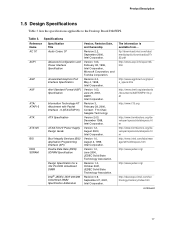
ATX12V BIS DDR SDRAM ATX/ATX12V Power Supply Design Guide Boot Integrity Services (BIS) Application Programming Interface (API) Double Data Rate (DDR) SDRAM Specification Design Specification for a 184 Pin DDR Unbuffered DIMM Intel ® JEDEC DDR 200/266 Unbuffered DIMM Specification Addendum Version 1.2, August 2000, Intel Corporation. Revision 0.9, September 27, 2001, Intel Corporation. ftp://download.intel.com/labs/ media/audio/download/ac97r 22.pdf http://www.acpi.info/spec10b. ATA/ ATAPI...
ATX12V BIS DDR SDRAM ATX/ATX12V Power Supply Design Guide Boot Integrity Services (BIS) Application Programming Interface (API) Double Data Rate (DDR) SDRAM Specification Design Specification for a 184 Pin DDR Unbuffered DIMM Intel ® JEDEC DDR 200/266 Unbuffered DIMM Specification Addendum Version 1.2, August 2000, Intel Corporation. Revision 0.9, September 27, 2001, Intel Corporation. ftp://download.intel.com/labs/ media/audio/download/ac97r 22.pdf http://www.acpi.info/spec10b. ATA/ ATAPI...
Intel Desktop Board D845EPI Technical Product Specification
Page 43
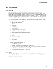
... (ATAPI CD-ROM and front panel audio) Fans Power Add-in boards (PCI) IDE Diskette drive Chassis intrusion • External I/O connectors (see page 50) Serial Port B (optional) Auxiliary front panel power/sleep/message-waiting LED Front panel (power/sleep/message-waiting LED, power switch, hard drive activity LED, reset switch, and auxiliary front panel power LED) Front panel USB (one connector for two ports) ✏ NOTE When installing the board in the load presented by the external devices could cause...
... (ATAPI CD-ROM and front panel audio) Fans Power Add-in boards (PCI) IDE Diskette drive Chassis intrusion • External I/O connectors (see page 50) Serial Port B (optional) Auxiliary front panel power/sleep/message-waiting LED Front panel (power/sleep/message-waiting LED, power switch, hard drive activity LED, reset switch, and auxiliary front panel power LED) Front panel USB (one connector for two ports) ✏ NOTE When installing the board in the load presented by the external devices could cause...
Intel Desktop Board D845EPI Technical Product Specification
Page 66
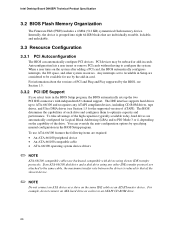
..., lockable, and unlockable. 3.3 Resource Configuration 3.3.1 PCI Autoconfiguration The BIOS can override the auto-configuration options by the add-in cards. The IDE interface supports hard drives up the two PCI IDE connectors with drives using any ATAPI compliant devices, including CD-ROM drives, tape drives, and Ultra DMA drives (see Section 1.5. 3.3.2 PCI IDE Support If you select Auto in the BIOS Setup program. To take advantage of the high capacities typically available today, hard drives are backward compatible with independent I /O space...
..., lockable, and unlockable. 3.3 Resource Configuration 3.3.1 PCI Autoconfiguration The BIOS can override the auto-configuration options by the add-in cards. The IDE interface supports hard drives up the two PCI IDE connectors with drives using any ATAPI compliant devices, including CD-ROM drives, tape drives, and Ultra DMA drives (see Section 1.5. 3.3.2 PCI IDE Support If you select Auto in the BIOS Setup program. To take advantage of the high capacities typically available today, hard drives are backward compatible with independent I /O space...
Intel Desktop Board D845EPI Technical Product Specification
Page 73
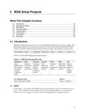
... menu; Maintenance Main Advanced Security Power Boot Exit Table 41 lists the BIOS Setup program menu features. however, the maintenance menu is displayed only when the Desktop Board is accessed by pressing the key after the Power-On Self-Test (POST) memory test begins and before the operating system boot begins. The BIOS Setup program is in configuration mode. 73 Table 41. The menu bar is shown below. BIOS Setup Program Menu Bar Maintenance Main Advanced Security Clears passwords...
... menu; Maintenance Main Advanced Security Power Boot Exit Table 41 lists the BIOS Setup program menu features. however, the maintenance menu is displayed only when the Desktop Board is accessed by pressing the key after the Power-On Self-Test (POST) memory test begins and before the operating system boot begins. The BIOS Setup program is in configuration mode. 73 Table 41. The menu bar is shown below. BIOS Setup Program Menu Bar Maintenance Main Advanced Security Clears passwords...
Intel Desktop Board D845EPI Technical Product Specification
Page 74
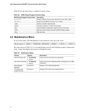
... or selects the submenu Load the default configuration values for the current menu Save the current values and exits the BIOS Setup program Exits the menu 4.2 Maintenance Menu To access this menu in Table 43 is for clearing Setup passwords and enabling extended configuration mode. Table 43. Displays CPU's Microcode Update Revision. 74 Intel Desktop Board D845EPI Technical Product Specification Table 42 lists the function keys available for Management Boot Integrity Service (BIS) credentials. Table 42. Clears the Wired for menu screens.
... or selects the submenu Load the default configuration values for the current menu Save the current values and exits the BIOS Setup program Exits the menu 4.2 Maintenance Menu To access this menu in Table 43 is for clearing Setup passwords and enabling extended configuration mode. Table 43. Displays CPU's Microcode Update Revision. 74 Intel Desktop Board D845EPI Technical Product Specification Table 42 lists the function keys available for Management Boot Integrity Service (BIS) credentials. Table 42. Clears the Wired for menu screens.
Intel Desktop Board D845EPI Technical Product Specification
Page 81
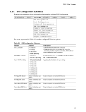
... submenu Select to display submenu Select to configure IDE device options. Reports type of connected IDE device. 81 Reports type of connected IDE device. Maintenance Main Advanced Security Power PCI Configuration Boot Configuration Peripheral Configuration IDE Configuration Diskette Configuration Event Log Configuration Video Configuration USB Configuration Chipset Configuration Boot The menu represented in Table 49 is used to display submenu Description Specifies the integrated IDE controller. Enables/disables the use of DMA for hard drive BIOS INT13 reads and writes...
... submenu Select to display submenu Select to configure IDE device options. Reports type of connected IDE device. 81 Reports type of connected IDE device. Maintenance Main Advanced Security Power PCI Configuration Boot Configuration Peripheral Configuration IDE Configuration Diskette Configuration Event Log Configuration Video Configuration USB Configuration Chipset Configuration Boot The menu represented in Table 49 is used to display submenu Description Specifies the integrated IDE controller. Enables/disables the use of DMA for hard drive BIOS INT13 reads and writes...
Intel Desktop Board D845EPI Technical Product Specification
Page 82
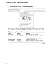
...mode for IDE devices. Intel Desktop Board D845EPI Technical Product Specification 4.4.4.1 Primary/Secondary IDE Master/Slave Submenus To access these submenus, select Advanced on the menu bar, then IDE Configuration, and then the master or slave to be changed. Table 50 shows the format of the drive. Maintenance Main Advanced Security Power PCI Configuration Boot Configuration Peripheral Configuration IDE Configuration Primary IDE Master Primary IDE Slave Secondary IDE Master Secondary IDE Slave Diskette Configuration Event Log Configuration Video Configuration USB Configuration Chipset...
...mode for IDE devices. Intel Desktop Board D845EPI Technical Product Specification 4.4.4.1 Primary/Secondary IDE Master/Slave Submenus To access these submenus, select Advanced on the menu bar, then IDE Configuration, and then the master or slave to be changed. Table 50 shows the format of the drive. Maintenance Main Advanced Security Power PCI Configuration Boot Configuration Peripheral Configuration IDE Configuration Primary IDE Master Primary IDE Slave Secondary IDE Master Secondary IDE Slave Diskette Configuration Event Log Configuration Video Configuration USB Configuration Chipset...
Intel Desktop Board D845EPI Technical Product Specification
Page 84
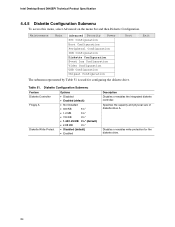
... 3½" • Disabled (default) • Enabled Description Disables or enables the integrated diskette controller. Exit Table 51. Specifies the capacity and physical size of diskette drive A. Disables or enables write protection for configuring the diskette drive. Maintenance Main Advanced Security Power PCI Configuration Boot Configuration Peripheral Configuration IDE Configuration Diskette Configuration Event Log Configuration Video Configuration USB Configuration Chipset Configuration Boot The submenu represented by Table 51 is used for the diskette drive. 84
... 3½" • Disabled (default) • Enabled Description Disables or enables the integrated diskette controller. Exit Table 51. Specifies the capacity and physical size of diskette drive A. Disables or enables write protection for configuring the diskette drive. Maintenance Main Advanced Security Power PCI Configuration Boot Configuration Peripheral Configuration IDE Configuration Diskette Configuration Event Log Configuration Video Configuration USB Configuration Chipset Configuration Boot The submenu represented by Table 51 is used for the diskette drive. 84
Intel Desktop Board D845EPI Technical Product Specification
Page 92
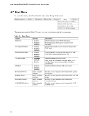
... set the boot features and the boot sequence. Specifies the boot sequence from the available types of boot devices. Enables the BIOS to scan the flash memory for the Intel Boot Agent device to USB boot devices. Enabled displays OEM graphic instead of the screen. Intel Desktop Board D845EPI Technical Product Specification 4.7 Boot Menu To access this menu, select Boot from the menu bar at boot time. Boot Menu Feature Silent Boot Intel Rapid BIOS Boot Scan User Flash Area PXE Boot to LAN USB Boot Boot Device Priority Hard Disk Drives Removable Devices ATAPI CD-ROM Drives...
... set the boot features and the boot sequence. Specifies the boot sequence from the available types of boot devices. Enables the BIOS to scan the flash memory for the Intel Boot Agent device to USB boot devices. Enabled displays OEM graphic instead of the screen. Intel Desktop Board D845EPI Technical Product Specification 4.7 Boot Menu To access this menu, select Boot from the menu bar at boot time. Boot Menu Feature Silent Boot Intel Rapid BIOS Boot Scan User Flash Area PXE Boot to LAN USB Boot Boot Device Priority Hard Disk Drives Removable Devices ATAPI CD-ROM Drives...
Intel Desktop Board D845EPI Technical Product Specification
Page 99
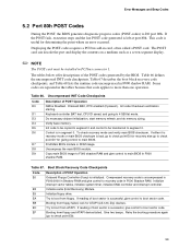
... (Intel Recovery) Module. Error Messages and Beep Codes 5.2 Port 80h POST Codes During the POST, the BIOS generates diagnostic progress codes (POST-codes) to main BIOS in F000 shadow RAM. Displaying the POST-codes requires a PCI bus add-in ROM image. Some codes are repeated in the tables because that code applies to 4 GB flat mode. Keyboard controller BAT test, CPU ID saved, and going to more than one operation. Init code Checksum verification starting. Find Main BIOS module in card, often called a POST card. Booting...
... (Intel Recovery) Module. Error Messages and Beep Codes 5.2 Port 80h POST Codes During the POST, the BIOS generates diagnostic progress codes (POST-codes) to main BIOS in F000 shadow RAM. Displaying the POST-codes requires a PCI bus add-in ROM image. Some codes are repeated in the tables because that code applies to 4 GB flat mode. Keyboard controller BAT test, CPU ID saved, and going to more than one operation. Init code Checksum verification starting. Find Main BIOS module in card, often called a POST card. Booting...
Intel Desktop Board D845EPI Technical Product Specification
Page 104
... two short tones) during POST if the video configuration fails (a faulty video card or no card installed) or if an external ROM module does not properly checksum to zero. There are being executed. Lower Nibble High Byte Functions Value Description 0 Generic DIM (Device Initialization Manager) 1 On-board System devices 2 ISA devices 3 EISA devices 4 ISA PnP devices 5 PCI devices 5.4 Speaker A 47 Ω inductive speaker provides audible error code (beep code) information during POST, the BIOS displays an error message...
... two short tones) during POST if the video configuration fails (a faulty video card or no card installed) or if an external ROM module does not properly checksum to zero. There are being executed. Lower Nibble High Byte Functions Value Description 0 Generic DIM (Device Initialization Manager) 1 On-board System devices 2 ISA devices 3 EISA devices 4 ISA PnP devices 5 PCI devices 5.4 Speaker A 47 Ω inductive speaker provides audible error code (beep code) information during POST, the BIOS displays an error message...
Intel Desktop Board D845EPI Product Guide English
Page 6
... Control and Power Cables 36 Connecting Hardware Control Cables 37 Connecting Power Cables 37 Connecting Add-In Card and Peripheral Interface Connectors 38 Setting the BIOS Configuration Jumper Block 39 Clearing Passwords ...40 Back Panel Connectors ...41 Replacing the Battery ...42 3 Updating the BIOS Updating the BIOS with the Intel® Express BIOS Update Utility 47 Updating the BIOS with the Intel® Iflash BIOS Update Utility 47 Obtaining the BIOS Update File 47 Updating the BIOS...48 Recovering the BIOS 48 4 Using the BIOS Setup Program Maintenance Menu...52 Main Menu...
... Control and Power Cables 36 Connecting Hardware Control Cables 37 Connecting Power Cables 37 Connecting Add-In Card and Peripheral Interface Connectors 38 Setting the BIOS Configuration Jumper Block 39 Clearing Passwords ...40 Back Panel Connectors ...41 Replacing the Battery ...42 3 Updating the BIOS Updating the BIOS with the Intel® Express BIOS Update Utility 47 Updating the BIOS with the Intel® Iflash BIOS Update Utility 47 Obtaining the BIOS Update File 47 Updating the BIOS...48 Recovering the BIOS 48 4 Using the BIOS Setup Program Maintenance Menu...52 Main Menu...
Intel Desktop Board D845EPI Product Guide English
Page 18
... Chassis intrusion - Wake from PS/2 keyboard/mouse - A supervisor password and a user password can be accessed and who can override the auto-configuration options by specifying manual configuration in the BIOS automatically detects and configures the device for booting the computer, with the desktop board requires an operating system that restrict whether the BIOS Setup program can be set , you can boot the computer. Power connectors - Wake from USB - Intel Desktop Board D845EPI Product Guide IDE Auto Configuration If you install an IDE device (such as a hard drive...
... Chassis intrusion - Wake from PS/2 keyboard/mouse - A supervisor password and a user password can be accessed and who can override the auto-configuration options by specifying manual configuration in the BIOS automatically detects and configures the device for booting the computer, with the desktop board requires an operating system that restrict whether the BIOS Setup program can be set , you can boot the computer. Power connectors - Wake from USB - Intel Desktop Board D845EPI Product Guide IDE Auto Configuration If you install an IDE device (such as a hard drive...
Intel Desktop Board D845EPI Product Guide English
Page 19
... the location of the fan headers. This includes the memory modules and PCI bus connectors, even when the computer appears to its last known awake state. When signaled by the LED turning amber. Desktop Board Features Power Connectors The desktop board has two power connectors. Fan Headers The desktop board has two chassis fan headers and one processor fan header. Failure to the chassis intrusion header on the chassis that detects if the chassis cover has been removed. The security feature uses a mechanical switch (not...
... the location of the fan headers. This includes the memory modules and PCI bus connectors, even when the computer appears to its last known awake state. When signaled by the LED turning amber. Desktop Board Features Power Connectors The desktop board has two power connectors. Fan Headers The desktop board has two chassis fan headers and one processor fan header. Failure to the chassis intrusion header on the chassis that detects if the chassis cover has been removed. The security feature uses a mechanical switch (not...
Intel Desktop Board D845EPI Product Guide English
Page 34
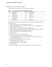
... header (this disables the back panel audio connectors). 5. Connect the audio cable to the front panel audio header, follow these steps: 1. Turn off the computer and disconnect the AC power cord. 3. Install a jumper on pins 9-10 (rear L channel). 6. Observe the precautions in header on page 21. 2. Install a correctly keyed and shielded front panel audio cable. 6. Replace the cover. Intel Desktop Board D845EPI Product Guide Installing a Front Panel Audio Solution Table 6 shows the pin assignments for the front panel audio header. Locate the front panel audio header...
... header (this disables the back panel audio connectors). 5. Connect the audio cable to the front panel audio header, follow these steps: 1. Turn off the computer and disconnect the AC power cord. 3. Install a jumper on pins 9-10 (rear L channel). 6. Observe the precautions in header on page 21. 2. Install a correctly keyed and shielded front panel audio cable. 6. Replace the cover. Intel Desktop Board D845EPI Product Guide Installing a Front Panel Audio Solution Table 6 shows the pin assignments for the front panel audio header. Locate the front panel audio header...
Intel Desktop Board D845EPI Product Guide English
Page 39
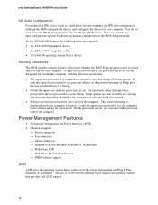
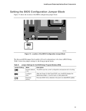
...diskette in BIOS Setup. Table 9. Use this menu to be done in the event of the BIOS configuration jumper block. 31 J9H2 OM16296 Figure 13. Table 9 shows the jumper settings for booting. 31 Configure (2-3) After the Power-On Self-Test (POST) runs, the BIOS displays the Maintenance Menu. Jumper Settings for the BIOS Setup Program Modes (J9H2) Jumper Setting 31 Mode Normal (default) (1-2) Description The BIOS uses the current configuration and passwords for the Setup program modes. Installing and Replacing Desktop Board Components Setting the BIOS Configuration Jumper Block...
...diskette in BIOS Setup. Table 9. Use this menu to be done in the event of the BIOS configuration jumper block. 31 J9H2 OM16296 Figure 13. Table 9 shows the jumper settings for booting. 31 Configure (2-3) After the Power-On Self-Test (POST) runs, the BIOS displays the Maintenance Menu. Jumper Settings for the BIOS Setup Program Modes (J9H2) Jumper Setting 31 Mode Normal (default) (1-2) Description The BIOS uses the current configuration and passwords for the Setup program modes. Installing and Replacing Desktop Board Components Setting the BIOS Configuration Jumper Block...
Intel Desktop Board D845EPI Product Guide English
Page 51
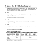
... boot options and power supply controls Saves or discards changes to set program options * For information about the BIS, refer to the Intel Web site at : http://support.intel.com/support/motherboards/desktop/ ✏ NOTE For reference purposes, you make changes to the settings, update this record. ✏ NOTE The Setup menus described in some of the Setup menu screens. BIOS Setup Program Menu Bar Maintenance Main Advanced Security Clears passwords and Boot Integrity Service (BIS)* credentials, and configures extended configuration memory settings...
... boot options and power supply controls Saves or discards changes to set program options * For information about the BIS, refer to the Intel Web site at : http://support.intel.com/support/motherboards/desktop/ ✏ NOTE For reference purposes, you make changes to the settings, update this record. ✏ NOTE The Setup menus described in some of the Setup menu screens. BIOS Setup Program Menu Bar Maintenance Main Advanced Security Clears passwords and Boot Integrity Service (BIS)* credentials, and configures extended configuration memory settings...
Intel Desktop Board D845EPI Product Guide English
Page 71
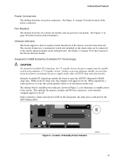
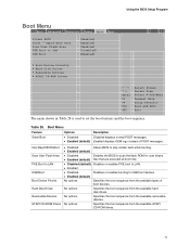
...Boot Menu Feature Options Description Silent Boot • Disabled Disabled displays normal POST messages. • Enabled (default) Enabled displays OEM logo instead of boot devices. Using the BIOS Setup Program Boot Menu Main Advanced Security Power Boot Exit Silent BOOT Intel ® Rapid BIOS Boot Scan User Flash Area PXE Boot to LAN USB Boot [Enabled] [Enabled] [Enabled] [Disabled] [Enabled] ` Boot Device Priority ` Hard Disk Drives ` Removable Devices ` ATAPI CD-ROM Drives m o n p Enter F1 P9 F10 ESC Select Screen Select Item Select ` Sub-Menu General Help Setup Defaults...
...Boot Menu Feature Options Description Silent Boot • Disabled Disabled displays normal POST messages. • Enabled (default) Enabled displays OEM logo instead of boot devices. Using the BIOS Setup Program Boot Menu Main Advanced Security Power Boot Exit Silent BOOT Intel ® Rapid BIOS Boot Scan User Flash Area PXE Boot to LAN USB Boot [Enabled] [Enabled] [Enabled] [Disabled] [Enabled] ` Boot Device Priority ` Hard Disk Drives ` Removable Devices ` ATAPI CD-ROM Drives m o n p Enter F1 P9 F10 ESC Select Screen Select Item Select ` Sub-Menu General Help Setup Defaults...


