
Product Guide
Page 4
... and Removing the AGP Card 27 Installing an AGP Card 27 Removing the AGP Card 28 Connecting the IDE Cable 28 Setting the BIOS Configuration Jumper Block 30 Installing the Front Panel Audio Solution 31 Clearing Passwords...32 Replacing the Battery ...33 3 Updating the BIOS Updating the BIOS with the Intel® Express BIOS Update Utility 37 Updating the BIOS with the Intel® Flash Memory Update Utility 38 Obtaining the BIOS Update File 38 Updating the BIOS...38 Recovering the BIOS 39 4 Using the BIOS Setup Program Maintenance Menu...42 Extended Configuration Submenu 43 Main Menu...
... and Removing the AGP Card 27 Installing an AGP Card 27 Removing the AGP Card 28 Connecting the IDE Cable 28 Setting the BIOS Configuration Jumper Block 30 Installing the Front Panel Audio Solution 31 Clearing Passwords...32 Replacing the Battery ...33 3 Updating the BIOS Updating the BIOS with the Intel® Express BIOS Update Utility 37 Updating the BIOS with the Intel® Flash Memory Update Utility 38 Obtaining the BIOS Update File 38 Updating the BIOS...38 Recovering the BIOS 39 4 Using the BIOS Setup Program Maintenance Menu...42 Extended Configuration Submenu 43 Main Menu...
Product Guide
Page 6
.... Jumper Settings for the BIOS Setup Program Modes (J8H2 30 5. System Memory Map 68 32. Peripheral Configuration Submenu 48 14. Video Configuration Submenu 54 19. Boot Menu ...57 24. Exit Menu...60 29. Front Panel Audio Header Signal Names (J8B1 63 30. Front Panel USB 2.0 Header (J9F1 67 31. Processors Supported by the Desktop Boards D845EPT2 and D845EBG2 11 3. RJ-45 LAN Connector LEDs 14 4. Power Menu ...56 22. Beep Codes...71 35. EMC Regulations...75 vi Floppy Configuration Submenu 52 17. Removable Devices...
.... Jumper Settings for the BIOS Setup Program Modes (J8H2 30 5. System Memory Map 68 32. Peripheral Configuration Submenu 48 14. Video Configuration Submenu 54 19. Boot Menu ...57 24. Exit Menu...60 29. Front Panel Audio Header Signal Names (J8B1 63 30. Front Panel USB 2.0 Header (J9F1 67 31. Processors Supported by the Desktop Boards D845EPT2 and D845EBG2 11 3. RJ-45 LAN Connector LEDs 14 4. Power Menu ...56 22. Beep Codes...71 35. EMC Regulations...75 vi Floppy Configuration Submenu 52 17. Removable Devices...
Product Guide
Page 7
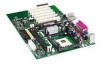
....0 inches (Desktop Board D845EBG2) Support for a single Intel® Pentium® 4 processor with SPX† software support Intel® 82562ET 10/100 Mbit/sec Platform LAN Connect (PLC) device and RJ-45 connector • Up to the back panel - 1 Desktop Board Features ✏ NOTE The Intel® Desktop Board D845EPT2 layout was used for up to six Hi-Speed Universal Serial Bus 2.0 (USB 2.0) ports • 4 Mbit Firmware Hub (FWH) SMSC LPC47M102S low pin count (LPC) interface I /O Control Graphics Audio LAN (optional) Peripheral Interfaces...
....0 inches (Desktop Board D845EBG2) Support for a single Intel® Pentium® 4 processor with SPX† software support Intel® 82562ET 10/100 Mbit/sec Platform LAN Connect (PLC) device and RJ-45 connector • Up to the back panel - 1 Desktop Board Features ✏ NOTE The Intel® Desktop Board D845EPT2 layout was used for up to six Hi-Speed Universal Serial Bus 2.0 (USB 2.0) ports • 4 Mbit Firmware Hub (FWH) SMSC LPC47M102S low pin count (LPC) interface I /O Control Graphics Audio LAN (optional) Peripheral Interfaces...

Product Guide
Page 9
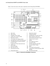
... S BIOS configuration jumper block E Back panel connectors T SCSI hard drive activity LED connector F 12 V processor core voltage connector U Chassis intrusion connector G Rear chassis fan connector (tachometer input) V Speaker H Intel 82845E Memory Controller Hub (MCH) W Front chassis fan connector I Processor socket X Front panel header J Processor fan connector (tachometer input) Y Alternate power/sleep LED header K DIMM sockets Z Front panel USB 2.0 header L Serial port B header AA Battery M Main power connector BB PCI bus add-in card connectors N Secondary IDE connector...
... S BIOS configuration jumper block E Back panel connectors T SCSI hard drive activity LED connector F 12 V processor core voltage connector U Chassis intrusion connector G Rear chassis fan connector (tachometer input) V Speaker H Intel 82845E Memory Controller Hub (MCH) W Front chassis fan connector I Processor socket X Front panel header J Processor fan connector (tachometer input) Y Alternate power/sleep LED header K DIMM sockets Z Front panel USB 2.0 header L Serial port B header AA Battery M Main power connector BB PCI bus add-in card connectors N Secondary IDE connector...
Product Guide
Page 10
... BIOS configuration jumper block E Back panel connectors T SCSI hard drive activity LED connector F 12 V processor core voltage connector U Chassis intrusion connector G Rear chassis fan connector (tachometer input) V Speaker H Intel 82845E Memory Controller Hub (MCH) W Front chassis fan connector I Processor socket X Front panel header J Processor fan connector (tachometer input) Y Alternate power/sleep LED header K DIMM sockets Z Front panel USB 2.0 header L Serial port B header AA Battery M Main power connector BB PCI bus add-in card connectors N Secondary IDE connector CC...
... BIOS configuration jumper block E Back panel connectors T SCSI hard drive activity LED connector F 12 V processor core voltage connector U Chassis intrusion connector G Rear chassis fan connector (tachometer input) V Speaker H Intel 82845E Memory Controller Hub (MCH) W Front chassis fan connector I Processor socket X Front panel header J Processor fan connector (tachometer input) Y Alternate power/sleep LED header K DIMM sockets Z Front panel USB 2.0 header L Serial port B header AA Battery M Main power connector BB PCI bus add-in card connectors N Secondary IDE connector CC...

Product Guide
Page 11
... higher speed processors. The Desktop Boards D845EPT2 and D845EBG2 require an ATX12V compliant power supply to function according to the Intel 845E chipset and Intel Pentium 4 processor. Processors are needed to provide extra power to Intel desktop board specifications. Both Desktop Boards D845EPT2 and D845EBG2 have two ATX12V compliant power supply connectors that are not included with the Intel desktop boards and must be removed and replaced to the Intel customer support World Wide Web site: http://support.intel.com/support/motherboards/desktop/ For instructions on installing...
... higher speed processors. The Desktop Boards D845EPT2 and D845EBG2 require an ATX12V compliant power supply to function according to the Intel 845E chipset and Intel Pentium 4 processor. Processors are needed to provide extra power to Intel desktop board specifications. Both Desktop Boards D845EPT2 and D845EBG2 have two ATX12V compliant power supply connectors that are not included with the Intel desktop boards and must be removed and replaced to the Intel customer support World Wide Web site: http://support.intel.com/support/motherboards/desktop/ For instructions on installing...
Product Guide
Page 17
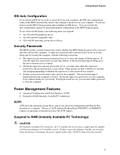
... the user restricted access to Setup. • If both passwords are then available for your computer. If only the supervisor password is set , you install an IDE device (such as a hard drive) in your computer, the IDE auto-configuration utility in the BIOS Setup program. Desktop Board Features IDE Auto Configuration If you can enter either the supervisor password or the user password to RAM (Instantly Available PC technology) ACPI ACPI gives the operating system direct control over the power management and Plug...
... the user restricted access to Setup. • If both passwords are then available for your computer. If only the supervisor password is set , you install an IDE device (such as a hard drive) in your computer, the IDE auto-configuration utility in the BIOS Setup program. Desktop Board Features IDE Auto Configuration If you can enter either the supervisor password or the user password to RAM (Instantly Available PC technology) ACPI ACPI gives the operating system direct control over the power management and Plug...

Product Guide
Page 18
... LED turning amber. For more information on the front panel, the sleep state is standby power to be off . This includes the memory modules and PCI bus connectors, even when the computer appears to the system. Intel Desktop Boards D845EPT2 and D845EBG2 Product Guide Instantly Available PC technology enables the board to enter the ACPI S3 (Suspend-to support the standard Instantly Available (ACPI S3 sleep state) configuration. If the system has a dual-colored power LED...
... LED turning amber. For more information on the front panel, the sleep state is standby power to be off . This includes the memory modules and PCI bus connectors, even when the computer appears to the system. Intel Desktop Boards D845EPT2 and D845EBG2 Product Guide Instantly Available PC technology enables the board to enter the ACPI S3 (Suspend-to support the standard Instantly Available (ACPI S3 sleep state) configuration. If the system has a dual-colored power LED...

Product Guide
Page 27
... reconnect the AC power cord. Turn off all peripheral devices connected to installing the DIMMs. 11. Installing an AGP Card Follow these steps: 1. Installing and Replacing Desktop Board Components 5. Holding the DIMM by the edges, lift it away from the computer. 4. Position the DIMM above the socket. Insert the bottom edge of the DIMM socket(s) are firmly in the AGP connector. 2. Gently spread the...
... reconnect the AC power cord. Turn off all peripheral devices connected to installing the DIMMs. 11. Installing an AGP Card Follow these steps: 1. Installing and Replacing Desktop Board Components 5. Holding the DIMM by the edges, lift it away from the computer. 4. Position the DIMM above the socket. Insert the bottom edge of the DIMM socket(s) are firmly in the AGP connector. 2. Gently spread the...

Product Guide
Page 30
...Test (POST) runs, the BIOS displays the Maintenance Menu. Use this menu to be done in unreliable computer operation. The location of the board's BIOS configuration jumper is shown in the event of the BIOS Configuration Jumper Block The three-pin BIOS jumper block enables all Intel desktop board configurations to clear passwords. 31 Recovery (None) The BIOS recovers data from the computer before changing the jumper. Location of a failed BIOS update. 30 Intel Desktop Boards D845EPT2 and D845EBG2 Product Guide Setting the BIOS Configuration Jumper Block CAUTION Always turn off...
...Test (POST) runs, the BIOS displays the Maintenance Menu. Use this menu to be done in unreliable computer operation. The location of the board's BIOS configuration jumper is shown in the event of the BIOS Configuration Jumper Block The three-pin BIOS jumper block enables all Intel desktop board configurations to clear passwords. 31 Recovery (None) The BIOS recovers data from the computer before changing the jumper. Location of a failed BIOS update. 30 Intel Desktop Boards D845EPT2 and D845EBG2 Product Guide Setting the BIOS Configuration Jumper Block CAUTION Always turn off...

Product Guide
Page 31
.... 4. To restore back panel operations, follow these steps: 1. Turn off all peripheral devices connected to the computer. Connect the audio cable to the front panel audio header, follow these steps: 1. Installing and Replacing Desktop Board Components Installing the Front Panel Audio Solution To install the cable that connects the front panel audio solution to the front panel audio solution. 8. Remove the two jumpers from the header to disable the back panel audio connectors. 6. Install a correctly keyed and shielded front panel audio cable. 7. Observe the precautions...
.... 4. To restore back panel operations, follow these steps: 1. Turn off all peripheral devices connected to the computer. Connect the audio cable to the front panel audio header, follow these steps: 1. Installing and Replacing Desktop Board Components Installing the Front Panel Audio Solution To install the cable that connects the front panel audio solution to the front panel audio solution. 8. Remove the two jumpers from the header to disable the back panel audio connectors. 6. Install a correctly keyed and shielded front panel audio cable. 7. Observe the precautions...

Product Guide
Page 32
... . Replace the cover, plug in the computer, turn on pins 2-3 as shown below . 31 6. Setup displays the maintenance menu again. 9. Intel Desktop Boards D845EPT2 and D845EBG2 Product Guide Clearing Passwords This procedure assumes that you confirm clearing the password. Observe the precautions in the computer, and turn on page 21. 2. Use the arrow keys to normal mode. 1. Replace the cover, plug in "Before You Begin" on the computer, and allow it to boot...
... . Replace the cover, plug in the computer, turn on pins 2-3 as shown below . 31 6. Setup displays the maintenance menu again. 9. Intel Desktop Boards D845EPT2 and D845EBG2 Product Guide Clearing Passwords This procedure assumes that you confirm clearing the password. Observe the precautions in the computer, and turn on page 21. 2. Use the arrow keys to normal mode. 1. Replace the cover, plug in "Before You Begin" on the computer, and allow it to boot...

Product Guide
Page 41
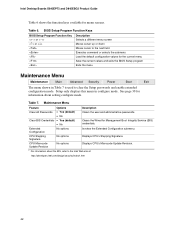
... Power Configures power management features Boot Selects boot options and power supply controls Exit Saves or discards changes to set program options * For information about the BIS, refer to the Intel Desktop Board D845EPT2/D845EBG2 Technical Product Specification or the Intel customer support World Wide Web site: http://support.intel.com/support/motherboards/desktop ✏ NOTE For reference purposes, you make changes to the settings, update this record. ✏ NOTE The Setup menus described in some of the Setup menu screens...
... Power Configures power management features Boot Selects boot options and power supply controls Exit Saves or discards changes to set program options * For information about the BIS, refer to the Intel Desktop Board D845EPT2/D845EBG2 Technical Product Specification or the Intel customer support World Wide Web site: http://support.intel.com/support/motherboards/desktop ✏ NOTE For reference purposes, you make changes to the settings, update this record. ✏ NOTE The Setup menus described in some of the Setup menu screens...
Product Guide
Page 42
... configure mode. Invokes the Extended Configuration submenu. Table 7. BIOS Setup Program Function Keys BIOS Setup Program Function Key or or Description Selects a different menu screen Moves cursor up or down Moves cursor to the Intel Web site at: http://developer.intel.com/design/security/index1.htm 42 Clears the Wired for menu screens. Intel Desktop Boards D845EPT2 and D845EBG2 Product Guide Table 6 shows the function keys available for Management Boot Integrity Service (BIS) credentials. Table 6. Displays CPU...
... configure mode. Invokes the Extended Configuration submenu. Table 7. BIOS Setup Program Function Keys BIOS Setup Program Function Key or or Description Selects a different menu screen Moves cursor up or down Moves cursor to the Intel Web site at: http://developer.intel.com/design/security/index1.htm 42 Clears the Wired for menu screens. Intel Desktop Boards D845EPT2 and D845EBG2 Product Guide Table 6 shows the function keys available for Management Boot Integrity Service (BIS) credentials. Table 6. Displays CPU...

Product Guide
Page 43
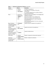
... Advanced Menu as: "Extended Menu: Used." To Pre. Cache lookups are not performed. Well suited for applications not supporting Write Combining. Options • Default (default) • User-Defined • USWC • UC (default) • Auto (default) • User Defined • 3 • 2 • Auto (default) • 3 • 2 • Auto (default) • 3 • 2 • Auto (default) • 7 • 6 • 5 • Auto (default) Description User Defined allows setting memory control and video memory cache mode. Selects the number of clock cycles...
... Advanced Menu as: "Extended Menu: Used." To Pre. Cache lookups are not performed. Well suited for applications not supporting Write Combining. Options • Default (default) • User-Defined • USWC • UC (default) • Auto (default) • User Defined • 3 • 2 • Auto (default) • 3 • 2 • Auto (default) • 3 • 2 • Auto (default) • 7 • 6 • 5 • Auto (default) Description User Defined allows setting memory control and video memory cache mode. Selects the number of clock cycles...
Product Guide
Page 49
... the interrupt IRQ7. ECP is Extended Parallel Port mode, a high-speed bi-directional mode. Peripheral Configuration Submenu (continued) Feature Parallel Port Mode Base I /O address for the parallel port. Enables or disables the onboard audio subsystem. An * (asterisk) displayed next to ECP) Audio Device LAN Device (This feature is present only when there is disabled. Not available if the parallel port is onboard LAN) Options • Disabled • Enabled • Auto (default) • Output Only • Bi-directional...
... the interrupt IRQ7. ECP is Extended Parallel Port mode, a high-speed bi-directional mode. Peripheral Configuration Submenu (continued) Feature Parallel Port Mode Base I /O address for the parallel port. Enables or disables the onboard audio subsystem. An * (asterisk) displayed next to ECP) Audio Device LAN Device (This feature is present only when there is disabled. Not available if the parallel port is onboard LAN) Options • Disabled • Enabled • Auto (default) • Output Only • Bi-directional...

Product Guide
Page 50
... Primary IDE Slave No options Reports type of connected IDE device. Primary enables only the primary IDE controller. When selected, displays the Primary IDE Slave submenu. When selected, displays the Secondary IDE Master submenu. Intel Desktop Boards D845EPT2 and D845EBG2 Product Guide IDE Configuration Submenu Maintenance Main Advanced Security Power Boot Exit PCI Configuration Boot Configuration Peripheral Configuration IDE Configuration Floppy Configuration Event Log Configuration Video Configuration USB Configuration This submenu shown in Table 14 is used to initiate...
... Primary IDE Slave No options Reports type of connected IDE device. Primary enables only the primary IDE controller. When selected, displays the Primary IDE Slave submenu. When selected, displays the Secondary IDE Master submenu. Intel Desktop Boards D845EPT2 and D845EBG2 Product Guide IDE Configuration Submenu Maintenance Main Advanced Security Power Boot Exit PCI Configuration Boot Configuration Peripheral Configuration IDE Configuration Floppy Configuration Event Log Configuration Video Configuration USB Configuration This submenu shown in Table 14 is used to initiate...

Product Guide
Page 51
... PIO Mode (Note) Options None • None • User • Auto (default) • CD-ROM • ATAPI Removable • Other ATAPI • IDE Removable None • Auto (default) • Disabled • Auto (default) • 0 • 1 • 2 • 3 • 4 Description Displays the type of these IDE submenus. Using the Setup Program Primary/Secondary IDE Master/Slave Submenus Maintenance Main Advanced Security Boot Configuration Peripheral Configuration IDE Configuration Floppy Configuration Event Log Configuration Video Configuration USB Configuration Power...
... PIO Mode (Note) Options None • None • User • Auto (default) • CD-ROM • ATAPI Removable • Other ATAPI • IDE Removable None • Auto (default) • Disabled • Auto (default) • 0 • 1 • 2 • 3 • 4 Description Displays the type of these IDE submenus. Using the Setup Program Primary/Secondary IDE Master/Slave Submenus Maintenance Main Advanced Security Boot Configuration Peripheral Configuration IDE Configuration Floppy Configuration Event Log Configuration Video Configuration USB Configuration Power...

Product Guide
Page 52
...ARMD device emulation type by BIOS. Table 16. Intel Desktop Boards D845EPT2 and D845EBG2 Product Guide Table 15. Floppy Configuration Submenu Maintenance Main Advanced Security Power Boot Exit PCI Configuration Boot Configuration Peripheral Configuration IDE Configuration Floppy Configuration Event Log Configuration Video Configuration USB Configuration This submenu shown in Table 16 is installed. Disables or enables write-protect for the floppy drive. 52 Note: These configuration options appear only if an IDE device is used to configure the floppy drive. Primary...
...ARMD device emulation type by BIOS. Table 16. Intel Desktop Boards D845EPT2 and D845EBG2 Product Guide Table 15. Floppy Configuration Submenu Maintenance Main Advanced Security Power Boot Exit PCI Configuration Boot Configuration Peripheral Configuration IDE Configuration Floppy Configuration Event Log Configuration Video Configuration USB Configuration This submenu shown in Table 16 is installed. Disables or enables write-protect for the floppy drive. 52 Note: These configuration options appear only if an IDE device is used to configure the floppy drive. Primary...
Product Guide
Page 55
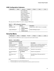
... password set . USB Configuration Submenu Feature Options High Speed USB Legacy USB Support • Disabled • Enabled (default) • Disabled • Enabled (default) Description Disables when a USB 2.0 driver is not available. Specifies the user password. Sets BIOS Setup Utility access rights for user level. Table 20. Security Menu If no password entered previously: Feature Options Description Supervisor Password Is User Password Is Set Supervisor Password Set User Password Clear User Password (Note 1) User Access Level (Note 2) No options No options...
... password set . USB Configuration Submenu Feature Options High Speed USB Legacy USB Support • Disabled • Enabled (default) • Disabled • Enabled (default) Description Disables when a USB 2.0 driver is not available. Specifies the user password. Sets BIOS Setup Utility access rights for user level. Table 20. Security Menu If no password entered previously: Feature Options Description Supervisor Password Is User Password Is Set Supervisor Password Set User Password Clear User Password (Note 1) User Access Level (Note 2) No options No options...


