
Product Guide
Page 5
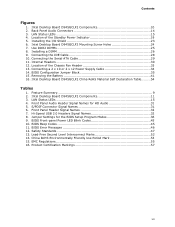
Contents 1 Desktop Board Features Desktop Board Components 10 Processor ...12 Main Memory...12 Intel® 945GC Express Chipset 13 S-Video Support 13 Onboard Audio Subsystem 13 Input/Output (I/O) Controller 14 LAN Subsystem 15 LAN Subsystem Software 15...Begin 21 Installation Precautions 22 Prevent Power Supply Overload 22 Observe Safety and Regulatory Requirements 22 Installing the I/O Shield 23 Installing and Removing the Desktop Board 24 Installing and Removing Memory 25 Installing DIMMs 25 Removing DIMMs 27 Connecting the IDE Cable 27 Connecting the Serial ATA (SATA) Cable ...
Contents 1 Desktop Board Features Desktop Board Components 10 Processor ...12 Main Memory...12 Intel® 945GC Express Chipset 13 S-Video Support 13 Onboard Audio Subsystem 13 Input/Output (I/O) Controller 14 LAN Subsystem 15 LAN Subsystem Software 15...Begin 21 Installation Precautions 22 Prevent Power Supply Overload 22 Observe Safety and Regulatory Requirements 22 Installing the I/O Shield 23 Installing and Removing the Desktop Board 24 Installing and Removing Memory 25 Installing DIMMs 25 Removing DIMMs 27 Connecting the IDE Cable 27 Connecting the Serial ATA (SATA) Cable ...
Product Guide
Page 7
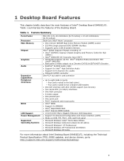
...Status LEDs 15 4. S/PDIF Connector Signal Names 31 6. BIOS Front-panel Power LED Blink Codes 45 10. Intel Desktop Board D945GCLF2 Mounting Screw Holes 24 7. Installing a DIMM 26 9. Location of the Standby Power Indicator 19 5. Front Panel Header Signal ...Names 32 7. Intel Desktop Board D945GCLF2 Components 10 2. LAN Status LEDs 15 4. Connecting the IDE Cable 28 10. Connecting a 2 x 10 or 2 x 12 Power Supply Cable 34 14. BIOS Configuration Jumper Block 35 15. Removing the...
...Status LEDs 15 4. S/PDIF Connector Signal Names 31 6. BIOS Front-panel Power LED Blink Codes 45 10. Intel Desktop Board D945GCLF2 Mounting Screw Holes 24 7. Installing a DIMM 26 9. Location of the Standby Power Indicator 19 5. Front Panel Header Signal ...Names 32 7. Intel Desktop Board D945GCLF2 Components 10 2. LAN Status LEDs 15 4. Connecting the IDE Cable 28 10. Connecting a 2 x 10 or 2 x 12 Power Supply Cable 34 14. BIOS Configuration Jumper Block 35 15. Removing the...
Product Guide
Page 9
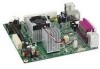
....45 millimeters [6.75 inches]) Dual-Core Intel® Atom™ processor • One 240-pin SDRAM Dual Inline Memory Module (DIMM) socket • 533 MHz single channel DDR2 SDRAM interface • Supports up to 2 GB of system memory Intel® 945GC Express Chipset consisting of Intel® Desktop Board D945GCLF2. 1 Desktop Board Features This chapter briefly describes the main...
....45 millimeters [6.75 inches]) Dual-Core Intel® Atom™ processor • One 240-pin SDRAM Dual Inline Memory Module (DIMM) socket • 533 MHz single channel DDR2 SDRAM interface • Supports up to 2 GB of system memory Intel® 945GC Express Chipset consisting of Intel® Desktop Board D945GCLF2. 1 Desktop Board Features This chapter briefly describes the main...

Product Guide
Page 10
Intel Desktop Board D945GCLF2 Components 10 Figure 1. Intel Desktop Board D945GCLF2 Product Guide Desktop Board Components Figure 1 shows the location of the major components on Intel Desktop Board D945GCLF2.
Intel Desktop Board D945GCLF2 Components 10 Figure 1. Intel Desktop Board D945GCLF2 Product Guide Desktop Board Components Figure 1 shows the location of the major components on Intel Desktop Board D945GCLF2.

Product Guide
Page 15
...rate is operating. These LEDs indicate the operating states of the LAN. Figure 3. Desktop Board Features LAN Subsystem The LAN, based on the RealTek RTL8111C Ethernet Controller, provides the following functions: • 10/100/1000 Mb/s Gigabit Ethernet LAN • Support for RJ-45 connector with ... Subsystem Software For LAN software and drivers, refer to the Intel Desktop D945GCLF2 link on the back panel (see Figure 3). LAN Status LEDs Two LEDs are built into the RJ-45 LAN connector located on Intel's World Wide Web site at http://support.intel.com/support/motherboards/desktop.
...rate is operating. These LEDs indicate the operating states of the LAN. Figure 3. Desktop Board Features LAN Subsystem The LAN, based on the RealTek RTL8111C Ethernet Controller, provides the following functions: • 10/100/1000 Mb/s Gigabit Ethernet LAN • Support for RJ-45 connector with ... Subsystem Software For LAN software and drivers, refer to the Intel Desktop D945GCLF2 link on the back panel (see Figure 3). LAN Status LEDs Two LEDs are built into the RJ-45 LAN connector located on Intel's World Wide Web site at http://support.intel.com/support/motherboards/desktop.

Product Guide
Page 29
Observe the precautions in "Before You Begin" on the board (Figure 10, A). 3. Connecting the Serial ATA Cable 29 Attach the cable end without the lock to the connector on page 21. 2. For correct cable function: 1. Attach the locking cable end to the drive (Figure 10, B). Figure 10. Installing and Replacing Desktop Board Components Connecting the Serial ATA (SATA) Cable The SATA cable supports the Serial ATA protocol and connects a single drive to the desktop board.
Observe the precautions in "Before You Begin" on the board (Figure 10, A). 3. Connecting the Serial ATA Cable 29 Attach the cable end without the lock to the connector on page 21. 2. For correct cable function: 1. Attach the locking cable end to the drive (Figure 10, B). Figure 10. Installing and Replacing Desktop Board Components Connecting the Serial ATA (SATA) Cable The SATA cable supports the Serial ATA protocol and connects a single drive to the desktop board.

Product Guide
Page 31
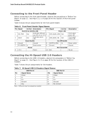
...audio header. Turn off all peripheral devices connected to the front panel audio header, follow these steps: 1. Installing and Replacing Desktop Board Components Connecting the Front Panel Audio Header Figure 11, A shows the location of the front panel header. Turn off the ...1 PORT 1L 3 PORT 1R 5 PORT 2R 7 SENSE_SEND 9 PORT 2L Pin Signal Name 2 GND 4 PRESENCE# 6 SENSE1_RETURN 8 KEY (no pin) 10 SENSE2_RETURN To install a cable that connects a front panel audio solution to the computer. Table 5. Observe the precautions in "Before You Begin" on page 21...
...audio header. Turn off all peripheral devices connected to the front panel audio header, follow these steps: 1. Installing and Replacing Desktop Board Components Connecting the Front Panel Audio Header Figure 11, A shows the location of the front panel header. Turn off the ...1 PORT 1L 3 PORT 1R 5 PORT 2R 7 SENSE_SEND 9 PORT 2L Pin Signal Name 2 GND 4 PRESENCE# 6 SENSE1_RETURN 8 KEY (no pin) 10 SENSE2_RETURN To install a cable that connects a front panel audio solution to the computer. Table 5. Observe the precautions in "Before You Begin" on page 21...
Product Guide
Page 32
.../Off Switch 5 Ground 7 FP_RESET# In Ground Reset switch 6 SWITCH_ON# In 8 Ground Power switch Ground Power Not Connected 9 +5 V Power 10 N/C No pin Connecting the Hi-Speed USB 2.0 Headers Before connecting to the front panel header, observe the precautions in "Before You Begin" on... for the front panel header. Table 7. Table 6 shows the pin assignments for the headers. See Figure 11, D on page 21. Intel Desktop Board D945GCLF2 Product Guide Connecting to the Front Panel Header Before connecting to the USB 2.0 headers, observe the precautions in "Before You Begin" on...
.../Off Switch 5 Ground 7 FP_RESET# In Ground Reset switch 6 SWITCH_ON# In 8 Ground Power switch Ground Power Not Connected 9 +5 V Power 10 N/C No pin Connecting the Hi-Speed USB 2.0 Headers Before connecting to the front panel header, observe the precautions in "Before You Begin" on... for the front panel header. Table 7. Table 6 shows the pin assignments for the headers. See Figure 11, D on page 21. Intel Desktop Board D945GCLF2 Product Guide Connecting to the Front Panel Header Before connecting to the USB 2.0 headers, observe the precautions in "Before You Begin" on...

Product Guide
Page 34
... a 2 x 10 or 2 x 12 Power Supply Cable 1. Intel Desktop Board D945GCLF2 Product Guide Connecting Power Supply Cables CAUTION Failure to use an appropriate power supply and/or not connecting the 12 V (2 x 2) power connector to the Desktop Board may not function properly. Observe the precautions in damage to the 2 x 12 connector (Figure 13). 34 Connect the 12 V processor core...
... a 2 x 10 or 2 x 12 Power Supply Cable 1. Intel Desktop Board D945GCLF2 Product Guide Connecting Power Supply Cables CAUTION Failure to use an appropriate power supply and/or not connecting the 12 V (2 x 2) power connector to the Desktop Board may not function properly. Observe the precautions in damage to the 2 x 12 connector (Figure 13). 34 Connect the 12 V processor core...

Product Guide
Page 36
... power adapter). 3. Press and Setup displays a pop-up screen requesting that the board is set to boot. 7. Turn off the computer. Use this menu to save the current values and exit Setup. 10. Press to clear passwords. Observe the precautions in the computer, turn on pins ... computer starts the Setup program. Turn off all peripheral devices connected to select Clear Passwords. Remove the computer cover. 4. Intel Desktop Board D945GCLF2 Product Guide Figure 14 shows the location of a failed BIOS update. Find the configuration jumper block (see Figure 14, B). 5.
... power adapter). 3. Press and Setup displays a pop-up screen requesting that the board is set to boot. 7. Turn off the computer. Use this menu to save the current values and exit Setup. 10. Press to clear passwords. Observe the precautions in the computer, turn on pins ... computer starts the Setup program. Turn off all peripheral devices connected to select Clear Passwords. Remove the computer cover. 4. Intel Desktop Board D945GCLF2 Product Guide Figure 14 shows the location of a failed BIOS update. Find the configuration jumper block (see Figure 14, B). 5.

Product Guide
Page 45
... heard through a speaker attached to display messages. BIOS Front-panel Power LED Blink Codes Type Processor initialization complete POST complete BIOS update in Table 10. pattern repeats until 16th on for 0.5 second, then off for 0.5 second Off when update...On when system powers up, then off for 0.5 second On when system powers up, then off for 0.5 second when processor initialization is powered off Thermal warning On-off (0.5 second each ) two times, then 3.0 second pause (off) between on... is on when the system is used by the BIOS to the board's line out jack (see Table 9).
... heard through a speaker attached to display messages. BIOS Front-panel Power LED Blink Codes Type Processor initialization complete POST complete BIOS update in Table 10. pattern repeats until 16th on for 0.5 second, then off for 0.5 second Off when update...On when system powers up, then off for 0.5 second On when system powers up, then off for 0.5 second when processor initialization is powered off Thermal warning On-off (0.5 second each ) two times, then 3.0 second pause (off) between on... is on when the system is used by the BIOS to the board's line out jack (see Table 9).
Product Guide
Page 53
... the People's Republic of China for the control of pollution by weight of homogeneous material. The Environmental Friendly Usage Period (EFUP) for Intel Desktop Boards has been determined to be 10 years. Intel Desktop Board D945GCLF2 is a China RoHS-compliant product. The color of the controlled substances contained in each product. The EFUP for cadmium, which listed...
... the People's Republic of China for the control of pollution by weight of homogeneous material. The Environmental Friendly Usage Period (EFUP) for Intel Desktop Boards has been determined to be 10 years. Intel Desktop Board D945GCLF2 is a China RoHS-compliant product. The color of the controlled substances contained in each product. The EFUP for cadmium, which listed...
