Product Guide
Page 2
... this copyright protection technology must accept any time, without notice. Except as provided in connection with Part 15 of Communications. Intel products are available on request. Intel Desktop Board D945GCLF2 may make changes to comply with FCC standards for a particular purpose, merchantability, or infringement of any express or implied warranty, relating to sale and/or use of Intel products including liability...
... this copyright protection technology must accept any time, without notice. Except as provided in connection with Part 15 of Communications. Intel products are available on request. Intel Desktop Board D945GCLF2 may make changes to comply with FCC standards for a particular purpose, merchantability, or infringement of any express or implied warranty, relating to sale and/or use of Intel products including liability...
Product Guide
Page 3
... update the BIOS A BIOS Error Messages: information about BIOS error messages and beep codes B Regulatory Compliance: safety and EMC regulations and product certifications Conventions The following conventions are used in this Product Guide are evaluated as Information Technology Equipment (I.T.E.) for use in personal computers (PC) for Intel® Desktop Board D945GCLF2. iii It is intended for technically qualified personnel. Document Organization The chapters in this manual...
... update the BIOS A BIOS Error Messages: information about BIOS error messages and beep codes B Regulatory Compliance: safety and EMC regulations and product certifications Conventions The following conventions are used in this Product Guide are evaluated as Information Technology Equipment (I.T.E.) for use in personal computers (PC) for Intel® Desktop Board D945GCLF2. iii It is intended for technically qualified personnel. Document Organization The chapters in this manual...

Product Guide
Page 5
.../Output (I/O) Controller 14 LAN Subsystem 15 LAN Subsystem Software 15 LAN Status LEDs 15 Hi-Speed USB 2.0 Support 16 Enhanced IDE Interface 16 Serial ATA...16 Expandability...16 BIOS ...17 IDE Auto Configuration 17 PCI Auto Configuration 17 Security Passwords 17 Power Management Features 18 ACPI ...18 Hardware Support 18 Power Connectors 18 Fan Headers 18 +5 V Standby Power Indicator LED 18 LAN Wake Capabilities 19 Wake from USB 19 Wake from PS/2 Keyboard/Mouse 20 PME# Wakeup Support 20 Battery ...20 Real-Time Clock 20 2 Installing and Replacing Desktop Board Components...
.../Output (I/O) Controller 14 LAN Subsystem 15 LAN Subsystem Software 15 LAN Status LEDs 15 Hi-Speed USB 2.0 Support 16 Enhanced IDE Interface 16 Serial ATA...16 Expandability...16 BIOS ...17 IDE Auto Configuration 17 PCI Auto Configuration 17 Security Passwords 17 Power Management Features 18 ACPI ...18 Hardware Support 18 Power Connectors 18 Fan Headers 18 +5 V Standby Power Indicator LED 18 LAN Wake Capabilities 19 Wake from USB 19 Wake from PS/2 Keyboard/Mouse 20 PME# Wakeup Support 20 Battery ...20 Real-Time Clock 20 2 Installing and Replacing Desktop Board Components...
Product Guide
Page 6
... Desktop Board D945GCLF2 Product Guide Connecting to the Front Panel Header 32 Connecting the Hi-Speed USB 2.0 Headers 32 Connecting a Chassis Fan 33 Connecting Power Supply Cables 34 Setting the BIOS Configuration Jumper 35 Clearing Passwords 36 Replacing the Battery 37 3 Updating the BIOS Updating the BIOS with the Intel® Express BIOS Update Utility 43 Updating the BIOS with the Iflash Memory Update Utility 43 Obtaining the BIOS Update File 43 Updating the BIOS with the Iflash Memory Update Utility 44 Recovering the BIOS 44 A BIOS Error Messages BIOS Front-panel Power LED...
... Desktop Board D945GCLF2 Product Guide Connecting to the Front Panel Header 32 Connecting the Hi-Speed USB 2.0 Headers 32 Connecting a Chassis Fan 33 Connecting Power Supply Cables 34 Setting the BIOS Configuration Jumper 35 Clearing Passwords 36 Replacing the Battery 37 3 Updating the BIOS Updating the BIOS with the Intel® Express BIOS Update Utility 43 Updating the BIOS with the Iflash Memory Update Utility 43 Obtaining the BIOS Update File 43 Updating the BIOS with the Iflash Memory Update Utility 44 Recovering the BIOS 44 A BIOS Error Messages BIOS Front-panel Power LED...
Product Guide
Page 7
... the IDE Cable 28 10. Removing the Battery 41 16. LAN Status LEDs 15 4. Front Panel Audio Header Signal Names for the BIOS Setup Program Modes 36 9. S/PDIF Connector Signal Names 31 6. BIOS Configuration Jumper Block 35 15. Internal Headers 30 12. Intel Desktop Board D945GCLF2 Components 11 3. Intel Desktop Board D945GCLF2 Components 10 2. Back Panel Audio Connectors 14 3. Use DDR2 DIMMs 25 8. Connecting the Serial ATA Cable 29 11. Location of the Standby Power Indicator 19 5. Connecting a 2 x 10 or 2 x 12 Power Supply Cable 34 14. Hi-Speed USB...
... the IDE Cable 28 10. Removing the Battery 41 16. LAN Status LEDs 15 4. Front Panel Audio Header Signal Names for the BIOS Setup Program Modes 36 9. S/PDIF Connector Signal Names 31 6. BIOS Configuration Jumper Block 35 15. Internal Headers 30 12. Intel Desktop Board D945GCLF2 Components 11 3. Intel Desktop Board D945GCLF2 Components 10 2. Back Panel Audio Connectors 14 3. Use DDR2 DIMMs 25 8. Connecting the Serial ATA Cable 29 11. Location of the Standby Power Indicator 19 5. Connecting a 2 x 10 or 2 x 12 Power Supply Cable 34 14. Hi-Speed USB...
Product Guide
Page 9
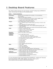
... Advanced Configuration and Power Interface (ACPI) • Wake on USB, PCI, PS/2, LAN, and front panel • Microsoft Windows Vista* Home Basic Edition • Microsoft Windows Vista Home Basic 64-bit edition • Microsoft Windows* XP Professional • Microsoft Windows XP Professional x64 Edition • Microsoft Windows XP Home For more information about Intel Desktop Board D945GCLF2, including the Technical Product Specification (TPS), BIOS updates, and device drivers, go to http://support.intel.com/support/motherboards/desktop/. 9
... Advanced Configuration and Power Interface (ACPI) • Wake on USB, PCI, PS/2, LAN, and front panel • Microsoft Windows Vista* Home Basic Edition • Microsoft Windows Vista Home Basic 64-bit edition • Microsoft Windows* XP Professional • Microsoft Windows XP Professional x64 Edition • Microsoft Windows XP Home For more information about Intel Desktop Board D945GCLF2, including the Technical Product Specification (TPS), BIOS updates, and device drivers, go to http://support.intel.com/support/motherboards/desktop/. 9
Product Guide
Page 12
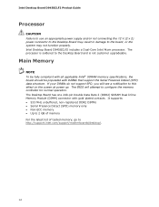
... latest list of tested memory, go to the Desktop Board and is not customer upgradeable. Intel Desktop Board D945GCLF2 Product Guide Processor CAUTION Failure to use an appropriate power supply and/or not connecting the 12 V (2 x 2) power connector to the Desktop Board may not function properly. The BIOS will see a notification to this effect on the screen at power up. Main Memory NOTE To be fully compliant with all applicable Intel® SDRAM memory specifications, the board should...
... latest list of tested memory, go to the Desktop Board and is not customer upgradeable. Intel Desktop Board D945GCLF2 Product Guide Processor CAUTION Failure to use an appropriate power supply and/or not connecting the 12 V (2 x 2) power connector to the Desktop Board may not function properly. The BIOS will see a notification to this effect on the screen at power up. Main Memory NOTE To be fully compliant with all applicable Intel® SDRAM memory specifications, the board should...

Product Guide
Page 13
... processor, memory, and the DMI interconnect. The ICH7 is connected to an audio port and retask the connector via the audio driver. • S/N (signal-to-noise) ratio: 95 dB • Microphone input supporting: ― Stereo microphone ― Microphone boost The subsystem includes the following devices: • Intel 82945GC Express Chipset Graphics and Memory Controller Hub (GMCH) • Intel 82801GB I /O paths. This component also provides integrated graphics capabilities via a 7-pin back panel connector...
... processor, memory, and the DMI interconnect. The ICH7 is connected to an audio port and retask the connector via the audio driver. • S/N (signal-to-noise) ratio: 95 dB • Microphone input supporting: ― Stereo microphone ― Microphone boost The subsystem includes the following devices: • Intel 82945GC Express Chipset Graphics and Memory Controller Hub (GMCH) • Intel 82801GB I /O paths. This component also provides integrated graphics capabilities via a 7-pin back panel connector...
Product Guide
Page 14
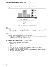
...: Go to power headphones or amplified speakers only. Intel Desktop Board D945GCLF2 Product Guide Figure 2 shows the default assignment of the back panel audio connectors. Back Panel Audio Connectors NOTE The back panel audio line out connector is designed to the following locations for more information about: • Audio drivers and utilities http://support.intel.com/support/motherboards/desktop/ • Installing a front panel audio solution (page 31) Input/Output (I/O) Controller The super I/O controller features the following: • One serial port • One...
...: Go to power headphones or amplified speakers only. Intel Desktop Board D945GCLF2 Product Guide Figure 2 shows the default assignment of the back panel audio connectors. Back Panel Audio Connectors NOTE The back panel audio line out connector is designed to the following locations for more information about: • Audio drivers and utilities http://support.intel.com/support/motherboards/desktop/ • Installing a front panel audio solution (page 31) Input/Output (I/O) Controller The super I/O controller features the following: • One serial port • One...

Product Guide
Page 15
... LAN connector located on Intel's World Wide Web site at http://support.intel.com/support/motherboards/desktop. Table 3. Desktop Board Features LAN Subsystem The LAN, based on the RealTek RTL8111C Ethernet Controller, provides the following functions: • 10/100/1000 Mb/s Gigabit Ethernet LAN • Support for RJ-45 connector with status indicator LEDs • Programmable transit threshold • Configurable EEPROM that contains the MAC address LAN Subsystem Software For LAN software and drivers...
... LAN connector located on Intel's World Wide Web site at http://support.intel.com/support/motherboards/desktop. Table 3. Desktop Board Features LAN Subsystem The LAN, based on the RealTek RTL8111C Ethernet Controller, provides the following functions: • 10/100/1000 Mb/s Gigabit Ethernet LAN • Support for RJ-45 connector with status indicator LEDs • Programmable transit threshold • Configurable EEPROM that contains the MAC address LAN Subsystem Software For LAN software and drivers...
Product Guide
Page 16
... Desktop Board supports two Serial ATA channels (3.0 Gb/s), connecting one PCI add-in the BIOS reverts all USB 2.0 ports to the cable. Intel Desktop Board D945GCLF2 Product Guide Hi-Speed USB 2.0 Support NOTE Computer systems that fully support USB 2.0 transfer rates. The Desktop Board supports up to eight USB 2.0 ports (four ports routed to the back panel and four ports routed to two IDE devices (such as hard drives) • ATAPI-style devices (such as hard disks and optical drives inside the computer. The USB 2.0 ports are backward compatible...
... Desktop Board supports two Serial ATA channels (3.0 Gb/s), connecting one PCI add-in the BIOS reverts all USB 2.0 ports to the cable. Intel Desktop Board D945GCLF2 Product Guide Hi-Speed USB 2.0 Support NOTE Computer systems that fully support USB 2.0 transfer rates. The Desktop Board supports up to eight USB 2.0 ports (four ports routed to the back panel and four ports routed to two IDE devices (such as hard drives) • ATAPI-style devices (such as hard disks and optical drives inside the computer. The USB 2.0 ports are backward compatible...
Product Guide
Page 17
... booted. Desktop Board Features BIOS The BIOS provides the Power-On Self-Test (POST), the BIOS Setup program, the PCI and IDE auto-configuration utilities, and the video BIOS. If both the supervisor and user passwords are set , you must enter either password to run the BIOS Setup program after installing an IDE device. PCI Auto Configuration If you can enter either the supervisor password or the user password to run the BIOS Setup program after you install an IDE device (such as a hard drive) in card. For instructions on resetting the password, see Clearing Passwords...
... booted. Desktop Board Features BIOS The BIOS provides the Power-On Self-Test (POST), the BIOS Setup program, the PCI and IDE auto-configuration utilities, and the video BIOS. If both the supervisor and user passwords are set , you must enter either password to run the BIOS Setup program after installing an IDE device. PCI Auto Configuration If you can enter either the supervisor password or the user password to run the BIOS Setup program after you install an IDE device (such as a hard drive) in card. For instructions on resetting the password, see Clearing Passwords...

Product Guide
Page 18
... the DIMM socket and the PCI bus connector, even though the computer appears to be off and the standby power indicator is standby power to the board. Intel Desktop Board D945GCLF2 Product Guide Power Management Features Power management is implemented at several levels, including: • Advanced Configuration and Power Interface (ACPI) • Hardware support: ― Power connectors ― Fan headers ― +5 V standby power indicator LED ― LAN Wake capabilities ― Wake from USB ― Wake from PS/2 keyboard/mouse...
... the DIMM socket and the PCI bus connector, even though the computer appears to be off and the standby power indicator is standby power to the board. Intel Desktop Board D945GCLF2 Product Guide Power Management Features Power management is implemented at several levels, including: • Advanced Configuration and Power Interface (ACPI) • Hardware support: ― Power connectors ― Fan headers ― +5 V standby power indicator LED ― LAN Wake capabilities ― Wake from USB ― Wake from PS/2 keyboard/mouse...

Product Guide
Page 19
... the Intel Desktop D945GCLF2 web page at http://support.intel.com/support/motherboards/desktop/ LAN Wake Capabilities CAUTION For LAN wake capabilities, the 5 V standby line for the Desktop Board, refer to provide adequate standby current when using this feature can damage the power supply. Wake from USB NOTE Wake from USB requires the use of the computer through a network. USB bus activity wakes the computer from USB. LAN wakeup capabilities enable remote wake-up the computer. The LAN subsystem monitors network traffic...
... the Intel Desktop D945GCLF2 web page at http://support.intel.com/support/motherboards/desktop/ LAN Wake Capabilities CAUTION For LAN wake capabilities, the 5 V standby line for the Desktop Board, refer to provide adequate standby current when using this feature can damage the power supply. Wake from USB NOTE Wake from USB requires the use of the computer through a network. USB bus activity wakes the computer from USB. LAN wakeup capabilities enable remote wake-up the computer. The LAN subsystem monitors network traffic...

Product Guide
Page 21
...safety practices and regulatory compliance required for using an antistatic wrist strap and a conductive foam pad. 2 Installing and Replacing Desktop Board Components This chapter tells you how to: • Install the I/O shield • Install and remove the Desktop Board • Install and remove memory • Connect the IDE cable • Connect the SATA cable • Connect internal headers • Connect chassis fan and power supply cables • Set the BIOS configuration and audio jumpers • Clear passwords • Replace the battery Before You Begin CAUTIONS The procedures...
...safety practices and regulatory compliance required for using an antistatic wrist strap and a conductive foam pad. 2 Installing and Replacing Desktop Board Components This chapter tells you how to: • Install the I/O shield • Install and remove the Desktop Board • Install and remove memory • Connect the IDE cable • Connect the SATA cable • Connect internal headers • Connect chassis fan and power supply cables • Set the BIOS configuration and audio jumpers • Clear passwords • Replace the battery Before You Begin CAUTIONS The procedures...

Product Guide
Page 35
Moving the jumper with the power on may result in the BIOS Setup program. Figure 14. Figure 14 shows the location of the Desktop Board's BIOS configuration jumper block. Table 8 shows the jumper settings for the Setup program modes. 35 BIOS Configuration Jumper Block The three-pin BIOS jumper block enables all board configuration to be done in unreliable computer operation. Installing and Replacing Desktop Board Components Setting the BIOS Configuration Jumper NOTE Always turn off the power and unplug the power cord from the computer before changing a jumper.
Moving the jumper with the power on may result in the BIOS Setup program. Figure 14. Figure 14 shows the location of the Desktop Board's BIOS configuration jumper block. Table 8 shows the jumper settings for the Setup program modes. 35 BIOS Configuration Jumper Block The three-pin BIOS jumper block enables all board configuration to be done in unreliable computer operation. Installing and Replacing Desktop Board Components Setting the BIOS Configuration Jumper NOTE Always turn off the power and unplug the power cord from the computer before changing a jumper.

Product Guide
Page 36
... screen requesting that the board is installed in the event of the Desktop Board's BIOS configuration jumper block. Turn off the computer. Replace the cover, plug in "Before You Begin" on the computer, and allow it to normal mode. 1. Use the arrow keys to save the current values and exit Setup. 10. Press to select Clear Passwords. Jumper Settings for the BIOS Setup Program Modes Jumper Setting Mode Normal (default) (1-2) Description The BIOS uses the current configuration and passwords for booting. Clearing Passwords...
... screen requesting that the board is installed in the event of the Desktop Board's BIOS configuration jumper block. Turn off the computer. Replace the cover, plug in "Before You Begin" on the computer, and allow it to normal mode. 1. Use the arrow keys to save the current values and exit Setup. 10. Press to select Clear Passwords. Jumper Settings for the BIOS Setup Program Modes Jumper Setting Mode Normal (default) (1-2) Description The BIOS uses the current configuration and passwords for booting. Clearing Passwords...

Product Guide
Page 43
.... The Iflash BIOS update file is useful if you can use of Windows-based installation wizards. This runs the update program. 6. Updating the BIOS with the Intel Express BIOS Update utility: 1. The Iflash BIOS update file contains: • New BIOS file • Intel Flash Memory Update Utility 43 The BIOS file is required. Double-click the executable file from the location on your hard drive. (You can access the BIOS Setup program by either using the Iflash BIOS update file. This step is included in this file to a removable USB device. Your...
.... The Iflash BIOS update file is useful if you can use of Windows-based installation wizards. This runs the update program. 6. Updating the BIOS with the Intel Express BIOS Update utility: 1. The Iflash BIOS update file contains: • New BIOS file • Intel Flash Memory Update Utility 43 The BIOS file is required. Double-click the executable file from the location on your hard drive. (You can access the BIOS Setup program by either using the Iflash BIOS update file. This step is included in this file to a removable USB device. Your...

Product Guide
Page 44
... USB flash drive or other bootable USB media. 2. Configure the BIOS or use the F10 key option during POST to boot to http://support.intel.com/support/motherboards/desktop/. 44 however, if an interruption occurs, the BIOS could be extracted locally to your computer supplier or by navigating to the Intel Desktop D945GCLF2 page, click "[view] Latest BIOS updates," and select the Iflash BIOS Update utility file. The Iflash BIOS update files can update the system BIOS from the USB device and manually update...
... USB flash drive or other bootable USB media. 2. Configure the BIOS or use the F10 key option during POST to boot to http://support.intel.com/support/motherboards/desktop/. 44 however, if an interruption occurs, the BIOS could be extracted locally to your computer supplier or by navigating to the Intel Desktop D945GCLF2 page, click "[view] Latest BIOS updates," and select the Iflash BIOS Update utility file. The Iflash BIOS update files can update the system BIOS from the USB device and manually update...

Product Guide
Page 45
... a recoverable error occurs during POST, the BIOS causes the front-panel power LED to blink an error message describing the problem (see Figure 2, B on -off for 0.5 second; Table 10. Table 9. BIOS Front-panel Power LED Blink Codes Type Processor initialization complete POST complete BIOS update in Table 10. pattern repeats until system is powered off Memory error On-off (0.5 second each ) four times, then 3.0 second pause (off blink pattern; These beep codes can...
... a recoverable error occurs during POST, the BIOS causes the front-panel power LED to blink an error message describing the problem (see Figure 2, B on -off for 0.5 second; Table 10. Table 9. BIOS Front-panel Power LED Blink Codes Type Processor initialization complete POST complete BIOS update in Table 10. pattern repeats until system is powered off Memory error On-off (0.5 second each ) four times, then 3.0 second pause (off blink pattern; These beep codes can...


