

Product Specification
Page 5
...1.3.2 Manufacturing Options 13 1.3.3 Board Layouts 14 1.3.4 Block Diagram 18 1.4 Online Support ...19 1.5 Processor ...19 1.6 System Memory ...20 1.6.1 Memory Configurations 22 1.7 Intel® 915G Chipset ...26 1.7.1 Intel 915G Graphics Subsystem 26 1.7.2 USB ...28 1.7.3 IDE Support 28 1.7.4 Real-Time Clock, CMOS... 31 1.9.3 Diskette Drive Controller 32 1.9.4 Keyboard and Mouse Interface 32 1.10 Audio Subsystem ...32 1.10.1 Audio Subsystem Software 33 1.10.2 Audio Connectors 33 1.10.3 Intel® High Definition Audio Subsystem 34 1.11 LAN Subsystem ...35 1.11.1 10/100 Mbits/sec LAN...
...1.3.2 Manufacturing Options 13 1.3.3 Board Layouts 14 1.3.4 Block Diagram 18 1.4 Online Support ...19 1.5 Processor ...19 1.6 System Memory ...20 1.6.1 Memory Configurations 22 1.7 Intel® 915G Chipset ...26 1.7.1 Intel 915G Graphics Subsystem 26 1.7.2 USB ...28 1.7.3 IDE Support 28 1.7.4 Real-Time Clock, CMOS... 31 1.9.3 Diskette Drive Controller 32 1.9.4 Keyboard and Mouse Interface 32 1.10 Audio Subsystem ...32 1.10.1 Audio Subsystem Software 33 1.10.2 Audio Connectors 33 1.10.3 Intel® High Definition Audio Subsystem 34 1.11 LAN Subsystem ...35 1.11.1 10/100 Mbits/sec LAN...

Product Specification
Page 8
.... Thermal Considerations for a One-Color Power LED 75 37. I /O Shield Dimensions 80 28. PCI Interrupt Routing Map 62 19. Intel Desktop Board D915GAV/D915GAG Technical Product Specification 27. Localized High Temperature Zones 84 Tables 1. Feature Summary ...12 3. Manufacturing Options 13 4. .... Component-side Connectors Shown in Figure 20 69 22. ATAPI CD-ROM Connector (Optional 70 24. Front Panel Audio Connector 70 25. Processor Fan Connector 71 30. Chassis Fan Connectors 71 31. Main Power Connector 72 32. Auxiliary Front Panel Power/Sleep...
.... Thermal Considerations for a One-Color Power LED 75 37. I /O Shield Dimensions 80 28. PCI Interrupt Routing Map 62 19. Intel Desktop Board D915GAV/D915GAG Technical Product Specification 27. Localized High Temperature Zones 84 Tables 1. Feature Summary ...12 3. Manufacturing Options 13 4. .... Component-side Connectors Shown in Figure 20 69 22. ATAPI CD-ROM Connector (Optional 70 24. Front Panel Audio Connector 70 25. Processor Fan Connector 71 30. Chassis Fan Connectors 71 31. Main Power Connector 72 32. Auxiliary Front Panel Power/Sleep...

Product Specification
Page 11
... What This Chapter Contains 1.1 PCI Bus Terminology Change 11 1.2 Board Differences ...11 1.3 Overview ...12 1.4 Online Support ...19 1.5 Processor ...19 1.6 System Memory ...20 1.7 Intel® 915G Chipset ...26 1.8 PCI Express Connectors 30 1.9 I/O Controller...31 1.10 Audio Subsystem ...32 1.11 LAN Subsystem ...35 1.12 Hardware Management Subsystem 38 1.13 Power Management ...41 1.14 Trusted Platform...
... What This Chapter Contains 1.1 PCI Bus Terminology Change 11 1.2 Board Differences ...11 1.3 Overview ...12 1.4 Online Support ...19 1.5 Processor ...19 1.6 System Memory ...20 1.7 Intel® 915G Chipset ...26 1.8 PCI Express Connectors 30 1.9 I/O Controller...31 1.10 Audio Subsystem ...32 1.11 LAN Subsystem ...35 1.12 Hardware Management Subsystem 38 1.13 Power Management ...41 1.14 Trusted Platform...
Product Specification
Page 12
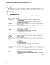
...; D915GAG: microATX Form Factor (9.60 inches by 9.60 inches [243.84 millimeters by 243.84 millimeters]) Support for an Intel® Pentium® 4 processor in an LGA775 socket with an 800 or 533 MHz system bus Memory • Four DDR SDRAM Dual Inline Memory Module (DIMM) sockets ...• Support for DDR 400 MHz and DDR 333 MHz DIMMs • Support for up to 4 GB of system memory Chipset Video Audio Intel® 915G Chipset, consisting of: • Intel...
...; D915GAG: microATX Form Factor (9.60 inches by 9.60 inches [243.84 millimeters by 243.84 millimeters]) Support for an Intel® Pentium® 4 processor in an LGA775 socket with an 800 or 533 MHz system bus Memory • Four DDR SDRAM Dual Inline Memory Module (DIMM) sockets ...• Support for DDR 400 MHz and DDR 333 MHz DIMMs • Support for up to 4 GB of system memory Chipset Video Audio Intel® 915G Chipset, consisting of: • Intel...
Product Specification
Page 18
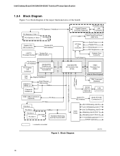
... PCI Express x1 Slot 2 D915GAV only Parallel ATA IDE Connector Parallel ATA IDE Interface LGA775 Processor Socket System Bus (800/533 MHz) PCI Express x16 Interface PCI Express x16 Connector Intel 82915G Graphics and Memory Controller Hub (GMCH) VGA Port Channel A DIMMs (2) Display Interface... 1 PCI Slot 2 PCI Slot 3 PCI Slot 4 D915GAV only SMBus Hardware Monitoring and Fan Control ASIC Serial ATA IDE Interface Serial ATA IDE Connectors (4) Audio Codec Mic In/Retasking Jack B Line In/Retasking Jack C Line Out/Retasking Jack D Retasking Jack E [Port 1] Retasking Jack F [Port 2] CD-...
... PCI Express x1 Slot 2 D915GAV only Parallel ATA IDE Connector Parallel ATA IDE Interface LGA775 Processor Socket System Bus (800/533 MHz) PCI Express x16 Interface PCI Express x16 Connector Intel 82915G Graphics and Memory Controller Hub (GMCH) VGA Port Channel A DIMMs (2) Display Interface... 1 PCI Slot 2 PCI Slot 3 PCI Slot 4 D915GAV only SMBus Hardware Monitoring and Fan Control ASIC Serial ATA IDE Interface Serial ATA IDE Connectors (4) Audio Codec Mic In/Retasking Jack B Line In/Retasking Jack C Line Out/Retasking Jack D Retasking Jack E [Port 1] Retasking Jack F [Port 2] CD-...
Product Specification
Page 19
... Board D915GAV Available configurations for the most up-to support Intel Pentium 4 processors in an LGA775 processor socket with an 800 or 533 MHz system bus. See the Intel web site listed below for the Desktop Board D915GAG Processor data sheets ICH6 addressing Custom splash screens Audio software and utilities LAN software and drivers Visit this World...
... Board D915GAV Available configurations for the most up-to support Intel Pentium 4 processors in an LGA775 processor socket with an 800 or 533 MHz system bus. See the Intel web site listed below for the Desktop Board D915GAG Processor data sheets ICH6 addressing Custom splash screens Audio software and utilities LAN software and drivers Visit this World...

Product Specification
Page 20
... and DDR 333 MHz SDRAM DIMMs Table 6 lists the supported system bus frequency and memory speed combinations. DDR 400 DDR 333 (Note) The processor's system bus frequency must be... 800 MHz 800 or 533 MHz Note: When using an 800 MHz system bus frequency.... • 4 GB maximum total system memory. NOTES • Remove the PCI Express x16 video card before installing or upgrading memory to optimize system throughput. If non-SPD memory is clocked at 320 MHz. Intel Desktop Board D915GAV/D915GAG Technical Product Specification 1.6 System Memory The boards have four DIMM sockets and...
... and DDR 333 MHz SDRAM DIMMs Table 6 lists the supported system bus frequency and memory speed combinations. DDR 400 DDR 333 (Note) The processor's system bus frequency must be... 800 MHz 800 or 533 MHz Note: When using an 800 MHz system bus frequency.... • 4 GB maximum total system memory. NOTES • Remove the PCI Express x16 video card before installing or upgrading memory to optimize system throughput. If non-SPD memory is clocked at 320 MHz. Intel Desktop Board D915GAV/D915GAG Technical Product Specification 1.6 System Memory The boards have four DIMM sockets and...

Product Specification
Page 28
... to the cable. The Parallel ATA IDE interface supports the following modes: • Programmed I/O (PIO): processor controls data transfer. • 8237-style DMA: DMA offloads the processor, supporting transfer rates of up to 16 MB/sec. • Ultra DMA: DMA protocol on IDE bus... Product Specification 1.7.1.4 Configuration Modes A list of supported modes for the Intel GMA900 graphics controller is available as follows: • Four ports are implemented with dual stacked back panel connectors adjacent to the audio connectors • Four ports are routed to two separate front panel ...
... to the cable. The Parallel ATA IDE interface supports the following modes: • Programmed I/O (PIO): processor controls data transfer. • 8237-style DMA: DMA offloads the processor, supporting transfer rates of up to 16 MB/sec. • Ultra DMA: DMA protocol on IDE bus... Product Specification 1.7.1.4 Configuration Modes A list of supported modes for the Intel GMA900 graphics controller is available as follows: • Four ports are implemented with dual stacked back panel connectors adjacent to the audio connectors • Four ports are routed to two separate front panel ...

Product Specification
Page 37
... bus slot 2: • Monitoring of system firmware progress events, including: ⎯ BIOS present ⎯ Primary processor initialization ⎯ Memory initialization ⎯ Video initialization ⎯ PCI resource configuration ⎯ Hard-disk initialization ⎯ User authentication ⎯ Starting operating system ...boot process • Monitoring of system firmware error events, including: ⎯ Memory missing ⎯ Memory failure ⎯ No video device ⎯ Keyboard failure ⎯ Hard-disk failure ⎯ No boot media • Boot options to boot from different ...
... bus slot 2: • Monitoring of system firmware progress events, including: ⎯ BIOS present ⎯ Primary processor initialization ⎯ Memory initialization ⎯ Video initialization ⎯ PCI resource configuration ⎯ Hard-disk initialization ⎯ User authentication ⎯ Starting operating system ...boot process • Monitoring of system firmware error events, including: ⎯ Memory missing ⎯ Memory failure ⎯ No video device ⎯ Keyboard failure ⎯ Hard-disk failure ⎯ No boot media • Boot options to boot from different ...

Product Specification
Page 38
...: • Internal ambient temperature sensor • Two remote thermal diode sensors for direct monitoring of processor temperature and ambient temperature sensing • Power supply monitoring of the fan connectors and sensors for Management (WfM) specification. Intel Desktop Board D915GAV/D915GAG Technical Product Specification 1.11.4 LAN Subsystem Software LAN software and drivers are...
...: • Internal ambient temperature sensor • Two remote thermal diode sensors for direct monitoring of processor temperature and ambient temperature sensing • Power supply monitoring of the fan connectors and sensors for Management (WfM) specification. Intel Desktop Board D915GAV/D915GAG Technical Product Specification 1.11.4 LAN Subsystem Software LAN software and drivers are...

Product Specification
Page 39
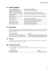
Thermal Monitoring for the D915GAV board. 13 3 1 A CB 4 1 D 13 1 3 Item A B C D E F G H HG F E OM16669 Description Thermal diode, located on processor die Remote ambient temperature sensor Ambient temperature sensor, internal to hardware monitoring and fan control ASIC Processor fan Rear chassis fan 1 Front chassis fan ATX fan (optional) Rear chassis fan 2 Figure 14. Product Description 1.12.2 Thermal Monitoring Figure 14 shows the location of the sensors and fan connectors for D915GAV Board 39
Thermal Monitoring for the D915GAV board. 13 3 1 A CB 4 1 D 13 1 3 Item A B C D E F G H HG F E OM16669 Description Thermal diode, located on processor die Remote ambient temperature sensor Ambient temperature sensor, internal to hardware monitoring and fan control ASIC Processor fan Rear chassis fan 1 Front chassis fan ATX fan (optional) Rear chassis fan 2 Figure 14. Product Description 1.12.2 Thermal Monitoring Figure 14 shows the location of the sensors and fan connectors for D915GAV Board 39

Product Specification
Page 40
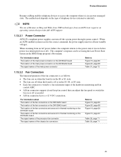
Intel Desktop Board D915GAV/D915GAG Technical Product Specification Figure 15 shows the location of the sensors and fan connectors for D915GAG Board 40 Thermal Monitoring for the D915GAG board. 3 1 A CB 4 1 D 1 3 Item A B C D E F F E OM16659 Description Thermal diode, located on processor die Remote ambient temperature sensor Ambient temperature sensor, internal to hardware monitoring and fan control ASIC Processor fan Rear chassis fan Front chassis fan Figure 15.
Intel Desktop Board D915GAV/D915GAG Technical Product Specification Figure 15 shows the location of the sensors and fan connectors for D915GAG Board 40 Thermal Monitoring for the D915GAG board. 3 1 A CB 4 1 D 1 3 Item A B C D E F F E OM16659 Description Thermal diode, located on processor die Remote ambient temperature sensor Ambient temperature sensor, internal to hardware monitoring and fan control ASIC Processor fan Rear chassis fan Front chassis fan Figure 15.

Product Specification
Page 43
working Processor States C0 - stop grant G1 - S4 - Soft off AC power is disconnected from the computer. No power to disk. no power except for wake-up ... < 5 W (Note 2) Power < 5 W (Note 2) D3 - Service can be performed safely. Dependent on the system configuration, including add-in the system. 43 working state Sleeping States S0 - Processor stopped C1 - sleeping state G1 - S3 - Suspend to the system. D3 - D3 - D3 - No power to disk. working Device States D0 - mechanical off . Context not...
working Processor States C0 - stop grant G1 - S4 - Soft off AC power is disconnected from the computer. No power to disk. no power except for wake-up ... < 5 W (Note 2) Power < 5 W (Note 2) D3 - Service can be performed safely. Dependent on the system configuration, including add-in the system. 43 working state Sleeping States S0 - Processor stopped C1 - sleeping state G1 - S3 - Suspend to the system. D3 - D3 - D3 - No power to disk. working Device States D0 - mechanical off . Context not...
Product Specification
Page 45
... monitoring on the D915GAV board The location of the fan connectors and sensors for thermal monitoring on the D915GAG board The signal names of the processor fan connector The signal names of the chassis fan connectors Refer to Figure 19, page 66 Figure 20, page 68 Table 31, page 72 1.13...
... monitoring on the D915GAV board The location of the fan connectors and sensors for thermal monitoring on the D915GAG board The signal names of the processor fan connector The signal names of the chassis fan connectors Refer to Figure 19, page 66 Figure 20, page 68 Table 31, page 72 1.13...

Product Specification
Page 71
... (Optional) Pin Signal Name 1 SCSI_ACT# 2 No connect Table 28. Table 30. Chassis Fan Connectors Pin Signal Name 1 Control 2 +12 V 3 Tach 71 Technical Reference Table 27. Processor Fan Connector Pin Signal Name 1 Ground 2 +12 V 3 FAN_TACH 4 FAN_CONTROL 2.8.2.1 Chassis Fan Connectors The D915GAV board has three standard and one optional chassis fan connectors: •...
... (Optional) Pin Signal Name 1 SCSI_ACT# 2 No connect Table 28. Table 30. Chassis Fan Connectors Pin Signal Name 1 Control 2 +12 V 3 Tach 71 Technical Reference Table 27. Processor Fan Connector Pin Signal Name 1 Ground 2 +12 V 3 FAN_TACH 4 FAN_CONTROL 2.8.2.1 Chassis Fan Connectors The D915GAV board has three standard and one optional chassis fan connectors: •...

Product Specification
Page 72
...9135; The alternate power connector Table 31. This connector is to use three connectors to provide power to do so will be used on Intel Desktop boards. a 1 x 4 connector. This connector provides power directly to 144 W of power from booting. • Alternate power... - The 2 x 12 main power cable can provide up to the processor voltage regulator and must always be unconnected. 72 a 2 x 12 connector. Intel Desktop Board D915GAV/D915GAG Technical Product Specification 2.8.2.2 Power Supply Connectors The board has three power supply connectors:...
...9135; The alternate power connector Table 31. This connector is to use three connectors to provide power to do so will be used on Intel Desktop boards. a 1 x 4 connector. This connector provides power directly to 144 W of power from booting. • Alternate power... - The 2 x 12 main power cable can provide up to the processor voltage regulator and must always be unconnected. 72 a 2 x 12 connector. Intel Desktop Board D915GAV/D915GAG Technical Product Specification 2.8.2.2 Power Supply Connectors The board has three power supply connectors:...

Product Specification
Page 77
... is set to recover the BIOS configuration. Location of the jumper block on the D915GAV board. (The jumper is powered-up, the BIOS compares the processor version and the microcode version in the same location on . Recovery None 1 The BIOS attempts to configure mode and the computer is in the BIOS...
... is set to recover the BIOS configuration. Location of the jumper block on the D915GAV board. (The jumper is powered-up, the BIOS compares the processor version and the microcode version in the same location on . Recovery None 1 The BIOS attempts to configure mode and the computer is in the BIOS...

Product Specification
Page 81
...• A fully loaded D915GAG board (all active components within the board that is dependent on specific processor values or memory configurations but are designed to a particular processor speed. Table 39. Maximum values assume a load placed on the minimum and maximum current draw possible ... a 500 mA current draw per USB port. The selection of the boards. Use the datasheets for both boards is similar to the processor, memory, and USB ports. Technical Reference 2.11 Electrical Considerations 2.11.1 DC Loading Table 39 lists the DC loading characteristics of a ...
...• A fully loaded D915GAG board (all active components within the board that is dependent on specific processor values or memory configurations but are designed to a particular processor speed. Table 39. Maximum values assume a load placed on the minimum and maximum current draw possible ... a 500 mA current draw per USB port. The selection of the boards. Use the datasheets for both boards is similar to the processor, memory, and USB ports. Technical Reference 2.11 Electrical Considerations 2.11.1 DC Loading Table 39 lists the DC loading characteristics of a ...

Product Specification
Page 82
... on configurations chosen by the integrator. Additional power required will halt fan operation. Table 40. Intel Desktop Board D915GAV/D915GAG Technical Product Specification 2.11.3 Fan Connector Current Capability CAUTION The processor fan must be connected to the processor fan connector, not to a chassis fan connector. The total amount of standby current required depends...
... on configurations chosen by the integrator. Additional power required will halt fan operation. Table 40. Intel Desktop Board D915GAV/D915GAG Technical Product Specification 2.11.3 Fan Connector Current Capability CAUTION The processor fan must be connected to the processor fan connector, not to a chassis fan connector. The total amount of standby current required depends...

Product Specification
Page 83
... the following the instructions presented in this document will result in Section 2.14. 83 Processor Heatsink for determining the adequacy of 38 oC at the processor fan inlet is a requirement. Intel makes no warranties or representations that have been tested with Intel desktop boards please refer to exceed their maximum case temperature and malfunction.
... the following the instructions presented in this document will result in Section 2.14. 83 Processor Heatsink for determining the adequacy of 38 oC at the processor fan inlet is a requirement. Intel makes no warranties or representations that have been tested with Intel desktop boards please refer to exceed their maximum case temperature and malfunction.


