

Product Specification
Page 7
... and Configuration 96 3.8.2 Intel Rapid BIOS Boot 96 3.9 BIOS Security Features 97 4 Error Messages and Beep Codes 4.1 BIOS Error Messages 99 4.2 Port 80h POST Codes 101 4.3 Bus Initialization Checkpoints 105 4.4 Speaker...106 4.5 BIOS Beep Codes...106 Figures 1. LAN Connector LED Locations 37 14. Detailed System Memory Address Map 56 18. Contents 3.6 BIOS Updates ...94 3.6.1 Language Support 94 3.6.2 Custom Splash Screen 94 3.7 Boot Options ...95 3.7.1 CD-ROM Boot 95 3.7.2 Network Boot 95 3.7.3 Booting Without Attached Devices 95 3.7.4 Changing the Default Boot Device...
... and Configuration 96 3.8.2 Intel Rapid BIOS Boot 96 3.9 BIOS Security Features 97 4 Error Messages and Beep Codes 4.1 BIOS Error Messages 99 4.2 Port 80h POST Codes 101 4.3 Bus Initialization Checkpoints 105 4.4 Speaker...106 4.5 BIOS Beep Codes...106 Figures 1. LAN Connector LED Locations 37 14. Detailed System Memory Address Map 56 18. Contents 3.6 BIOS Updates ...94 3.6.1 Language Support 94 3.6.2 Custom Splash Screen 94 3.7 Boot Options ...95 3.7.1 CD-ROM Boot 95 3.7.2 Network Boot 95 3.7.3 Booting Without Attached Devices 95 3.7.4 Changing the Default Boot Device...

Product Specification
Page 8
.... Supported System Bus Frequency and Memory Speed Combinations 20 7. Component-side Connectors Shown in Figure 18 65 20. Processor Fan Connector 71 30. States for Components 85 42. I /O Shield Dimensions 80 28. Serial Port B Connector (optional 70 26. PCI Interrupt Routing Map 62 19. Front Panel Audio Connector 70 25. Supported Memory Configurations 21 8. Effects of Board Differences 11 2. Chassis Fan Connectors 71 31. LAN Connector LED States 36 9. Main Power Connector 72 32. Summary of Pressing the Power Switch 42 11. Intel Desktop Board...
.... Supported System Bus Frequency and Memory Speed Combinations 20 7. Component-side Connectors Shown in Figure 18 65 20. Processor Fan Connector 71 30. States for Components 85 42. I /O Shield Dimensions 80 28. Serial Port B Connector (optional 70 26. PCI Interrupt Routing Map 62 19. Front Panel Audio Connector 70 25. Supported Memory Configurations 21 8. Effects of Board Differences 11 2. Chassis Fan Connectors 71 31. LAN Connector LED States 36 9. Main Power Connector 72 32. Summary of Pressing the Power Switch 42 11. Intel Desktop Board...

Product Specification
Page 11
... rear chassis 2 LAN configuration 10/100 Mbits/sec LAN subsystem only D915GAG microATX Two One Two: front chassis and rear chassis One of Intel® Desktop Boards used an add-in card connector referred to as PCI. Two in Table 1. 1 Product Description What This Chapter Contains 1.1 PCI Bus Terminology Change 11 1.2 Board Differences ...11 1.3 Overview ...12 1.4 Online Support ...19 1.5 Processor ...19 1.6 System Memory ...20 1.7 Intel® 915G Chipset ...26 1.8 PCI Express Connectors 30 1.9 I/O Controller...31 1.10 Audio...
... rear chassis 2 LAN configuration 10/100 Mbits/sec LAN subsystem only D915GAG microATX Two One Two: front chassis and rear chassis One of Intel® Desktop Boards used an add-in card connector referred to as PCI. Two in Table 1. 1 Product Description What This Chapter Contains 1.1 PCI Bus Terminology Change 11 1.2 Board Differences ...11 1.3 Overview ...12 1.4 Online Support ...19 1.5 Processor ...19 1.6 System Memory ...20 1.7 Intel® 915G Chipset ...26 1.8 PCI Express Connectors 30 1.9 I/O Controller...31 1.10 Audio...
Product Specification
Page 13
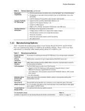
... configurations for the Desktop Boards D915GAV and D915GAG Refer to you. Please contact your Intel representative to determine which manufacturing options are available to Section 1.4, page 19 13 Serial Port B Second serial port accessible via a connector on the component side of the board) that provides digital audio signals in card connector (both boards) Instantly Available PC Technology • Support for PCI Local Bus Specification Revision 2.2 • Support for use the same LED as the onboard IDE controller...
... configurations for the Desktop Boards D915GAV and D915GAG Refer to you. Please contact your Intel representative to determine which manufacturing options are available to Section 1.4, page 19 13 Serial Port B Second serial port accessible via a connector on the component side of the board) that provides digital audio signals in card connector (both boards) Instantly Available PC Technology • Support for PCI Local Bus Specification Revision 2.2 • Support for use the same LED as the onboard IDE controller...
Product Specification
Page 18
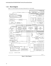
...Intel Desktop Board D915GAV/D915GAG Technical Product Specification 1.3.4 Block Diagram Figure 3 is a block diagram of the major functional areas of the boards. PCI Express x1 Interface PCI Express x1 Slot 1 PCI Express x1 Slot 2 D915GAV only Parallel ATA IDE Connector Parallel ATA IDE Interface LGA775 Processor Socket System Bus (800/533 MHz) PCI Express x16 Interface PCI Express x16 Connector Intel 82915G Graphics and Memory Controller Hub (GMCH) VGA Port Channel A DIMMs (2) Display Interface Dual-Channel Memory Bus SMBus Channel B DIMMs (2) Gigabit Ethernet Controller (Optional...
...Intel Desktop Board D915GAV/D915GAG Technical Product Specification 1.3.4 Block Diagram Figure 3 is a block diagram of the major functional areas of the boards. PCI Express x1 Interface PCI Express x1 Slot 1 PCI Express x1 Slot 2 D915GAV only Parallel ATA IDE Connector Parallel ATA IDE Interface LGA775 Processor Socket System Bus (800/533 MHz) PCI Express x16 Interface PCI Express x16 Connector Intel 82915G Graphics and Memory Controller Hub (GMCH) VGA Port Channel A DIMMs (2) Display Interface Dual-Channel Memory Bus SMBus Channel B DIMMs (2) Gigabit Ethernet Controller (Optional...
Product Specification
Page 26
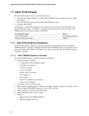
...) card support flat panel displays up to http://developer.intel.com/ Chapter 2 1.7.1 Intel 915G Graphics Subsystem The Intel 915G chipset contains two separate, mutually exclusive graphics options. The ICH6 is used, or a PCI Express x16 add-in card is installed, the GMA900 graphics controller is a centralized controller for the board's I /O Controller Hub (ICH6) with DMI interconnect • Firmware Hub (FWH) The GMCH is disabled. 1.7.1.1 Intel® GMA900 Graphics Controller The Intel GMA900 graphics controller features the following devices: • Intel 82915G Graphics Memory...
...) card support flat panel displays up to http://developer.intel.com/ Chapter 2 1.7.1 Intel 915G Graphics Subsystem The Intel 915G chipset contains two separate, mutually exclusive graphics options. The ICH6 is used, or a PCI Express x16 add-in card is installed, the GMA900 graphics controller is a centralized controller for the board's I /O Controller Hub (ICH6) with DMI interconnect • Firmware Hub (FWH) The GMCH is disabled. 1.7.1.1 Intel® GMA900 Graphics Controller The Intel GMA900 graphics controller features the following devices: • Intel 82915G Graphics Memory...
Product Specification
Page 30
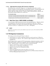
... battery (CR2032) powers the real-time clock and CMOS memory. When the computer is not plugged into CMOS RAM at 25 ºC with the PCI Power Management Event (PME) mechanism defined in hard drive controller or the onboard IDE controller (Parallel ATA or Serial ATA). The x1 interfaces support simultaneous transfer speeds up to use the same LED as the onboard IDE controller. For information about The location of the SCSI hard drive activity LED connector on the D915GAV board...
... battery (CR2032) powers the real-time clock and CMOS memory. When the computer is not plugged into CMOS RAM at 25 ºC with the PCI Power Management Event (PME) mechanism defined in hard drive controller or the onboard IDE controller (Parallel ATA or Serial ATA). The x1 interfaces support simultaneous transfer speeds up to use the same LED as the onboard IDE controller. For information about The location of the SCSI hard drive activity LED connector on the D915GAV board...

Product Specification
Page 52
... does not restore any password changes. 1.14.7 Recovery Procedures 1.14.7.1 Recovering from Hard Disk Failure Restore the latest hard drive image from the previously created Recovery Archives. 1. The key archive should be manually backed up all new and updated keys associated with migratable keys. These passwords should be reset without the original text. Replace the desktop board with the Infineon Security Platform Software (Owner, Emergency Recovery Token, and User passwords) and Wave Systems...
... does not restore any password changes. 1.14.7 Recovery Procedures 1.14.7.1 Recovering from Hard Disk Failure Restore the latest hard drive image from the previously created Recovery Archives. 1. The key archive should be manually backed up all new and updated keys associated with migratable keys. These passwords should be reset without the original text. Replace the desktop board with the Infineon Security Platform Software (Owner, Emergency Recovery Token, and User passwords) and Wave Systems...

Product Specification
Page 53
... screen, and select Restore TPM Keys. 10. Restore the configuration jumper on . 4. It may allow the migratable keys to be able to pins 2-3. 3. To restore access to the EMBASSY Trust Suite, right mouse click on the board to access previously encrypted files. 1.14.8 Clearing Trusted Platform Module Ownership WARNING Disconnect the desktop board's power supply from its AC power source before you connect or disconnect cables, or install or remove...
... screen, and select Restore TPM Keys. 10. Restore the configuration jumper on . 4. It may allow the migratable keys to be able to pins 2-3. 3. To restore access to the EMBASSY Trust Suite, right mouse click on the board to access previously encrypted files. 1.14.8 Clearing Trusted Platform Module Ownership WARNING Disconnect the desktop board's power supply from its AC power source before you connect or disconnect cables, or install or remove...
Product Specification
Page 56
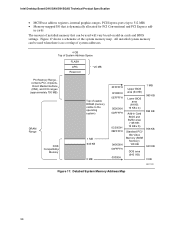
... 0F0000H 0EFFFFH 0E0000H 0DFFFFH 0C0000H 0BFFFFH 0A0000H 09FFFFH 00000H Upper BIOS area (64 KB) Lower BIOS area (64 KB; 16 KB x 4) Add-in cards and BIOS settings. Intel Desktop Board D915GAV/D915GAG Technical Product Specification • MCH base address registers, internal graphics ranges, PCI Express ports (up to 512 MB) • Memory-mapped I/O that can be used when there is dynamically allocated for PCI Conventional and PCI Express add-
... 0F0000H 0EFFFFH 0E0000H 0DFFFFH 0C0000H 0BFFFFH 0A0000H 09FFFFH 00000H Upper BIOS area (64 KB) Lower BIOS area (64 KB; 16 KB x 4) Add-in cards and BIOS settings. Intel Desktop Board D915GAV/D915GAG Technical Product Specification • MCH base address registers, internal graphics ranges, PCI Express ports (up to 512 MB) • Memory-mapped I/O that can be used when there is dynamically allocated for PCI Conventional and PCI Express add-

Product Specification
Page 59
... x16 graphics port (Note 1) Integrated graphics controller Integrated graphics controller Intel High Definition Audio Controller PCI Express port 1 (PCI Express x1 bus connector 1) PCI Express port 2 (Gigabit LAN controller, if present) PCI Express port 3 (PCI Express x1 bus connector 2) (Note 2) 00 1C 03 PCI Express port 4 (not used . 59 Present only when a PCI Express x16 graphics card is dynamic and can change based on the D915GAG board. 3. Bus number is installed. 2. Technical Reference 2.5 PCI Configuration Space Map Table 16. Not present on add-in cards used ) 00 1D 00 USB...
... x16 graphics port (Note 1) Integrated graphics controller Integrated graphics controller Intel High Definition Audio Controller PCI Express port 1 (PCI Express x1 bus connector 1) PCI Express port 2 (Gigabit LAN controller, if present) PCI Express port 3 (PCI Express x1 bus connector 2) (Note 2) 00 1C 03 PCI Express port 4 (not used . 59 Present only when a PCI Express x16 graphics card is dynamic and can change based on the D915GAG board. 3. Bus number is installed. 2. Technical Reference 2.5 PCI Configuration Space Map Table 16. Not present on add-in cards used ) 00 1D 00 USB...
Product Specification
Page 91
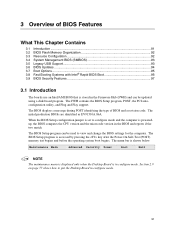
... boot begins. Maintenance Main Advanced Security Power Boot Exit NOTE The maintenance menu is displayed only when the Desktop Board is stored in configure mode. 3 Overview of BIOS and a revision code. The BIOS displays a message during POST identifying the type of BIOS Features What This Chapter Contains 3.1 Introduction ...91 3.2 BIOS Flash Memory Organization 92 3.3 Resource Configuration 92 3.4 System Management BIOS (SMBIOS 93 3.5 Legacy USB Support...93 3.6 BIOS Updates ...94 3.7 Boot Options ...95 3.8 Fast Booting Systems with Intel® Rapid BIOS Boot 96 3.9 BIOS...
... boot begins. Maintenance Main Advanced Security Power Boot Exit NOTE The maintenance menu is displayed only when the Desktop Board is stored in configure mode. 3 Overview of BIOS and a revision code. The BIOS displays a message during POST identifying the type of BIOS Features What This Chapter Contains 3.1 Introduction ...91 3.2 BIOS Flash Memory Organization 92 3.3 Resource Configuration 92 3.4 System Management BIOS (SMBIOS 93 3.5 Legacy USB Support...93 3.6 BIOS Updates ...94 3.7 Boot Options ...95 3.8 Fast Booting Systems with Intel® Rapid BIOS Boot 96 3.9 BIOS...
Product Specification
Page 92
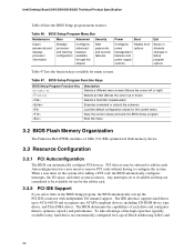
... IDE Support If you select Auto in cards. The BIOS determines the capabilities of the high capacities typically available today, hard drives are considered to configure the system. The IDE interface supports hard drives up or down) Selects a field (Not implemented) Executes command or selects the submenu Load the default configuration values for menu screens. BIOS Setup Program Menu Bar Maintenance Main Advanced Security Clears passwords and displays processor information Displays processor and memory configuration Configures advanced features available through the chipset Sets...
... IDE Support If you select Auto in cards. The BIOS determines the capabilities of the high capacities typically available today, hard drives are considered to configure the system. The IDE interface supports hard drives up or down) Selects a field (Not implemented) Executes command or selects the submenu Load the default configuration values for menu screens. BIOS Setup Program Menu Bar Maintenance Main Advanced Security Clears passwords and displays processor information Displays processor and memory configuration Configures advanced features available through the chipset Sets...
Product Specification
Page 93
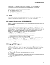
... management software to install an operating system that supports USB. By default, Legacy USB support is set to the computer, legacy support is enabled by specifying manual configuration in a managed network. To use SMBIOS. The MIF database defines the data and provides the method for such operating systems. Using this information. For example, do not connect an ATA hard drive as an ATAPI master device. The BIOS enables applications such as follows: 1. Legacy USB support is disabled...
... management software to install an operating system that supports USB. By default, Legacy USB support is set to the computer, legacy support is enabled by specifying manual configuration in a managed network. To use SMBIOS. The MIF database defines the data and provides the method for such operating systems. Using this information. For example, do not connect an ATA hard drive as an ATAPI master device. The BIOS enables applications such as follows: 1. Legacy USB support is disabled...

Product Specification
Page 95
... a default boot device Exits the menu, saves changes, and boots from the LAN. The fourth device is supported in card with a remote boot ROM installed. This selection allows booting from a diskette drive, hard drives, CD-ROM, or the network. Under the Boot menu in the BIOS Setup program, ATAPI CD-ROM is listed as set to Full. 3.7.3 Booting Without Attached Devices For use this key during POST causes a boot device menu to be set in the CD-ROM drive, the system will attempt to boot from CD-ROM is disabled...
... a default boot device Exits the menu, saves changes, and boots from the LAN. The fourth device is supported in card with a remote boot ROM installed. This selection allows booting from a diskette drive, hard drives, CD-ROM, or the network. Under the Boot menu in the BIOS Setup program, ATAPI CD-ROM is listed as set to Full. 3.7.3 Booting Without Attached Devices For use this key during POST causes a boot device menu to be set in the CD-ROM drive, the system will attempt to boot from CD-ROM is disabled...

Product Specification
Page 96
... the POST execution time. • Disable Quiet Boot, which enables the system to four seconds of option ROM boot time. In the Boot Menu: • Set the hard disk drive as logo displays, screen repaints, or mode changes in the Drive Configuration Submenu of the BIOS Setup program). 96 This could save several seconds of the logo splash screen. If this condition should occur, it will not be initialized at all. Intel Desktop Board D915GAV...
... the POST execution time. • Disable Quiet Boot, which enables the system to four seconds of option ROM boot time. In the Boot Menu: • Set the hard disk drive as logo displays, screen repaints, or mode changes in the Drive Configuration Submenu of the BIOS Setup program). 96 This could save several seconds of the logo splash screen. If this condition should occur, it will not be initialized at all. Intel Desktop Board D915GAV...

Product Specification
Page 100
...a problem with the system. On Board Parity Error A parity error occurred in onboard memory at an unknown address. Parity Error A parity error occurred in onboard memory. User must enter Setup. 100 This error is connected properly. BIOS Error Messages (continued) Error Message Explanation Update OK! Keyboard Error Error in the keyboard connection. Memory Size Increased Memory size has increased since the last boot. If no memory was invalid and has been updated. NVRAM/CMOS/PASSWORD cleared by an address. NVRAM was added or removed then memory...
...a problem with the system. On Board Parity Error A parity error occurred in onboard memory at an unknown address. Parity Error A parity error occurred in onboard memory. User must enter Setup. 100 This error is connected properly. BIOS Error Messages (continued) Error Message Explanation Update OK! Keyboard Error Error in the keyboard connection. Memory Size Increased Memory size has increased since the last boot. If no memory was invalid and has been updated. NVRAM/CMOS/PASSWORD cleared by an address. NVRAM was added or removed then memory...

Product Specification
Page 101
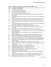
... I/O port 80h. Compressed recovery code is Disabled. Displaying the POST-codes requires a PCI bus add-in F000 shadow RAM. Table 51 defines the uncompressed INIT code checkpoints, Table 52 describes the boot block recovery code checkpoints, and Table 53 lists the runtime code uncompressed in card, often called a POST card. Keyboard controller BAT test, CPU ID saved, and going to recovery code in the tables because that code applies to boot from floppy. Control is initialized. Uncompress the main BIOS...
... I/O port 80h. Compressed recovery code is Disabled. Displaying the POST-codes requires a PCI bus add-in F000 shadow RAM. Table 51 defines the uncompressed INIT code checkpoints, Table 52 describes the boot block recovery code checkpoints, and Table 53 lists the runtime code uncompressed in card, often called a POST card. Keyboard controller BAT test, CPU ID saved, and going to recovery code in the tables because that code applies to boot from floppy. Control is initialized. Uncompress the main BIOS...
Product Specification
Page 103
... interrupt controller. Keyboard test started . To enter in real mode. Memory wrap around at 0:0. Going to find out amount of POST Operation To prepare the descriptor tables. Memory below 1M cleared. (SOFT RESET) Going to clear memory above 1M cleared. (SOFT RESET) Going to check point # 52h). Memory testing/initialization below 1M found . Memory size display adjusted due to start DMA and interrupt controller test. Going to save the memory size. (Go...
... interrupt controller. Keyboard test started . To enter in real mode. Memory wrap around at 0:0. Going to find out amount of POST Operation To prepare the descriptor tables. Memory below 1M cleared. (SOFT RESET) Going to clear memory above 1M cleared. (SOFT RESET) Going to check point # 52h). Memory testing/initialization below 1M found . Memory size display adjusted due to start DMA and interrupt controller test. Going to save the memory size. (Go...
Product Specification
Page 106
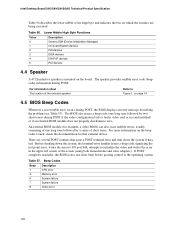
... card installed) or if an external ROM module does not properly checksum to initialize the video and writes the error in the upper left corner of the high byte and indicates the bus on the board. Intel Desktop Board D915GAV/D915GAG Technical Product Specification Table 56 describes the lower nibble of the screen (using both monochrome and color adapters). Table 57. Beep Codes Beep 1 3 6 7 8 Description CPU error Memory error System failure System failure Video error...
... card installed) or if an external ROM module does not properly checksum to initialize the video and writes the error in the upper left corner of the high byte and indicates the bus on the board. Intel Desktop Board D915GAV/D915GAG Technical Product Specification Table 56 describes the lower nibble of the screen (using both monochrome and color adapters). Table 57. Beep Codes Beep 1 3 6 7 8 Description CPU error Memory error System failure System failure Video error...


