
Product Specification
Page 5
... Description 1.1 Overview 9 1.1.1 Feature Summary 9 1.1.2 Board Layout 11 1.1.3 Block Diagram 13 1.2 Legacy Considerations 14 1.3 Online Support 14 1.4 Processor 14 1.5 System Memory 15 1.5.1 Memory Configurations 16 1.6 Intel® P55 Express Chipset 18 1.6.1 USB 18 1.6.2 SATA Interfaces 19 1.7 Discrete SATA Controller 20 1.7.1 eSATA Support 20 1.8 Real-Time Clock Subsystem 20 1.9 Legacy I/O Controller 21 1.9.1 Consumer Infrared (CIR...
... Description 1.1 Overview 9 1.1.1 Feature Summary 9 1.1.2 Board Layout 11 1.1.3 Block Diagram 13 1.2 Legacy Considerations 14 1.3 Online Support 14 1.4 Processor 14 1.5 System Memory 15 1.5.1 Memory Configurations 16 1.6 Intel® P55 Express Chipset 18 1.6.1 USB 18 1.6.2 SATA Interfaces 19 1.7 Discrete SATA Controller 20 1.7.1 eSATA Support 20 1.8 Real-Time Clock Subsystem 20 1.9 Legacy I/O Controller 21 1.9.1 Consumer Infrared (CIR...

Product Specification
Page 9
...Chipset Audio ATX (12.00 inches by 9.60 inches [304.80 millimeters by 243.84 millimeters]) • Intel® Core™ i7 and Intel® Core™ i5 processors in an LGA1156 socket: ― 1 x16 PCIe 2.0 Graphics interface (operates in x8 mode when second slot is populated) ― 1 x8 PCIe 2.0 Graphics interface ― Two DDR3... memory channels • Four 240-pin DDR3 SDRAM Dual Inline Memory Module (DIMM) sockets • Support for DDR3 1600 MHz, DDR3 1333 MHz, and DDR3 1066 MHz DIMMs • Support for 1 Gb and 2 Gb memory technology • Support for up to 16 GB of...
...Chipset Audio ATX (12.00 inches by 9.60 inches [304.80 millimeters by 243.84 millimeters]) • Intel® Core™ i7 and Intel® Core™ i5 processors in an LGA1156 socket: ― 1 x16 PCIe 2.0 Graphics interface (operates in x8 mode when second slot is populated) ― 1 x8 PCIe 2.0 Graphics interface ― Two DDR3... memory channels • Four 240-pin DDR3 SDRAM Dual Inline Memory Module (DIMM) sockets • Support for DDR3 1600 MHz, DDR3 1333 MHz, and DDR3 1066 MHz DIMMs • Support for 1 Gb and 2 Gb memory technology • Support for up to 16 GB of...

Product Specification
Page 14
... Wide Web site: http://www.intel.com/products/motherboard/DP55KG/index.htm http://support.intel.com/support/motherboards/desktop http://www.intel.com/products/motherboard/DP55KG/index.htm http://processormatch.intel.com http://www.intel.com/products/desktop/chipsets/index.htm http://downloadcenter.intel.com http://support.intel.com/support/motherboards/desktop/sb/CS025414.htm http://www.intel.com/support/go/buildit 1.4 Processor...
... Wide Web site: http://www.intel.com/products/motherboard/DP55KG/index.htm http://support.intel.com/support/motherboards/desktop http://www.intel.com/products/motherboard/DP55KG/index.htm http://processormatch.intel.com http://www.intel.com/products/desktop/chipsets/index.htm http://downloadcenter.intel.com http://support.intel.com/support/motherboards/desktop/sb/CS025414.htm http://www.intel.com/support/go/buildit 1.4 Processor...
Product Specification
Page 15
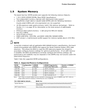
... 128 M x 8/128 M x 8 16 2048 MB SS 4096 MB DS 2 Gbit 2 Gbit 256 M x 8/empty 8 256 M x8/256 M x 8 16 Note: "DS" refers to double-sided memory...2 Gb memory technology). For information about... This allows the BIOS to read the SPD data and program the chipset to ...GB using 512 MB x16 module • Non-ECC DIMMs • Serial Presence Detect • DDR3 1600 MHz, 1333 MHz, and DDR3 1066 MHz SDRAM DIMMs • XMP version 1.2 performance profile support for optimum performance. If non-SPD memory is installed, the BIOS will attempt to : http://support.intel.com/support/motherboards...
... 128 M x 8/128 M x 8 16 2048 MB SS 4096 MB DS 2 Gbit 2 Gbit 256 M x 8/empty 8 256 M x8/256 M x 8 16 Note: "DS" refers to double-sided memory...2 Gb memory technology). For information about... This allows the BIOS to read the SPD data and program the chipset to ...GB using 512 MB x16 module • Non-ECC DIMMs • Serial Presence Detect • DDR3 1600 MHz, 1333 MHz, and DDR3 1066 MHz SDRAM DIMMs • XMP version 1.2 performance profile support for optimum performance. If non-SPD memory is installed, the BIOS will attempt to : http://support.intel.com/support/motherboards...

Product Specification
Page 18
...port • One port used to connect the onboard Bluetooth Module For information about The Intel P55 Express Chipset Resources used by the chipset Refer to http://www.intel.com/products/desktop/chipsets/index.htm Chapter 2 1.6.1 USB The board supports up to fourteen USB 2.0 ports, ...the processor and the USB, SATA, LPC, LAN, PCI, and PCIe interfaces. Intel Desktop Board DP55KG Technical Product Specification 1.6 Intel® P55 Express Chipset The Intel P55 Express Chipset consisting of the Intel P55 Platform Controller Hub (PCH) provides interfaces to Figure 10, page 42 Figure 11...
...port • One port used to connect the onboard Bluetooth Module For information about The Intel P55 Express Chipset Resources used by the chipset Refer to http://www.intel.com/products/desktop/chipsets/index.htm Chapter 2 1.6.1 USB The board supports up to fourteen USB 2.0 ports, ...the processor and the USB, SATA, LPC, LAN, PCI, and PCIe interfaces. Intel Desktop Board DP55KG Technical Product Specification 1.6 Intel® P55 Express Chipset The Intel P55 Express Chipset consisting of the Intel P55 Platform Controller Hub (PCH) provides interfaces to Figure 10, page 42 Figure 11...

Product Specification
Page 28
Thermal Sensors and Fan Headers 28 Intel Desktop Board DP55KG Technical Product Specification 1.13.4 Thermal Monitoring Figure 6 shows the locations of the thermal sensors and fan headers. Item A B C D E F G Description Rear chassis fan header Voltage regulator thermal diode Processor fan header Thermal diode, located on processor die Front chassis fan header Thermal diode, located on the Intel P55 Express Chipset Auxiliary fan header Figure 6.
Thermal Sensors and Fan Headers 28 Intel Desktop Board DP55KG Technical Product Specification 1.13.4 Thermal Monitoring Figure 6 shows the locations of the thermal sensors and fan headers. Item A B C D E F G Description Rear chassis fan header Voltage regulator thermal diode Processor fan header Thermal diode, located on processor die Front chassis fan header Thermal diode, located on the Intel P55 Express Chipset Auxiliary fan header Figure 6.

Product Specification
Page 39
...PCI Express add-in cards, PCI Express configuration space, BIOS (SPI Flash device), and chipset overhead resides above the 4 GB boundary. These functions include the following: • BIOS/SPI Flash device (16 Mbit) • Local APIC (19 MB) • Direct Media Interface (40 MB... On a system that is no overlap of DRAM (total system memory). 2 Technical Reference 2.1 Memory Resources 2.1.1 Addressable Memory The board utilizes 16 GB of the system memory map. All installed system memory can be used when there is dynamically allocated for other system critical functions. Figure 9...
...PCI Express add-in cards, PCI Express configuration space, BIOS (SPI Flash device), and chipset overhead resides above the 4 GB boundary. These functions include the following: • BIOS/SPI Flash device (16 Mbit) • Local APIC (19 MB) • Direct Media Interface (40 MB... On a system that is no overlap of DRAM (total system memory). 2 Technical Reference 2.1 Memory Resources 2.1.1 Addressable Memory The board utilizes 16 GB of the system memory map. All installed system memory can be used when there is dynamically allocated for other system critical functions. Figure 9...

Product Specification
Page 59
... temperatures for Components Component Maximum Case Temperature Processor For processor case temperature, see processor datasheets and processor specification updates Intel P55 Express Chipset 111 oC (under bias) For information about Processor datasheets and specification updates Refer to thermal changes. Thermal Considerations ...or operating frequency could affect case temperatures. Technical Reference Item A B C Description Processor voltage regulator area Processor Intel P55 Express Chipset Figure 17. Maximum case temperatures are sensitive to Section 1.3, page 14 59
... temperatures for Components Component Maximum Case Temperature Processor For processor case temperature, see processor datasheets and processor specification updates Intel P55 Express Chipset 111 oC (under bias) For information about Processor datasheets and specification updates Refer to thermal changes. Thermal Considerations ...or operating frequency could affect case temperatures. Technical Reference Item A B C Description Processor voltage regulator area Processor Intel P55 Express Chipset Figure 17. Maximum case temperatures are sensitive to Section 1.3, page 14 59

Product Specification
Page 62
Intel Desktop Board DP55KG Technical Product Specification Table 25 lists the BIOS Setup program menu features. BIOS Setup Program Menu Bar Maintenance Main Advanced Performance Security Clears passwords and displays processor information Displays processor and memory configuration Configures advanced features available through the chipset...Exits the menu 3.2 BIOS Flash Memory Organization The Serial Peripheral Interface Flash Memory (SPI Flash) includes a 16 Mbit (2048 KB) flash memory device. 3.3 Resource Configuration 3.3.1 PCI Autoconfiguration The BIOS can automatically configure PCI...
Intel Desktop Board DP55KG Technical Product Specification Table 25 lists the BIOS Setup program menu features. BIOS Setup Program Menu Bar Maintenance Main Advanced Performance Security Clears passwords and displays processor information Displays processor and memory configuration Configures advanced features available through the chipset...Exits the menu 3.2 BIOS Flash Memory Organization The Serial Peripheral Interface Flash Memory (SPI Flash) includes a 16 Mbit (2048 KB) flash memory device. 3.3 Resource Configuration 3.3.1 PCI Autoconfiguration The BIOS can automatically configure PCI...

Product Specification
Page 73
... information about the POST codes generated by any PEIM/driver for debug. 10 - 1F Host Processors: 1F is an unrecoverable CPU error. 20 - 2F Memory/Chipset: 2F is no memory detected or no useful memory detected. 30 - 3F Recovery: 3F indicated recovery failure. 40 - 4F Reserved for new busses). Output Devices...
... information about the POST codes generated by any PEIM/driver for debug. 10 - 1F Host Processors: 1F is an unrecoverable CPU error. 20 - 2F Memory/Chipset: 2F is no memory detected or no useful memory detected. 30 - 3F Recovery: 3F indicated recovery failure. 40 - 4F Reserved for new busses). Output Devices...

Product Specification
Page 74
... the host processor (Boot Strap Processor) 11 Host processor cache initialization (including APs) 12 Starting Application processor initialization 13 SMM initialization Chipset 21 Initializing a chipset component Memory 22 Reading SPD from memory DIMMs 23 Detecting presence of memory DIMMs 24 Programming timing parameters in the memory controller and ... VGA controller Remote Console 78 Resetting the console controller 79 Disabling the console controller 7A Enabling the console controller continued 74 Intel Desktop Board DP55KG Technical Product Specification Table 34.
... the host processor (Boot Strap Processor) 11 Host processor cache initialization (including APs) 12 Starting Application processor initialization 13 SMM initialization Chipset 21 Initializing a chipset component Memory 22 Reading SPD from memory DIMMs 23 Detecting presence of memory DIMMs 24 Programming timing parameters in the memory controller and ... VGA controller Remote Console 78 Resetting the console controller 79 Disabling the console controller 7A Enabling the console controller continued 74 Intel Desktop Board DP55KG Technical Product Specification Table 34.

Product Specification
Page 77
Typical Port 80h POST Sequence POST Code Description 21 Initializing a chipset component 22 Reading SPD from memory DIMMs 23 Detecting presence of memory DIMMs 25 Configuring memory 28 Testing memory 34 Loading recovery capsule E4 Entered ...
Typical Port 80h POST Sequence POST Code Description 21 Initializing a chipset component 22 Reading SPD from memory DIMMs 23 Detecting presence of memory DIMMs 25 Configuring memory 28 Testing memory 34 Loading recovery capsule E4 Entered ...
