
Product Specification
Page 6
... BIOS Updates 64 3.6.1 Language Support 64 3.6.2 Custom Splash Screen 65 3.7 BIOS Recovery 65 3.8 Boot Options 66 3.8.1 Optical Drive Boot 66 3.8.2 Network Boot 66 3.8.3 Booting Without Attached Devices 66 3.8.4 Changing the Default Boot Device During POST 66 3.9 Adjusting Boot Speed 67 3.9.1 Peripheral Selection and Configuration 67 3.9.2 BIOS Boot Optimizations 67 3.10 BIOS Security Features 68 3.11 BIOS Performance Features 69 4 Error Messages and Beep Codes 4.1 Speaker 71 4.2 BIOS Beep Codes 71 4.3 Front-panel Power LED Blink Codes 72 4.4 BIOS Error Messages 72 4.5 Port...
... BIOS Updates 64 3.6.1 Language Support 64 3.6.2 Custom Splash Screen 65 3.7 BIOS Recovery 65 3.8 Boot Options 66 3.8.1 Optical Drive Boot 66 3.8.2 Network Boot 66 3.8.3 Booting Without Attached Devices 66 3.8.4 Changing the Default Boot Device During POST 66 3.9 Adjusting Boot Speed 67 3.9.1 Peripheral Selection and Configuration 67 3.9.2 BIOS Boot Optimizations 67 3.10 BIOS Security Features 68 3.11 BIOS Performance Features 69 4 Error Messages and Beep Codes 4.1 Speaker 71 4.2 BIOS Beep Codes 71 4.3 Front-panel Power LED Blink Codes 72 4.4 BIOS Error Messages 72 4.5 Port...

Product Specification
Page 7
... Figure 11 44 10. Supported Memory Configurations 15 4. Processor Core Power Connector 48 vii LAN Connector LED Locations 25 6. Feature Summary 9 2. LAN Connector LED States 25 5. Thermal Sensors and Fan Headers 28 7. Connection Diagram for IEEE 1394a Header 52 15. Locations of the Jumper Block 53 16. Board Dimensions 55 17. Front Panel Audio Header 45 11. SATA Connectors 45 12. Detailed System Memory Address Map 40 10. Localized High Temperature Zones 59 Tables 1. Component-side Connectors and Headers Shown in Figure 1 12...
... Figure 11 44 10. Supported Memory Configurations 15 4. Processor Core Power Connector 48 vii LAN Connector LED Locations 25 6. Feature Summary 9 2. LAN Connector LED States 25 5. Thermal Sensors and Fan Headers 28 7. Connection Diagram for IEEE 1394a Header 52 15. Locations of the Jumper Block 53 16. Board Dimensions 55 17. Front Panel Audio Header 45 11. SATA Connectors 45 12. Detailed System Memory Address Map 40 10. Localized High Temperature Zones 59 Tables 1. Component-side Connectors and Headers Shown in Figure 1 12...

Product Specification
Page 8
.... Acceptable Drives/Media Types for a One-Color Power LED 51 19. Port 80h POST Code Ranges 73 34. States for BIOS Recovery 65 28. BIOS Setup Program Function Keys 62 27. Lead-Free Board Markings 84 38. Front Panel Header 50 18. Environmental Specifications 60 25. Front-panel Power LED Blink Codes 72 32. BIOS Setup Configuration Jumper Settings 54 21. Boot Device Menu Options 66 29. BIOS Beep Codes 71 31. Port 80h POST Codes 74 35. Typical Port 80h POST Sequence 77 36. Main Power Connector 49 17. Intel Desktop Board DP55KG...
.... Acceptable Drives/Media Types for a One-Color Power LED 51 19. Port 80h POST Code Ranges 73 34. States for BIOS Recovery 65 28. BIOS Setup Program Function Keys 62 27. Lead-Free Board Markings 84 38. Front Panel Header 50 18. Environmental Specifications 60 25. Front-panel Power LED Blink Codes 72 32. BIOS Setup Configuration Jumper Settings 54 21. Boot Device Menu Options 66 29. BIOS Beep Codes 71 31. Port 80h POST Codes 74 35. Typical Port 80h POST Sequence 77 36. Main Power Connector 49 17. Intel Desktop Board DP55KG...

Product Specification
Page 9
... in x8 mode when second slot is populated) ― 1 x8 PCIe 2.0 Graphics interface ― Two DDR3 memory channels • Four 240-pin DDR3 SDRAM Dual Inline Memory Module (DIMM) sockets • Support for DDR3 1600 MHz, DDR3 1333 MHz, and DDR3 1066 MHz DIMMs • Support for 1 Gb and 2 Gb memory technology • Support for up to connect the onboard Bluetooth* Module • Eight internal Serial ATA (SATA) 3.0 Gb/s interfaces: ― Six interfaces through Intel P55 PCH with RAID support (black...
... in x8 mode when second slot is populated) ― 1 x8 PCIe 2.0 Graphics interface ― Two DDR3 memory channels • Four 240-pin DDR3 SDRAM Dual Inline Memory Module (DIMM) sockets • Support for DDR3 1600 MHz, DDR3 1333 MHz, and DDR3 1066 MHz DIMMs • Support for 1 Gb and 2 Gb memory technology • Support for up to connect the onboard Bluetooth* Module • Eight internal Serial ATA (SATA) 3.0 Gb/s interfaces: ― Six interfaces through Intel P55 PCH with RAID support (black...

Product Specification
Page 12
...panel audio header F S/PDIF out header G PCI Express x1 bus add-in card connector H Rear chassis fan header I PCI Express x1 bus add-in card connector J PCI Express x16 bus add-in card connector K Battery L Back panel connectors M Vertical USB connector N Processor core power connector (2 X 4) O Processor fan header P Processor LED (red) Q Voltage Regulator LED (red) R LGA1156 processor socket S Post Code LED Display T DIMM Channel A sockets (2) U DIMM Channel B sockets (2) V Onboard power button W Standby power indicator LED (green) X Main power connector...
...panel audio header F S/PDIF out header G PCI Express x1 bus add-in card connector H Rear chassis fan header I PCI Express x1 bus add-in card connector J PCI Express x16 bus add-in card connector K Battery L Back panel connectors M Vertical USB connector N Processor core power connector (2 X 4) O Processor fan header P Processor LED (red) Q Voltage Regulator LED (red) R LGA1156 processor socket S Post Code LED Display T DIMM Channel A sockets (2) U DIMM Channel B sockets (2) V Onboard power button W Standby power indicator LED (green) X Main power connector...

Product Specification
Page 14
... processors Chipset information BIOS and driver updates Tested memory Integration information Visit this board. 14 Supported processors Refer to ) the following: • No parallel port connector • No floppy drive connector • No serial port connector or header • No PS/2 connectors 1.3 Online Support To find information about ... Intel Desktop Board DP55KG Technical Product Specification 1.2 Legacy Considerations This board differs from other Intel Desktop Board products, with margin to support the Intel Core i7 and Intel Core i5 processors in an LGA1156 socket...
... processors Chipset information BIOS and driver updates Tested memory Integration information Visit this board. 14 Supported processors Refer to ) the following: • No parallel port connector • No floppy drive connector • No serial port connector or header • No PS/2 connectors 1.3 Online Support To find information about ... Intel Desktop Board DP55KG Technical Product Specification 1.2 Legacy Considerations This board differs from other Intel Desktop Board products, with margin to support the Intel Core i7 and Intel Core i5 processors in an LGA1156 socket...
Product Specification
Page 15
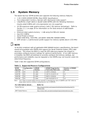
... Serial Presence Detect (SPD) data structure. Tested Memory XMP Tested Memory Refer to accurately configure memory settings for memory speeds above 1333 MHz NOTE To be fully compliant with all applicable DDR SDRAM memory specifications, the board should be impacted or the DIMMs may be populated with 2 Gb memory technology). This allows the BIOS to read the SPD data and program the chipset to : http://support.intel.com/support/motherboards/desktop...
... Serial Presence Detect (SPD) data structure. Tested Memory XMP Tested Memory Refer to accurately configure memory settings for memory speeds above 1333 MHz NOTE To be fully compliant with all applicable DDR SDRAM memory specifications, the board should be impacted or the DIMMs may be populated with 2 Gb memory technology). This allows the BIOS to read the SPD data and program the chipset to : http://support.intel.com/support/motherboards/desktop...
Product Specification
Page 19
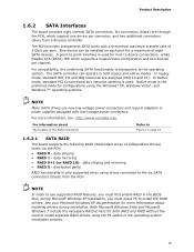
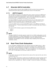
...-voltage power connectors and require adapters or power supplies equipped with a theoretical maximum transfer rate of eight SATA devices. The SATA controller can be installed on each port for a maximum of 3 Gb/s per port. NOTE In order to -point interface is used . For compatibility, the underlying SATA functionality is only supported when using drives connected to device connections, unlike Parallel ATA (PATA) IDE which support one device per channel. data mirroring • RAID 0+1 (or RAID 10) - In legacy mode, standard IDE...
...-voltage power connectors and require adapters or power supplies equipped with a theoretical maximum transfer rate of eight SATA devices. The SATA controller can be installed on each port for a maximum of 3 Gb/s per port. NOTE In order to -point interface is used . For compatibility, the underlying SATA functionality is only supported when using drives connected to device connections, unlike Parallel ATA (PATA) IDE which support one device per channel. data mirroring • RAID 0+1 (or RAID 10) - In legacy mode, standard IDE...
Product Specification
Page 20
... as RAID configurations. When the computer is accurate to the six SATA connectors of the PCH SATA interface. Replace the battery with a theoretical maximum transfer rate of multiple hard drives on the back panel can be accurate. The Marvell 88E6145 controller uses the PCI Express bus for example, the date and time) might not be used for more information about installing drivers during POST. To use the eSATA ports you must enable RAID support...
... as RAID configurations. When the computer is accurate to the six SATA connectors of the PCH SATA interface. Replace the battery with a theoretical maximum transfer rate of multiple hard drives on the back panel can be accurate. The Marvell 88E6145 controller uses the PCI Express bus for example, the date and time) might not be used for more information about installing drivers during POST. To use the eSATA ports you must enable RAID support...
Product Specification
Page 24
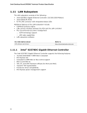
Intel Desktop Board DP55KG Technical Product Specification 1.11 LAN Subsystem The LAN subsystem consists of the following: • Intel 82578DC Gigabit Ethernet Controller (10/100/1000 Mbits/s) • Intel 82801IJR (PCH) • RJ-45 LAN connector with integrated status LEDs Additional features of the LAN subsystem include: • CSMA/CD protocol engine • LAN connect interface between the PCH and the LAN controller • PCI Conventional bus power management ⎯ ACPI technology support ⎯...
Intel Desktop Board DP55KG Technical Product Specification 1.11 LAN Subsystem The LAN subsystem consists of the following: • Intel 82578DC Gigabit Ethernet Controller (10/100/1000 Mbits/s) • Intel 82801IJR (PCH) • RJ-45 LAN connector with integrated status LEDs Additional features of the LAN subsystem include: • CSMA/CD protocol engine • LAN connect interface between the PCH and the LAN controller • PCI Conventional bus power management ⎯ ACPI technology support ⎯...

Product Specification
Page 52
... the IEEE 1394a header is a connection diagram for IEEE 1394a Header 52 Connection Diagram for Front Panel USB Headers 2.2.2.6 Front Panel IEEE 1394a Header Figure 14 is fused. • Use only a front panel USB connector that conforms to the USB 2.0 specification for the IEEE 1394a header. Figure 14. Connection Diagram for the front panel USB headers. NOTE • The +12 V DC power on the USB headers is a connection diagram for high-speed USB devices. Figure 13. Intel Desktop Board DP55KG Technical Product Specification 2.2.2.5 Front Panel USB Headers Figure 13...
... the IEEE 1394a header is a connection diagram for IEEE 1394a Header 52 Connection Diagram for Front Panel USB Headers 2.2.2.6 Front Panel IEEE 1394a Header Figure 14 is fused. • Use only a front panel USB connector that conforms to the USB 2.0 specification for the IEEE 1394a header. Figure 14. Connection Diagram for the front panel USB headers. NOTE • The +12 V DC power on the USB headers is a connection diagram for high-speed USB devices. Figure 13. Intel Desktop Board DP55KG Technical Product Specification 2.2.2.5 Front Panel USB Headers Figure 13...
Product Specification
Page 61
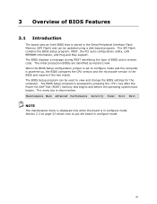
... Flash contains the BIOS Setup program, POST, the PCI auto-configuration utility, LAN EEPROM information, and Plug and Play support. The initial production BIOSs are identified as KGIBX10J.86A. The BIOS Setup program can be used to view and change the BIOS settings for the computer. Maintenance Main Advanced Performance Security Power Boot Exit NOTE The maintenance menu is displayed only when the board is in the Serial Peripheral Interface Flash Memory (SPI Flash) and can be updated using a disk...
... Flash contains the BIOS Setup program, POST, the PCI auto-configuration utility, LAN EEPROM information, and Plug and Play support. The initial production BIOSs are identified as KGIBX10J.86A. The BIOS Setup program can be used to view and change the BIOS settings for the computer. Maintenance Main Advanced Performance Security Power Boot Exit NOTE The maintenance menu is displayed only when the board is in the Serial Peripheral Interface Flash Memory (SPI Flash) and can be updated using a disk...

Product Specification
Page 62
... Flash Memory (SPI Flash) includes a 16 Mbit (2048 KB) flash memory device. 3.3 Resource Configuration 3.3.1 PCI Autoconfiguration The BIOS can automatically configure PCI devices. Any interrupts set to Available in Setup are considered to be onboard or add-in card. 62 Intel Desktop Board DP55KG Technical Product Specification Table 25 lists the BIOS Setup program menu features. Table 26. Table 25. Autoconfiguration lets a user insert or remove PCI cards without having to Setup program options Table 26 lists the function keys available for menu screens. When a user turns...
... Flash Memory (SPI Flash) includes a 16 Mbit (2048 KB) flash memory device. 3.3 Resource Configuration 3.3.1 PCI Autoconfiguration The BIOS can automatically configure PCI devices. Any interrupts set to Available in Setup are considered to be onboard or add-in card. 62 Intel Desktop Board DP55KG Technical Product Specification Table 25 lists the BIOS Setup program menu features. Table 26. Table 25. Autoconfiguration lets a user insert or remove PCI cards without having to Setup program options Table 26 lists the function keys available for menu screens. When a user turns...

Product Specification
Page 66
... CD-ROM format specification. Boot devices are not present: • Video adapter • Keyboard • Mouse 3.8.4 Changing the Default Boot Device During POST Pressing the key during POST automatically forces booting from the onboard LAN or a network add-in the BIOS setup program's Boot Device Priority Submenu). Pressing the key during POST causes a boot device menu to Full. 3.8.3 Booting Without Attached Devices For use this key during POST, the User Access Level in the BIOS Setup program's Security menu must be displayed. This selection allows booting from the LAN...
... CD-ROM format specification. Boot devices are not present: • Video adapter • Keyboard • Mouse 3.8.4 Changing the Default Boot Device During POST Pressing the key during POST automatically forces booting from the onboard LAN or a network add-in the BIOS setup program's Boot Device Priority Submenu). Pressing the key during POST causes a boot device menu to Full. 3.8.3 Booting Without Attached Devices For use this key during POST, the User Access Level in the BIOS Setup program's Security menu must be displayed. This selection allows booting from the LAN...
Product Specification
Page 68
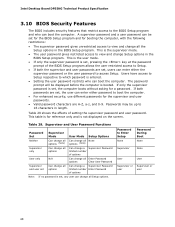
... password is set for the BIOS Setup program and for a password. Intel Desktop Board DP55KG Technical Product Specification 3.10 BIOS Security Features The BIOS includes security features that restrict access to the BIOS Setup program and who can boot the computer. A supervisor password and a user password can be up to 16 characters in the BIOS Setup program. This is the supervisor mode. • The user password gives restricted access to Enter Setup None Password During Boot None Supervisor None User User...
... password is set for the BIOS Setup program and for a password. Intel Desktop Board DP55KG Technical Product Specification 3.10 BIOS Security Features The BIOS includes security features that restrict access to the BIOS Setup program and who can boot the computer. A supervisor password and a user password can be up to 16 characters in the BIOS Setup program. This is the supervisor mode. • The user password gives restricted access to Enter Setup None Password During Boot None Supervisor None User User...

Product Specification
Page 72
Replace the battery soon. Memory Size Decreased Memory size has decreased since the last boot. BIOS Error Messages Error Message Explanation CMOS Battery Low The battery may have been corrupted. Intel Desktop Board DP55KG Technical Product Specification 4.3 Front-panel Power LED Blink Codes Whenever a recoverable error occurs during POST, the BIOS causes the board's front panel power LED to boot. 72 Front-panel Power LED Blink Codes Type Pattern F2 Setup/F10 Boot Menu None Prompt BIOS update in a total of each ) two times, then 2.5-second pause (off), entire ...
Replace the battery soon. Memory Size Decreased Memory size has decreased since the last boot. BIOS Error Messages Error Message Explanation CMOS Battery Low The battery may have been corrupted. Intel Desktop Board DP55KG Technical Product Specification 4.3 Front-panel Power LED Blink Codes Whenever a recoverable error occurs during POST, the BIOS causes the board's front panel power LED to boot. 72 Front-panel Power LED Blink Codes Type Pattern F2 Setup/F10 Boot Menu None Prompt BIOS update in a total of each ) two times, then 2.5-second pause (off), entire ...

Product Specification
Page 73
... an unrecoverable CPU error. 20 - 2F Memory/Chipset: 2F is no memory detected or no useful memory detected. 30 - 3F Recovery: 3F indicated recovery failure. 40 - 4F Reserved for future use (new output console codes). 90 - 9F Input devices: Keyboard/Mouse. 9F is an unrecoverable error. EF: boot/S3 resume failure. C0 - The POST card can decode the port and display the contents on a medium such as a seven-segment display. Start with PCI. 60...
... an unrecoverable CPU error. 20 - 2F Memory/Chipset: 2F is no memory detected or no useful memory detected. 30 - 3F Recovery: 3F indicated recovery failure. 40 - 4F Reserved for future use (new output console codes). 90 - 9F Input devices: Keyboard/Mouse. 9F is an unrecoverable error. EF: boot/S3 resume failure. C0 - The POST card can decode the port and display the contents on a medium such as a seven-segment display. Start with PCI. 60...

Product Specification
Page 75
... Resetting removable media B9 Disabling removable media BA Detecting presence of a removable media (CD-ROM detection, etc.) BC Enabling/configuring a removable media BDS Dy Trying boot selection y (y=0 to 15) PEI Core E0 Started dispatching PEIMs (emitted on first report of EFI_SW_PC_INIT_BEGIN EFI_SW_PEI_PC_HANDOFF_TO_NEXT) E2 E1, E3 Permanent memory found Reserved for PEI/PEIMs DXE Core E4 Entered DXE phase E5 Started dispatching drivers E6 Started connecting drivers continued 75 Error Messages and Beep Codes...
... Resetting removable media B9 Disabling removable media BA Detecting presence of a removable media (CD-ROM detection, etc.) BC Enabling/configuring a removable media BDS Dy Trying boot selection y (y=0 to 15) PEI Core E0 Started dispatching PEIMs (emitted on first report of EFI_SW_PC_INIT_BEGIN EFI_SW_PEI_PC_HANDOFF_TO_NEXT) E2 E1, E3 Permanent memory found Reserved for PEI/PEIMs DXE Core E4 Entered DXE phase E5 Started dispatching drivers E6 Started connecting drivers continued 75 Error Messages and Beep Codes...
Product Specification
Page 76
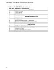
Intel Desktop Board DP55KG Technical Product Specification Table 34. Port 80h POST Codes (continued) POST Code Description of POST Operation DXE Drivers E7 Waiting for user input E8 Checking password E9 Entering BIOS setup EB Calling Legacy Option ROMs Runtime Phase/EFI OS Boot F4 Entering Sleep state F5 Exiting Sleep state F8 EFI boot service ExitBootServices ( ) has been called F9 EFI runtime service SetVirtualAddressMap ( ) has been called FA EFI runtime service ResetSystem ( ) has been called PEIMs/Recovery 30...
Intel Desktop Board DP55KG Technical Product Specification Table 34. Port 80h POST Codes (continued) POST Code Description of POST Operation DXE Drivers E7 Waiting for user input E8 Checking password E9 Entering BIOS setup EB Calling Legacy Option ROMs Runtime Phase/EFI OS Boot F4 Entering Sleep state F5 Exiting Sleep state F8 EFI boot service ExitBootServices ( ) has been called F9 EFI runtime service SetVirtualAddressMap ( ) has been called FA EFI runtime service ResetSystem ( ) has been called PEIMs/Recovery 30...

Product Specification
Page 77
Error Messages and Beep Codes Table 35. Typical Port 80h POST Sequence POST Code Description 21 Initializing a chipset component 22 Reading SPD from memory DIMMs 23 Detecting presence of memory DIMMs 25 Configuring memory 28 Testing memory 34 Loading recovery capsule E4 Entered DXE phase 12 Starting application processor initialization 13 SMM initialization 50 Enumerating PCI busses 51 Allocating resourced to PCI bus 92 Detecting the presence of the keyboard 90 Resetting keyboard 94 Clearing keyboard input...
Error Messages and Beep Codes Table 35. Typical Port 80h POST Sequence POST Code Description 21 Initializing a chipset component 22 Reading SPD from memory DIMMs 23 Detecting presence of memory DIMMs 25 Configuring memory 28 Testing memory 34 Loading recovery capsule E4 Entered DXE phase 12 Starting application processor initialization 13 SMM initialization 50 Enumerating PCI busses 51 Allocating resourced to PCI bus 92 Detecting the presence of the keyboard 90 Resetting keyboard 94 Clearing keyboard input...


