Product Guide
Page 3
... as Information Technology Equipment (I.T.E.) for use in personal computers (PC) for installation in this product for technically qualified personnel. The suitability of product features 2 Installing and Replacing Desktop Board Components: instructions on how to install the Desktop Board and other environments, such as follows: 1 Desktop Board Features: a summary of this manual: CAUTION Cautions warn the user about board layout, component installation, BIOS update, and regulatory requirements for Intel® Desktop Board DG45ID. Document...
... as Information Technology Equipment (I.T.E.) for use in personal computers (PC) for installation in this product for technically qualified personnel. The suitability of product features 2 Installing and Replacing Desktop Board Components: instructions on how to install the Desktop Board and other environments, such as follows: 1 Desktop Board Features: a summary of this manual: CAUTION Cautions warn the user about board layout, component installation, BIOS update, and regulatory requirements for Intel® Desktop Board DG45ID. Document...

Product Guide
Page 5
...DVI-I Support 15 HDMI* Technology Support 15 PCI Express x16 Graphics 16 Intel® Viiv™ Technology 16 Audio Subsystem 16 Legacy Input/Output (I/O) Controller 17 LAN Subsystem 17 LAN Subsystem Software 17 LAN Status Indicators 18 Hi-Speed USB 2.0 Support 18 Serial ATA...19 Serial ATA RAID 19 Intel® Rapid Recover Technology (Intel® RRT 19 Expandability...19 BIOS ...20 Serial ATA Auto Configuration 20 PCI and PCI Express* Auto Configuration 20 Security Passwords 20 Hardware Management Features 21 Fan Speed, Thermal, and Voltage Monitoring and Control 21 Chassis...
...DVI-I Support 15 HDMI* Technology Support 15 PCI Express x16 Graphics 16 Intel® Viiv™ Technology 16 Audio Subsystem 16 Legacy Input/Output (I/O) Controller 17 LAN Subsystem 17 LAN Subsystem Software 17 LAN Status Indicators 18 Hi-Speed USB 2.0 Support 18 Serial ATA...19 Serial ATA RAID 19 Intel® Rapid Recover Technology (Intel® RRT 19 Expandability...19 BIOS ...20 Serial ATA Auto Configuration 20 PCI and PCI Express* Auto Configuration 20 Security Passwords 20 Hardware Management Features 21 Fan Speed, Thermal, and Voltage Monitoring and Control 21 Chassis...
Product Guide
Page 6
...CIR) Headers 46 Serial Port Header 47 Chassis Intrusion Header 47 Alternate Front Panel Power LED Header 47 Front Panel Header 48 USB 2.0 Headers 48 IEEE 1394a Header 49 Connecting to the Audio System 49 Connecting Chassis Fan and Power Supply Cables 50 Chassis Fan Cables 50 Power Supply Cables 51 Setting the BIOS Configuration Jumper 52 Clearing Passwords 53 3 Updating the BIOS 61 Updating the BIOS with the Intel® Express BIOS Update Utility 61 Updating the BIOS with the ISO Image BIOS Update File or the Iflash Memory Update Utility ...62 Obtaining the BIOS Update File 62...
...CIR) Headers 46 Serial Port Header 47 Chassis Intrusion Header 47 Alternate Front Panel Power LED Header 47 Front Panel Header 48 USB 2.0 Headers 48 IEEE 1394a Header 49 Connecting to the Audio System 49 Connecting Chassis Fan and Power Supply Cables 50 Chassis Fan Cables 50 Power Supply Cables 51 Setting the BIOS Configuration Jumper 52 Clearing Passwords 53 3 Updating the BIOS 61 Updating the BIOS with the Intel® Express BIOS Update Utility 61 Updating the BIOS with the ISO Image BIOS Update File or the Iflash Memory Update Utility ...62 Obtaining the BIOS Update File 62...
Product Guide
Page 7
...65 Configuring the BIOS for Intel Matrix Storage Technology 65 Creating Your RAID Set 65 Loading the Intel Matrix Storage Technology RAID Drivers and Software 66 Setting Up a "RAID Ready" System 66 5 Configuring for Intel® Rapid Recover Technology 67 Enabling Intel Rapid Recover Technology 67 Creating a Recovery Volume 68 Creating a Recovery Volume Using the RAID Option ROM 68 Creating a Recovery Volume Using the Intel Matrix Storage Console 68 Disk Synchronization Mode 69 Mounting the Recovery Disk 69 A Error Messages and Indicators 71 BIOS Beep Codes 71 BIOS Error Messages...
...65 Configuring the BIOS for Intel Matrix Storage Technology 65 Creating Your RAID Set 65 Loading the Intel Matrix Storage Technology RAID Drivers and Software 66 Setting Up a "RAID Ready" System 66 5 Configuring for Intel® Rapid Recover Technology 67 Enabling Intel Rapid Recover Technology 67 Creating a Recovery Volume 68 Creating a Recovery Volume Using the RAID Option ROM 68 Creating a Recovery Volume Using the Intel Matrix Storage Console 68 Disk Synchronization Mode 69 Mounting the Recovery Disk 69 A Error Messages and Indicators 71 BIOS Beep Codes 71 BIOS Error Messages...
Product Guide
Page 8
... 21. Location of the Chassis Fan Headers 50 24. Installing a DIMM 39 18. Connecting Power Supply Cables 51 25. China RoHS Environmentally Friendly Use Period Mark 80 22. Internal Headers and Connectors 44 22. S/PDIF Connector Signal Names 45 7. Safety Standards 73 20. Use DDR2 DIMMs 38 17. Location of the BIOS Configuration Jumper Block 52 26. HD Audio Link Header Signal Names 45 6. Removing a PCI Express x16 Card 42 20. USB 2.0 Header Signal Names 48 15. Desktop Board DG45ID...
... 21. Location of the Chassis Fan Headers 50 24. Installing a DIMM 39 18. Connecting Power Supply Cables 51 25. China RoHS Environmentally Friendly Use Period Mark 80 22. Internal Headers and Connectors 44 22. S/PDIF Connector Signal Names 45 7. Safety Standards 73 20. Use DDR2 DIMMs 38 17. Location of the BIOS Configuration Jumper Block 52 26. HD Audio Link Header Signal Names 45 6. Removing a PCI Express x16 Card 42 20. USB 2.0 Header Signal Names 48 15. Desktop Board DG45ID...

Product Guide
Page 9
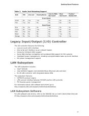
...processor in cards • High-Definition Multimedia Interface* (HDMI*) output • Support for dual independent displays via the HDMI/DVI-I ports Onboard subsystem, featuring: • Independent 8-channel (7.1) audio streams • 2-channel stereo audio streams via an onboard header • Intel® High Definition Audio (Intel® HD Audio) interface • IDT* 92HD73E audio codec • Back panel optical S/PDIF output connector and an onboard 3-pin S/PDIF output connector • Dolby Home Theater* certified audio Expansion Capabilities Legacy I/O Support • One PCI...
...processor in cards • High-Definition Multimedia Interface* (HDMI*) output • Support for dual independent displays via the HDMI/DVI-I ports Onboard subsystem, featuring: • Independent 8-channel (7.1) audio streams • 2-channel stereo audio streams via an onboard header • Intel® High Definition Audio (Intel® HD Audio) interface • IDT* 92HD73E audio codec • Back panel optical S/PDIF output connector and an onboard 3-pin S/PDIF output connector • Dolby Home Theater* certified audio Expansion Capabilities Legacy I/O Support • One PCI...

Product Guide
Page 10
... • 32 Mbit symmetrical flash memory device • Support for SMBIOS • Intel® Rapid BIOS Boot • Intel® Express BIOS Update • Support for Advanced Configuration and Power Interface (ACPI) • Suspend to RAM (STR) • Wake on USB, PCI Express, LAN, front panel, and Consumer IR • ENERGY STAR* capable Hardware monitor with: • Three fan sensing inputs used to monitor fan activity • Intel® Quiet System Technology (Intel® QST) fan speed control • Voltage sensing to detect out...
... • 32 Mbit symmetrical flash memory device • Support for SMBIOS • Intel® Rapid BIOS Boot • Intel® Express BIOS Update • Support for Advanced Configuration and Power Interface (ACPI) • Suspend to RAM (STR) • Wake on USB, PCI Express, LAN, front panel, and Consumer IR • ENERGY STAR* capable Hardware monitor with: • Three fan sensing inputs used to monitor fan activity • Intel® Quiet System Technology (Intel® QST) fan speed control • Voltage sensing to detect out...
Product Guide
Page 12
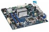
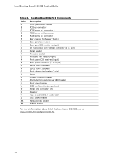
...(3-pin) Back panel connectors Back panel CIR emitter (output) 12 V processor core voltage connector (2 x 2 pin) Serial header Processor socket Processor fan header (4-pin) Front panel CIR receiver (input) Main power connector (2 x 12 pin) DDR2 DIMM 0 sockets DDR2 DIMM 1 sockets Front chassis fan header (3-pin) Battery Chassis intrusion header Alternate front panel power LED header Front panel header BIOS configuration jumper block Serial ATA connectors (5) Speaker High-speed USB 2.0 headers (3) IEEE 1394a header HD audio link header S/PDIF header For more information about Intel Desktop Board...
...(3-pin) Back panel connectors Back panel CIR emitter (output) 12 V processor core voltage connector (2 x 2 pin) Serial header Processor socket Processor fan header (4-pin) Front panel CIR receiver (input) Main power connector (2 x 12 pin) DDR2 DIMM 0 sockets DDR2 DIMM 1 sockets Front chassis fan header (3-pin) Battery Chassis intrusion header Alternate front panel power LED header Front panel header BIOS configuration jumper block Serial ATA connectors (5) Speaker High-speed USB 2.0 headers (3) IEEE 1394a header HD audio link header S/PDIF header For more information about Intel Desktop Board...
Product Guide
Page 13
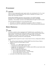
... Desktop Board supports the dual or single channel memory configurations defined below : • Up to 2.0 GB utilizing 256 Mb technology • Up to 4.0 GB utilizing 512 Mb or 1 Gb technology • Up to 8.0 GB utilizing 1 Gb technology • A minimum of 512 MB of total memory is required 13 Desktop Board Features Processor CAUTION Failure to use an appropriate power supply and/or not connecting the 12 V (2 x 2 pin) power connector to the Desktop Board may not function properly. Desktop Board DG45ID supports an Intel processor in...
... Desktop Board supports the dual or single channel memory configurations defined below : • Up to 2.0 GB utilizing 256 Mb technology • Up to 4.0 GB utilizing 512 Mb or 1 Gb technology • Up to 8.0 GB utilizing 1 Gb technology • A minimum of 512 MB of total memory is required 13 Desktop Board Features Processor CAUTION Failure to use an appropriate power supply and/or not connecting the 12 V (2 x 2 pin) power connector to the Desktop Board may not function properly. Desktop Board DG45ID supports an Intel processor in...
Product Guide
Page 14
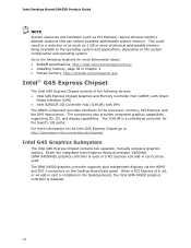
... devices: • Intel G45 Express Chipset Graphics and Memory Controller Hub (GMCH) with Direct Media Interface (DMI) • Intel 82801JR I/O Controller Hub (ICH10R) with DMI The GMCH component provides interfaces to the following locations for the board's I connectors on the Desktop Board back panel. Go to the processor, memory, PCI Express, and the DMI interconnect. Either the integrated Intel Graphics Media Accelerator X4500HD (GMA X4500HD) graphics controller is disabled. 14 The GMA X4500 graphics controller supports dual independent displays...
... devices: • Intel G45 Express Chipset Graphics and Memory Controller Hub (GMCH) with Direct Media Interface (DMI) • Intel 82801JR I/O Controller Hub (ICH10R) with DMI The GMCH component provides interfaces to the following locations for the board's I connectors on the Desktop Board back panel. Go to the processor, memory, PCI Express, and the DMI interconnect. Either the integrated Intel Graphics Media Accelerator X4500HD (GMA X4500HD) graphics controller is disabled. 14 The GMA X4500 graphics controller supports dual independent displays...
Product Guide
Page 17
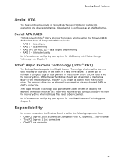
... wake up event interface • PCI power management support LAN Subsystem The LAN subsystem includes: • Intel® ICH10R • Intel 82567LF Gigabit (10/100/1000 Mb/s) Ethernet LAN controller • RJ-45 LAN connector with integrated status LEDs The subsystem features: • CSMA/CD protocol engine • LAN connect interface between ICH10R and the LAN controller • PCI Express power management For information about LAN software and drivers go to http://support.intel.com/support/motherboards/desktop LAN Subsystem Software...
... wake up event interface • PCI power management support LAN Subsystem The LAN subsystem includes: • Intel® ICH10R • Intel 82567LF Gigabit (10/100/1000 Mb/s) Ethernet LAN controller • RJ-45 LAN connector with integrated status LEDs The subsystem features: • CSMA/CD protocol engine • LAN connect interface between ICH10R and the LAN controller • PCI Express power management For information about LAN software and drivers go to http://support.intel.com/support/motherboards/desktop LAN Subsystem Software...
Product Guide
Page 19
... eSATA channel. Intel® Rapid Recover Technology (Intel® RRT) The Desktop Board supports Intel Rapid Recover Technology which enables the following expansion slots: • One PCI Express 2.0 x16 connector (compatible with PCI Express 1.1 add-in the event of your system for RAID using Intel Matrix Storage Technology see Chapter 5. If the master hard drive should fail, either from a mechanical failure or the result of allowing the recovery drive to be mounted as booting from the recovery drive when individual files...
... eSATA channel. Intel® Rapid Recover Technology (Intel® RRT) The Desktop Board supports Intel Rapid Recover Technology which enables the following expansion slots: • One PCI Express 2.0 x16 connector (compatible with PCI Express 1.1 add-in the event of your system for RAID using Intel Matrix Storage Technology see Chapter 5. If the master hard drive should fail, either from a mechanical failure or the result of allowing the recovery drive to be mounted as booting from the recovery drive when individual files...
Product Guide
Page 20
... Intel Desktop Board DG45ID Product Guide BIOS The BIOS provides the Power-On Self-Test (POST), the BIOS Setup program, the PCI/PCI Express auto-configuration utilities, and the video BIOS. If only the supervisor password is booted. If both the supervisor and user passwords are set, you install a PCI/PCI Express add-in card in your computer, the PCI/PCI Express auto-configuration utility in the BIOS automatically detects and configures the resources (IRQs, DMA channels, and I/O space) for that restrict whether the BIOS Setup program can enter either...
... Intel Desktop Board DG45ID Product Guide BIOS The BIOS provides the Power-On Self-Test (POST), the BIOS Setup program, the PCI/PCI Express auto-configuration utilities, and the video BIOS. If only the supervisor password is booted. If both the supervisor and user passwords are set, you install a PCI/PCI Express add-in card in your computer, the PCI/PCI Express auto-configuration utility in the BIOS automatically detects and configures the resources (IRQs, DMA channels, and I/O space) for that restrict whether the BIOS Setup program can enter either...
Product Guide
Page 22
... technology (Suspend to RAM) ⎯ +5 V standby power indicator LED ⎯ Wake from USB ⎯ Power Management Event signal (PME#) wakeup support ⎯ WAKE# signal wake-up support ⎯ Wake from an AC power failure, the computer returns to the power state it was in the BIOS Setup program's Boot menu. The use of the power connectors. 22 When an ACPI-enabled computer receives the correct command, the power supply removes all non-standby voltages. Intel Desktop Board DG45ID Product Guide Power Management Features Power...
... technology (Suspend to RAM) ⎯ +5 V standby power indicator LED ⎯ Wake from USB ⎯ Power Management Event signal (PME#) wakeup support ⎯ WAKE# signal wake-up support ⎯ Wake from an AC power failure, the computer returns to the power state it was in the BIOS Setup program's Boot menu. The use of the power connectors. 22 When an ACPI-enabled computer receives the correct command, the power supply removes all non-standby voltages. Intel Desktop Board DG45ID Product Guide Power Management Features Power...

Product Guide
Page 23
... power supply capacity, the Desktop Board may lose register settings stored in the S3 sleep state, the computer will appear to support the standard Instantly Available (ACPI S3 sleep state) configuration. If the computer has a dual-colored power LED on when the computer is in the ACPI S0 state. • The fans are off . The Desktop Board has a 4-pin processor fan header and two 3-pin chassis fan headers. The Desktop Board supports the PCI Bus Power Management Interface Specification. LAN Wake Capabilities CAUTION For LAN wake...
... power supply capacity, the Desktop Board may lose register settings stored in the S3 sleep state, the computer will appear to support the standard Instantly Available (ACPI S3 sleep state) configuration. If the computer has a dual-colored power LED on when the computer is in the ACPI S0 state. • The fans are off . The Desktop Board has a 4-pin processor fan header and two 3-pin chassis fan headers. The Desktop Board supports the PCI Bus Power Management Interface Specification. LAN Wake Capabilities CAUTION For LAN wake...

Product Guide
Page 27
... • Install and remove the Desktop Board • Install and remove a processor • Install and remove memory • Install and remove a PCI Express x16 card • Connect the Serial ATA cables • Connect to the internal headers • Connect to the onboard audio system • Connect chassis fan and power supply cables • Set the BIOS configuration jumper • Clear passwords • Replace the battery Before You Begin CAUTIONS The procedures in this chapter. Some circuitry on the board can continue to operate even though the front panel power button is...
... • Install and remove the Desktop Board • Install and remove a processor • Install and remove memory • Install and remove a PCI Express x16 card • Connect the Serial ATA cables • Connect to the internal headers • Connect to the onboard audio system • Connect chassis fan and power supply cables • Set the BIOS configuration jumper • Clear passwords • Replace the battery Before You Begin CAUTIONS The procedures in this chapter. Some circuitry on the board can continue to operate even though the front panel power button is...
Product Guide
Page 53
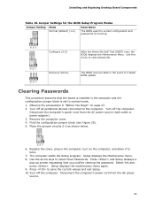
... update. Setup displays the maintenance menu again. 9. Turn off the computer. Disconnect the computer's power cord from the AC power source (wall outlet or power adapter). 3. Remove the computer cover. 4. Find the configuration jumper block (see Figure 25). 5. Select Yes and press . Jumper Settings for the BIOS Setup Program Modes Jumper Setting Mode Normal (default) (1-2) Description The BIOS uses the current configuration and passwords for booting. The computer starts the Setup program. Installing and Replacing Desktop Board Components Table 16. Recovery...
... update. Setup displays the maintenance menu again. 9. Turn off the computer. Disconnect the computer's power cord from the AC power source (wall outlet or power adapter). 3. Remove the computer cover. 4. Find the configuration jumper block (see Figure 25). 5. Select Yes and press . Jumper Settings for the BIOS Setup Program Modes Jumper Setting Mode Normal (default) (1-2) Description The BIOS uses the current configuration and passwords for booting. The computer starts the Setup program. Installing and Replacing Desktop Board Components Table 16. Recovery...
Product Guide
Page 61
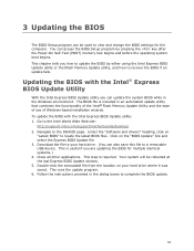
... executable file from the location on your hard drive. (You can update the system BIOS while in the Windows environment. To update the BIOS with the Intel® Express BIOS Update Utility With the Intel Express BIOS Update utility you can also save this file to the Intel World Wide Web site: http://support.intel.com/support/motherboards/desktop/ 2. This step is useful if you how to update the BIOS by pressing the key after the Power-On Self-Test (POST) memory test...
... executable file from the location on your hard drive. (You can update the system BIOS while in the Windows environment. To update the BIOS with the Intel® Express BIOS Update Utility With the Intel Express BIOS Update utility you can also save this file to the Intel World Wide Web site: http://support.intel.com/support/motherboards/desktop/ 2. This step is useful if you how to update the BIOS by pressing the key after the Power-On Self-Test (POST) memory test...

Product Guide
Page 66
... SATA hard drive is added to manage the RAID configuration. Install the Intel® ICH10R SATA RAID Controller driver. Click on the "Load Drivers" option and insert the diskette labeled Intel Matrix Storage Technology RAID Driver (Note: If you do you can be used to the system. Install the Intel Matrix Storage Console software via the Intel Express Installer CD included with your desktop board or after downloading it from http://support.intel.com/support/motherboards/desktop/ to a RAID setup. 66 Intel Desktop Board DG45ID Product Guide Loading the Intel Matrix Storage Technology...
... SATA hard drive is added to manage the RAID configuration. Install the Intel® ICH10R SATA RAID Controller driver. Click on the "Load Drivers" option and insert the diskette labeled Intel Matrix Storage Technology RAID Driver (Note: If you do you can be used to the system. Install the Intel Matrix Storage Console software via the Intel Express Installer CD included with your desktop board or after downloading it from http://support.intel.com/support/motherboards/desktop/ to a RAID setup. 66 Intel Desktop Board DG45ID Product Guide Loading the Intel Matrix Storage Technology...

Product Guide
Page 67
... a designated recovery drive. For the setting Configure SATA as was previously not set to RAID. When using the Update On Request policy, the master drive data can select whether you must span 100 percent of the available hard drive space of an array, and only one recovery volume can be copied to install the Intel Matrix Storage RAID driver during system POST. 2. Enabling Intel Rapid Recover Technology NOTE Intel Rapid Recover Technology does not support RAID...
... a designated recovery drive. For the setting Configure SATA as was previously not set to RAID. When using the Update On Request policy, the master drive data can select whether you must span 100 percent of the available hard drive space of an array, and only one recovery volume can be copied to install the Intel Matrix Storage RAID driver during system POST. 2. Enabling Intel Rapid Recover Technology NOTE Intel Rapid Recover Technology does not support RAID...


