
Product Specification
Page 5
... 1.1 Overview ...10 1.1.1 Feature Summary 10 1.1.2 Manufacturing Options 11 1.1.3 Board Layout 12 1.1.4 Block Diagram 14 1.2 Online Support ...15 1.3 Processor ...15 1.4 System Memory ...16 1.4.1 Memory Configurations 17 1.5 Intel® 945G Chipset ...21 1.5.1 Intel 945G Graphics Subsystem 21 1.5.2 USB ...23 1.5.3 IDE Support 24 1.5.4 ... LAN Subsystem Software 31 1.10.2 10/100 Mbits/sec LAN Subsystem 31 1.10.3 Gigabit LAN Subsystem 32 1.10.4 Intel® Active Management Technology (Optional 33 1.10.5 Alert Standard Format (ASF) Support (Optional 35 1.11 Hardware Management ...
... 1.1 Overview ...10 1.1.1 Feature Summary 10 1.1.2 Manufacturing Options 11 1.1.3 Board Layout 12 1.1.4 Block Diagram 14 1.2 Online Support ...15 1.3 Processor ...15 1.4 System Memory ...16 1.4.1 Memory Configurations 17 1.5 Intel® 945G Chipset ...21 1.5.1 Intel 945G Graphics Subsystem 21 1.5.2 USB ...23 1.5.3 IDE Support 24 1.5.4 ... LAN Subsystem Software 31 1.10.2 10/100 Mbits/sec LAN Subsystem 31 1.10.3 Gigabit LAN Subsystem 32 1.10.4 Intel® Active Management Technology (Optional 33 1.10.5 Alert Standard Format (ASF) Support (Optional 35 1.11 Hardware Management ...

Product Specification
Page 7
...the Jumper Block 65 25. Connection Diagram for Boards with the 8-Channel (7.1) Audio Subsystem 67 27. I /O Shield Dimensions for 6-Channel (5.1) Audio Subsystem .... 30 12. 6-Channel (5.1) Audio Subsystem Block Diagram 30 13. Processor Heatsink for IEEE 1394a Connectors 64 24. ....... 29 10. 8-channel (7.1) Audio Subsystem Block Diagram 29 11. Dual Channel (Interleaved) Mode Configuration with Four DIMMs 19 7. Board Dimensions...66 26. Dual Channel (Interleaved) Mode Configuration with Three DIMMs 18 6. Back Panel Connectors for 6-Channel (5.1) Audio Subsystem 55...
...the Jumper Block 65 25. Connection Diagram for Boards with the 8-Channel (7.1) Audio Subsystem 67 27. I /O Shield Dimensions for 6-Channel (5.1) Audio Subsystem .... 30 12. 6-Channel (5.1) Audio Subsystem Block Diagram 30 13. Processor Heatsink for IEEE 1394a Connectors 64 24. ....... 29 10. 8-channel (7.1) Audio Subsystem Block Diagram 29 11. Dual Channel (Interleaved) Mode Configuration with Four DIMMs 19 7. Board Dimensions...66 26. Dual Channel (Interleaved) Mode Configuration with Three DIMMs 18 6. Back Panel Connectors for 6-Channel (5.1) Audio Subsystem 55...
Product Specification
Page 8
...Two-Color Power LED 63 31. Environmental Specifications 74 36. Power States and Targeted System Power 39 9. I/O Map ...48 13. Processor Fan Connector 59 24. Fan Connector Current Capability 70 34. BIOS Setup Program Function Keys 80 41. Feature Summary ...10 2. Manufacturing ... Power Connector 60 26. Boot Device Menu Options 83 42. Port 80h POST Codes 89 47. Intel Desktop Board D945GTP Technical Product Specification Tables 1. Interrupts ...50 15. Board Components Shown in Figure 20 57 19. BIOS Error Messages 87 45. LAN Connector LED States 32...
...Two-Color Power LED 63 31. Environmental Specifications 74 36. Power States and Targeted System Power 39 9. I/O Map ...48 13. Processor Fan Connector 59 24. Fan Connector Current Capability 70 34. BIOS Setup Program Function Keys 80 41. Feature Summary ...10 2. Manufacturing ... Power Connector 60 26. Boot Device Menu Options 83 42. Port 80h POST Codes 89 47. Intel Desktop Board D945GTP Technical Product Specification Tables 1. Interrupts ...50 15. Board Components Shown in Figure 20 57 19. BIOS Error Messages 87 45. LAN Connector LED States 32...

Product Specification
Page 9
1 Product Description What This Chapter Contains 1.1 Overview ...10 1.2 Online Support ...15 1.3 Processor ...15 1.4 System Memory ...16 1.5 Intel® 945G Chipset ...21 1.6 PCI Express* Connectors 26 1.7 IEEE-1394a Connectors (Optional 26 1.8 Legacy I/O Controller 27 1.9 Audio Subsystem ...28 1.10 LAN Subsystem ...31 1.11 Hardware Management Subsystem 35 1.12 Power Management ...38 1.13 Trusted Platform Module (Optional 44 9
1 Product Description What This Chapter Contains 1.1 Overview ...10 1.2 Online Support ...15 1.3 Processor ...15 1.4 System Memory ...16 1.5 Intel® 945G Chipset ...21 1.6 PCI Express* Connectors 26 1.7 IEEE-1394a Connectors (Optional 26 1.8 Legacy I/O Controller 27 1.9 Audio Subsystem ...28 1.10 LAN Subsystem ...31 1.11 Hardware Management Subsystem 35 1.12 Power Management ...38 1.13 Trusted Platform Module (Optional 44 9

Product Specification
Page 10
... • Fan speed control 10 Table 1. Intel Desktop Board D945GTP Technical Product Specification 1.1 Overview 1.1.1 Feature Summary Table 1 summarizes the major features of LAN subsystem options. Feature Summary Form Factor microATX (9.60 inches by 9.60 inches [243.84 millimeters by 243.84 millimeters]) Processor Support for an Intel® Pentium® 4 processor in card connector Instantly Available PC...
... • Fan speed control 10 Table 1. Intel Desktop Board D945GTP Technical Product Specification 1.1 Overview 1.1.1 Feature Summary Table 1 summarizes the major features of LAN subsystem options. Feature Summary Form Factor microATX (9.60 inches by 9.60 inches [243.84 millimeters by 243.84 millimeters]) Processor Support for an Intel® Pentium® 4 processor in card connector Instantly Available PC...

Product Specification
Page 14
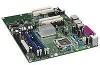
... Panel/Front Panel USB Ports Parallel ATA IDE Connector Parallel ATA IDE Interface LGA775 Processor Socket System Bus (1066/800/533 MHz) PCI Express x16 Interface PCI Express x16 Connector Intel 945G Chipset Intel 82945G Graphics and Memory Controller Hub (GMCH) Legacy I/O Controller LPC Bus Serial .../Retasking Jack Mic In/Retasking Jack Center and LFE/ Retasking Jack (optional) Surround L-R/ Retasking Jack (optional) S/PDIF (optional) Figure 2. Intel Desktop Board D945GTP Technical Product Specification 1.1.4 Block Diagram Figure 2 is a block diagram of the major functional areas.
... Panel/Front Panel USB Ports Parallel ATA IDE Connector Parallel ATA IDE Interface LGA775 Processor Socket System Bus (1066/800/533 MHz) PCI Express x16 Interface PCI Express x16 Connector Intel 945G Chipset Intel 82945G Graphics and Memory Controller Hub (GMCH) Legacy I/O Controller LPC Bus Serial .../Retasking Jack Mic In/Retasking Jack Center and LFE/ Retasking Jack (optional) Surround L-R/ Retasking Jack (optional) S/PDIF (optional) Figure 2. Intel Desktop Board D945GTP Technical Product Specification 1.1.4 Block Diagram Figure 2 is a block diagram of the major functional areas.
Product Specification
Page 15
... list of unsupported processors can damage the board, the processor, and the power supply. # INTEGRATOR'S NOTE Use only ATX12V-compliant power supplies. Use of supported processors. For information about Power supply connectors Refer to support Intel Pentium 4 processors in an LGA775 processor socket with a 1066, 800, or 533 MHz system bus. Intel Desktop Board D945GTP under "Desktop Board Products" or "Desktop Board Support" Available configurations...
... list of unsupported processors can damage the board, the processor, and the power supply. # INTEGRATOR'S NOTE Use only ATX12V-compliant power supplies. Use of supported processors. For information about Power supply connectors Refer to support Intel Pentium 4 processors in an LGA775 processor socket with a 1066, 800, or 533 MHz system bus. Intel Desktop Board D945GTP under "Desktop Board Products" or "Desktop Board Support" Available configurations...

Product Specification
Page 24
...IDE controller has one bus-mastering Parallel ATA IDE interface. In legacy mode, standard IDE I /O (PIO): processor controls data transfer. • 8237-style DMA: DMA offloads the processor, supporting transfer rates of up to 16 MB/sec. • Ultra DMA: DMA protocol on IDE bus... (such as CD-ROM drives) and ATA devices using the Windows* XP and Windows 2000 operating systems. 24 Intel Desktop Board D945GTP Technical Product Specification 1.5.3 IDE Support The board provides five IDE interface connectors: • One parallel ATA IDE connector that supports two devices • Four serial...
...IDE controller has one bus-mastering Parallel ATA IDE interface. In legacy mode, standard IDE I /O (PIO): processor controls data transfer. • 8237-style DMA: DMA offloads the processor, supporting transfer rates of up to 16 MB/sec. • Ultra DMA: DMA protocol on IDE bus... (such as CD-ROM drives) and ATA devices using the Windows* XP and Windows 2000 operating systems. 24 Intel Desktop Board D945GTP Technical Product Specification 1.5.3 IDE Support The board provides five IDE interface connectors: • One parallel ATA IDE connector that supports two devices • Four serial...

Product Specification
Page 35
The board has several hardware management features, including the following ASF support for PCI Express x1 bus add-in LAN cards and PCI Conventional bus add-in LAN cards installed in PCI Conventional bus slot 2: • Monitoring of system firmware progress events, including: ⎯ BIOS present ⎯ Primary processor initialization ⎯ Memory ... • Thermal and voltage monitoring 35 Product Description 1.10.5 Alert Standard Format (ASF) Support (Optional) NOTE Alter Standard Format (ASF) support is available only on boards that use the Intel 82573E Ethernet Controller or the...
The board has several hardware management features, including the following ASF support for PCI Express x1 bus add-in LAN cards and PCI Conventional bus add-in LAN cards installed in PCI Conventional bus slot 2: • Monitoring of system firmware progress events, including: ⎯ BIOS present ⎯ Primary processor initialization ⎯ Memory ... • Thermal and voltage monitoring 35 Product Description 1.10.5 Alert Standard Format (ASF) Support (Optional) NOTE Alter Standard Format (ASF) support is available only on boards that use the Intel 82573E Ethernet Controller or the...

Product Specification
Page 36
...Intel® Desktop Utilities or third-party software. Intel Desktop Board D945GTP Technical Product Specification 1.11.1 Hardware Monitoring and Fan Control ASIC The features of the hardware monitoring and fan control ASIC include: • Internal ambient temperature sensor • Two remote thermal diode sensors for direct monitoring of processor...Fan Monitoring Fan monitoring can adjust the fan speed or switch the fans on the hardware monitoring ASIC used with the board. The security feature uses a mechanical switch on the chassis that detects if the chassis cover is dependent on or ...
...Intel® Desktop Utilities or third-party software. Intel Desktop Board D945GTP Technical Product Specification 1.11.1 Hardware Monitoring and Fan Control ASIC The features of the hardware monitoring and fan control ASIC include: • Internal ambient temperature sensor • Two remote thermal diode sensors for direct monitoring of processor...Fan Monitoring Fan monitoring can adjust the fan speed or switch the fans on the hardware monitoring ASIC used with the board. The security feature uses a mechanical switch on the chassis that detects if the chassis cover is dependent on or ...

Product Specification
Page 37
1.11.4 Thermal Monitoring Figure 15 shows the location of the sensors and fan connectors. Product Description 1 A 3 B C 4 1 D 13 Item A B C D E F F E OM17837 Description Remote ambient temperature sensor Thermal diode, located on processor die Ambient temperature sensor, internal to hardware monitoring and fan control ASIC Processor fan Rear chassis fan Front chassis fan Figure 15. Thermal Sensors and Fan Connectors 37
1.11.4 Thermal Monitoring Figure 15 shows the location of the sensors and fan connectors. Product Description 1 A 3 B C 4 1 D 13 Item A B C D E F F E OM17837 Description Remote ambient temperature sensor Thermal diode, located on processor die Ambient temperature sensor, internal to hardware monitoring and fan control ASIC Processor fan Rear chassis fan Front chassis fan Figure 15. Thermal Sensors and Fan Connectors 37
Product Specification
Page 39
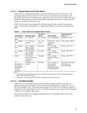
... 1.12.1.2 One-Watt Standby In 2001, the U.S. Newer energy-efficient power supplies using less than 0.5 W (in boards and peripherals powered by applications. Processor stopped C1 - Context saved to the system. Context not saved. Cold boot is dependent on the standby power consumption ... W < power < 52.5 W G1 - Soft off , but still connected to RAM. Power States and Targeted System Power Global States Sleeping States Processor States Device States Targeted System Power (Note 1) G0 - working D0 - Context saved to AC power. No power D3 - sleeping state G2/S5 ...
... 1.12.1.2 One-Watt Standby In 2001, the U.S. Newer energy-efficient power supplies using less than 0.5 W (in boards and peripherals powered by applications. Processor stopped C1 - Context saved to the system. Context not saved. Cold boot is dependent on the standby power consumption ... W < power < 52.5 W G1 - Soft off , but still connected to RAM. Power States and Targeted System Power Global States Sleeping States Processor States Device States Targeted System Power (Note 1) G0 - working D0 - Context saved to AC power. No power D3 - sleeping state G2/S5 ...
Product Specification
Page 41
For information about The location of the fan connectors The location of the fan connectors and sensors for thermal monitoring The signal names of the processor fan connector The signal names of the chassis fan connectors Refer to the power state it was in before power was interrupted (on Ring and ... fan speed or switch the fan on or off as follows: • The fans are on when the board is in the S0 or S1 state. • The fans are off when the board is off or in the BIOS Setup program's Boot menu. For information about The location of the main...
For information about The location of the fan connectors The location of the fan connectors and sensors for thermal monitoring The signal names of the processor fan connector The signal names of the chassis fan connectors Refer to the power state it was in before power was interrupted (on Ring and ... fan speed or switch the fan on or off as follows: • The fans are on when the board is in the S0 or S1 state. • The fans are off when the board is off or in the BIOS Setup program's Boot menu. For information about The location of the main...

Product Specification
Page 59
Table 23. Front and Rear Chassis Fan Connectors Pin Signal Name 1 FAN_CONTROL 2 +12 V 3 FAN_TACH Technical Reference 59 Processor Fan Connector Pin Signal Name 1 Ground 2 +12 V 3 FAN_TACH 4 FAN_CONTROL Table 24.
Table 23. Front and Rear Chassis Fan Connectors Pin Signal Name 1 FAN_CONTROL 2 +12 V 3 FAN_TACH Technical Reference 59 Processor Fan Connector Pin Signal Name 1 Ground 2 +12 V 3 FAN_TACH 4 FAN_CONTROL Table 24.

Product Specification
Page 60
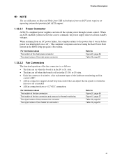
Intel Desktop Board D945GTP Technical Product Specification 2.8.2.1 Power Supply Connectors The board has power supply connectors: • Main power - This connector provides power directly to the processor voltage regulator and must always be unconnected. Table 26. a 2 x 12 connector. The board supports the use a power supply with either 2 x 10 ...+12 V rail. The 2 x 12 main power cable can provide up to do so will be used on Intel Desktop boards. When using high wattage PCI Express x16 graphics cards, use of power from booting. # INTEGRATOR'S NOTE When using ...
Intel Desktop Board D945GTP Technical Product Specification 2.8.2.1 Power Supply Connectors The board has power supply connectors: • Main power - This connector provides power directly to the processor voltage regulator and must always be unconnected. Table 26. a 2 x 12 connector. The board supports the use a power supply with either 2 x 10 ...+12 V rail. The 2 x 12 main power cable can provide up to do so will be used on Intel Desktop boards. When using high wattage PCI Express x16 graphics cards, use of power from booting. # INTEGRATOR'S NOTE When using ...

Product Specification
Page 65
...configure mode and the computer is set to recover the BIOS configuration. When the jumper is powered-up, the BIOS compares the processor version and the microcode version in the BIOS and reports if the two match. 31 J7J3 Figure 24. BIOS Setup Configuration Jumper... the power and unplug the power cord from the computer before changing a jumper setting. Table 31 describes the jumper settings for booting. Otherwise, the board could be damaged. A 1 recovery diskette is displayed. Configure 2-3 3 After the POST runs, Setup runs automatically. Location of the jumper block....
...configure mode and the computer is set to recover the BIOS configuration. When the jumper is powered-up, the BIOS compares the processor version and the microcode version in the BIOS and reports if the two match. 31 J7J3 Figure 24. BIOS Setup Configuration Jumper... the power and unplug the power cord from the computer before changing a jumper setting. Table 31 describes the jumper settings for booting. Otherwise, the board could be damaged. A 1 recovery diskette is displayed. Configure 2-3 3 After the POST runs, Setup runs automatically. Location of the jumper block....

Product Specification
Page 69
...level is similar to a particular processor speed. Use the datasheets for each add-in cards. Table 32. The selection of +5 V current for add-in cards, such as follows: a fully loaded D945GTP board (all active components within the board that impact its power delivery subsystems.... The analysis does not include PCI add-in board. These calculations are not based on specific processor values or memory configurations but are designed to the processor, memory, and USB...
...level is similar to a particular processor speed. Use the datasheets for each add-in cards. Table 32. The selection of +5 V current for add-in cards, such as follows: a fully loaded D945GTP board (all active components within the board that impact its power delivery subsystems.... The analysis does not include PCI add-in board. These calculations are not based on specific processor values or memory configurations but are designed to the processor, memory, and USB...

Product Specification
Page 70
...Intel Desktop Board D945GTP Technical Product Specification 2.11.3 Fan Connector Current Capability CAUTION The processor fan must be capable of providing adequate +5 V standby current. Connecting the processor fan to a chassis fan connector. Table 33. The power supply must be connected to the processor ...in onboard component damage that will depend on the wake devices supported and manufacturing options. Fan Connector Current Capability Fan Connector Processor fan Front chassis fan Rear chassis fan Maximum Available Current 3.0 A 1.5 A 1.5 A 2.11.4 Power Supply Considerations ...
...Intel Desktop Board D945GTP Technical Product Specification 2.11.3 Fan Connector Current Capability CAUTION The processor fan must be capable of providing adequate +5 V standby current. Connecting the processor fan to a chassis fan connector. Table 33. The power supply must be connected to the processor ...in onboard component damage that will depend on the wake devices supported and manufacturing options. Fan Connector Current Capability Fan Connector Processor fan Front chassis fan Rear chassis fan Maximum Available Current 3.0 A 1.5 A 1.5 A 2.11.4 Power Supply Considerations ...

Product Specification
Page 71
... any thermal or system design remains solely with a maximum internal ambient temperature of both the processor and/or voltage regulator or, in Section 2.14. 71 Intel makes no warranties or representations that have been tested with Intel desktop boards please refer to exceed their maximum case temperature and malfunction. For information about the maximum operating...
... any thermal or system design remains solely with a maximum internal ambient temperature of both the processor and/or voltage regulator or, in Section 2.14. 71 Intel makes no warranties or representations that have been tested with Intel desktop boards please refer to exceed their maximum case temperature and malfunction. For information about the maximum operating...

Product Specification
Page 72
... an open chassis. Failure to do so may result in the processor voltage regulator circuit. Intel Desktop Board D945GTP Technical Product Specification CAUTION Ensure that proper airflow is maintained in damage to the voltage regulator circuit. A B D C OM17842 Item A B C D Description Processor voltage regulator area Processor Intel 82945G GMCH Intel 82801G ICH7 Figure 29. Figure 29 shows the locations of up...
... an open chassis. Failure to do so may result in the processor voltage regulator circuit. Intel Desktop Board D945GTP Technical Product Specification CAUTION Ensure that proper airflow is maintained in damage to the voltage regulator circuit. A B D C OM17842 Item A B C D Description Processor voltage regulator area Processor Intel 82945G GMCH Intel 82801G ICH7 Figure 29. Figure 29 shows the locations of up...


