

Product Specification
Page 5
...12 1.2.2 Manufacturing Options 13 1.2.3 Board Layout 14 1.2.4 Block Diagram 16 1.3 Online Support ...17 1.4 Processor ...17 1.5 System Memory ...18 1.5.1 Memory Configurations 19 1.6 Intel® 915P Chipset ...23 1.6.1 USB ...23 1.6.2 IDE Support 23 1.6.3 Real-Time Clock, CMOS...1.8.3 Diskette Drive Controller 27 1.8.4 Keyboard and Mouse Interface 27 1.9 Audio Subsystem ...28 1.9.1 Audio Subsystem Software 28 1.9.2 Audio Connectors 28 1.9.3 8-Channel (7.1) Audio Subsystem 29 1.10 LAN Subsystem...30 1.10.1 Intel® 82562EZ Physical Layer Interface Device 30 1.10.2 Alert Standard ...
...12 1.2.2 Manufacturing Options 13 1.2.3 Board Layout 14 1.2.4 Block Diagram 16 1.3 Online Support ...17 1.4 Processor ...17 1.5 System Memory ...18 1.5.1 Memory Configurations 19 1.6 Intel® 915P Chipset ...23 1.6.1 USB ...23 1.6.2 IDE Support 23 1.6.3 Real-Time Clock, CMOS...1.8.3 Diskette Drive Controller 27 1.8.4 Keyboard and Mouse Interface 27 1.9 Audio Subsystem ...28 1.9.1 Audio Subsystem Software 28 1.9.2 Audio Connectors 28 1.9.3 8-Channel (7.1) Audio Subsystem 29 1.10 LAN Subsystem...30 1.10.1 Intel® 82562EZ Physical Layer Interface Device 30 1.10.2 Alert Standard ...

Product Specification
Page 7
...Mode Configuration with Two DIMMs 20 5. Audio Subsystem Block Diagram 30 11. LAN Connector LED Locations 31 12. Location ... Channel (Interleaved) Mode Configuration with One DIMM 22 8. Thermal Monitoring for IEEE 1394a Connectors 68 20. Processor Heatsink for Front Panel USB Connectors 68 19. Single Channel (Asymmetric) Mode Configuration...Front/Back Panel Audio Connector Options 29 10. I/O Shield Dimensions 71 23. Single Channel (Asymmetric) Mode Configuration with Intel® Rapid BIOS Boot 88 3.8.1 Peripheral Selection and Configuration 88 3.8.2 Intel Rapid BIOS ...
...Mode Configuration with Two DIMMs 20 5. Audio Subsystem Block Diagram 30 11. LAN Connector LED Locations 31 12. Location ... Channel (Interleaved) Mode Configuration with One DIMM 22 8. Thermal Monitoring for IEEE 1394a Connectors 68 20. Processor Heatsink for Front Panel USB Connectors 68 19. Single Channel (Asymmetric) Mode Configuration...Front/Back Panel Audio Connector Options 29 10. I/O Shield Dimensions 71 23. Single Channel (Asymmetric) Mode Configuration with Intel® Rapid BIOS Boot 88 3.8.1 Peripheral Selection and Configuration 88 3.8.2 Intel Rapid BIOS ...
Product Specification
Page 8
...Figure 16 61 17. DMA Channels ...51 11. Front Panel Audio Connector 62 20. Front Panel Connector 66 31. DC Loading ... Certification Markings 81 41. BIOS Setup Program Function Keys 84 43. Intel Desktop Board D915PBL Technical Product Specification Tables 1. Supported Memory Configurations 18... Messages 91 46. Serial Port B Connector (optional 62 21. Processor Fan Connector 63 25. BIOS Setup Configuration Jumper Settings 69 34....Program Menu Bar 84 42. Boot Device Menu Options 87 44. LAN Connector LED States 31 6. Interrupts ...54 14. Serial ATA Connectors ...
...Figure 16 61 17. DMA Channels ...51 11. Front Panel Audio Connector 62 20. Front Panel Connector 66 31. DC Loading ... Certification Markings 81 41. BIOS Setup Program Function Keys 84 43. Intel Desktop Board D915PBL Technical Product Specification Tables 1. Supported Memory Configurations 18... Messages 91 46. Serial Port B Connector (optional 62 21. Processor Fan Connector 63 25. BIOS Setup Configuration Jumper Settings 69 34....Program Menu Bar 84 42. Boot Device Menu Options 87 44. LAN Connector LED States 31 6. Interrupts ...54 14. Serial ATA Connectors ...

Product Specification
Page 11
... 1 Product Description What This Chapter Contains 1.1 PCI Bus Terminology Change 11 1.2 Overview...12 1.3 Online Support ...17 1.4 Processor...17 1.5 System Memory ...18 1.6 Intel® 915P Chipset...23 1.7 PCI Express Connectors 26 1.8 I/O Controller ...26 1.9 Audio Subsystem ...28 1.10 LAN Subsystem ...30 1.11 Hardware Management Subsystem 32 1.12 Power Management 34 1.13 Trusted Platform Module (Optional 41...
... 1 Product Description What This Chapter Contains 1.1 PCI Bus Terminology Change 11 1.2 Overview...12 1.3 Online Support ...17 1.4 Processor...17 1.5 System Memory ...18 1.6 Intel® 915P Chipset...23 1.7 PCI Express Connectors 26 1.8 I/O Controller ...26 1.9 Audio Subsystem ...28 1.10 LAN Subsystem ...30 1.11 Hardware Management Subsystem 32 1.12 Power Management 34 1.13 Trusted Platform Module (Optional 41...
Product Specification
Page 12
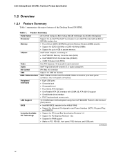
...diskette drive interface • PS/2* keyboard and mouse ports 10/100 Mbits/sec LAN subsystem using the Intel® 82562EZ Platform LAN Connect (PLC) device • Intel/AMI BIOS (resident in an LGA775 socket with an 800 or 533 MHz system bus • Four 240-pin DDR2... Feature Summary Form Factor Processor Memory Chipset Video Audio I/O Control USB IEEE-1394a Interface Peripheral Interfaces LAN Support BIOS Instantly Available PC Technology ATX (12.00 inches by 9.60 inches [304.80 millimeters by 243.84 millimeters]) Support for an Intel® Pentium® 4 processor in the 4 Mbit FWH...
...diskette drive interface • PS/2* keyboard and mouse ports 10/100 Mbits/sec LAN subsystem using the Intel® 82562EZ Platform LAN Connect (PLC) device • Intel/AMI BIOS (resident in an LGA775 socket with an 800 or 533 MHz system bus • Four 240-pin DDR2... Feature Summary Form Factor Processor Memory Chipset Video Audio I/O Control USB IEEE-1394a Interface Peripheral Interfaces LAN Support BIOS Instantly Available PC Technology ATX (12.00 inches by 9.60 inches [304.80 millimeters by 243.84 millimeters]) Support for an Intel® Pentium® 4 processor in the 4 Mbit FWH...

Product Specification
Page 16
... Slot 1 PCI Express x1 Slot 2 Parallel ATA IDE Connector Parallel ATA IDE Interface LGA775 Processor Socket System Bus (800/533 MHz) PCI Express x16 Interface PCI Express x16 Connector Intel 82915P Memory Controller Hub (MCH) Channel A DIMMs (2) Channel B DIMMs (2) Dual-Channel...PS/2 Keyboard Diskette Drive Connector Intel 82801FR I/O Controller Hub (ICH6-R) 4 Mbit Firmware Hub (FWH) Intel 915P Chipset TPM Component (Optional) 10/100 LAN PLC (Optional) LAN Connector DMI Interconnect High Definition Audio Link LAN Connect Interface LPC Bus IEEE-1394a Connectors PCI Bus Serial ATA ...
... Slot 1 PCI Express x1 Slot 2 Parallel ATA IDE Connector Parallel ATA IDE Interface LGA775 Processor Socket System Bus (800/533 MHz) PCI Express x16 Interface PCI Express x16 Connector Intel 82915P Memory Controller Hub (MCH) Channel A DIMMs (2) Channel B DIMMs (2) Dual-Channel...PS/2 Keyboard Diskette Drive Connector Intel 82801FR I/O Controller Hub (ICH6-R) 4 Mbit Firmware Hub (FWH) Intel 915P Chipset TPM Component (Optional) 10/100 LAN PLC (Optional) LAN Connector DMI Interconnect High Definition Audio Link LAN Connect Interface LPC Bus IEEE-1394a Connectors PCI Bus Serial ATA ...

Product Specification
Page 17
... of supported processors. Intel Desktop Board D915PBL under "Desktop Board Products" or "Desktop Board Support" Available configurations for the Desktop Board D915PBL Processor data sheets ICH6-R addressing Custom splash screens Audio software and utilities LAN software and drivers Visit this World Wide Web site: http://www.intel.com/design/motherbd http://support.intel.com/support/motherboards/desktop http...
... of supported processors. Intel Desktop Board D915PBL under "Desktop Board Products" or "Desktop Board Support" Available configurations for the Desktop Board D915PBL Processor data sheets ICH6-R addressing Custom splash screens Audio software and utilities LAN software and drivers Visit this World Wide Web site: http://www.intel.com/design/motherbd http://support.intel.com/support/motherboards/desktop http...

Product Specification
Page 23
...shielded cable that meets the requirements for all ports. For information about The Intel 915P chipset Resources used by the chipset Refer to http://developer.intel.com/ Chapter 2 1.6.1 USB The board supports up to the audio connectors • Four ports are implemented with DMI interconnect • Firmware... The location of the BIOS. The ICH6-R is a centralized controller for the board's I /O (PIO): processor controls data transfer. • 8237-style DMA: DMA offloads the processor, supporting transfer rates of up to eight USB 2.0 ports, supports UHCI and EHCI, and uses UHCI-
...shielded cable that meets the requirements for all ports. For information about The Intel 915P chipset Resources used by the chipset Refer to http://developer.intel.com/ Chapter 2 1.6.1 USB The board supports up to the audio connectors • Four ports are implemented with DMI interconnect • Firmware... The location of the BIOS. The ICH6-R is a centralized controller for the board's I /O (PIO): processor controls data transfer. • 8237-style DMA: DMA offloads the processor, supporting transfer rates of up to eight USB 2.0 ports, supports UHCI and EHCI, and uses UHCI-

Product Specification
Page 31
...the following ASF support for PCI Express x1 bus add-in LAN cards and PCI Conventional bus add-in LAN cards installed in Figure 11 below). LAN link is occurring. Table 5. LAN activity is established. LAN Connector LED Locations Table 5 describes the LED states when the... with Integrated LEDs Two LEDs are built into the RJ-45 LAN connector (shown in PCI Conventional bus slot 2: • Monitoring of system firmware progress events, including: BIOS present Primary processor initialization Memory initialization Video initialization PCI resource configuration Hard-disk initialization ...
...the following ASF support for PCI Express x1 bus add-in LAN cards and PCI Conventional bus add-in LAN cards installed in Figure 11 below). LAN link is occurring. Table 5. LAN activity is established. LAN Connector LED Locations Table 5 describes the LED states when the... with Integrated LEDs Two LEDs are built into the RJ-45 LAN connector (shown in PCI Conventional bus slot 2: • Monitoring of system firmware progress events, including: BIOS present Primary processor initialization Memory initialization Video initialization PCI resource configuration Hard-disk initialization ...

Product Specification
Page 32
...off as needed • SMBus interface For information about Obtaining LAN software and drivers Refer to Section 1.3, page 17 1.10.4 Intel® Wireless Connect Technology (Optional) Intel® Wireless Connect Technology is available for Intel 82801FBW (ICH6RW) based SKUs that can support up to 16 ... fan control ASIC include: • Internal ambient temperature sensor • Two remote thermal diode sensors for direct monitoring of processor temperature and ambient temperature sensing • Power supply monitoring of the fan connectors and sensors for thermal monitoring Refer to be...
...off as needed • SMBus interface For information about Obtaining LAN software and drivers Refer to Section 1.3, page 17 1.10.4 Intel® Wireless Connect Technology (Optional) Intel® Wireless Connect Technology is available for Intel 82801FBW (ICH6RW) based SKUs that can support up to 16 ... fan control ASIC include: • Internal ambient temperature sensor • Two remote thermal diode sensors for direct monitoring of processor temperature and ambient temperature sensing • Power supply monitoring of the fan connectors and sensors for thermal monitoring Refer to be...

Product Specification
Page 33
Thermal Monitoring for the D915PBL board. 13 3 1 A CB 4 1 D 13 1 3 Item A B C D E F G H HG F E OM17055 Description Thermal diode, located on processor die Remote ambient temperature sensor Ambient temperature sensor, internal to hardware monitoring and fan control ASIC Processor fan Rear chassis fan 1 Front chassis fan ATX fan (optional) Rear chassis fan 2 Figure 12. Product Description 1.11.2 Thermal Monitoring Figure 12 shows the location of the sensors and fan connectors for D915PBL Board 33
Thermal Monitoring for the D915PBL board. 13 3 1 A CB 4 1 D 13 1 3 Item A B C D E F G H HG F E OM17055 Description Thermal diode, located on processor die Remote ambient temperature sensor Ambient temperature sensor, internal to hardware monitoring and fan control ASIC Processor fan Rear chassis fan 1 Front chassis fan ATX fan (optional) Rear chassis fan 2 Figure 12. Product Description 1.11.2 Thermal Monitoring Figure 12 shows the location of the sensors and fan connectors for D915PBL Board 33
Product Specification
Page 36
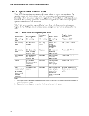
...No power No power No power No power Device States D0 - device specification specific. Total system power is required. Intel Desktop Board D915PBL Technical Product Specification 1.12.1.1 System States and Power States Under ACPI, the operating system directs all system... and device power state transitions. Devices that are being used can be turned off . Processor stopped S3 - S4 - No power to RAM. working S1 - Targeted System Power (Note 1) Full power > 30 W 5 W < power < 52.5 W Power < 5 W (Note 2) ...
...No power No power No power No power Device States D0 - device specification specific. Total system power is required. Intel Desktop Board D915PBL Technical Product Specification 1.12.1.1 System States and Power States Under ACPI, the operating system directs all system... and device power state transitions. Devices that are being used can be turned off . Processor stopped S3 - S4 - No power to RAM. working S1 - Targeted System Power (Note 1) Full power > 30 W 5 W < power < 52.5 W Power < 5 W (Note 2) ...

Product Specification
Page 38
...about The location of the fan connectors The location of the fan connectors and sensors for thermal monitoring The signal names of the processor fan connector The signal names of the chassis fan connectors Refer to Figure 16, page 60 Figure 12, page 33 Table 24...off when the board is wired to a fan tachometer input of providing adequate +5 V standby current. The LAN network adapter monitors network traffic at the Media Independent Interface. Intel Desktop Board D915PBL Technical Product Specification Resume on Ring enables telephony devices to access the computer when it was ...
...about The location of the fan connectors The location of the fan connectors and sensors for thermal monitoring The signal names of the processor fan connector The signal names of the chassis fan connectors Refer to Figure 16, page 60 Figure 12, page 33 Table 24...off when the board is wired to a fan tachometer input of providing adequate +5 V standby current. The LAN network adapter monitors network traffic at the Media Independent Interface. Intel Desktop Board D915PBL Technical Product Specification Resume on Ring enables telephony devices to access the computer when it was ...

Product Specification
Page 63
SCSI Hard Drive Activity LED Connector (Optional) Pin Signal Name 1 SCSI_ACT# 2 No connect Table 23. Processor Fan Connector Pin Signal Name 1 Ground 2 +12 V 3 FAN_TACH 4 FAN_CONTROL 2.8.2.1 Chassis Fan Connectors The board has three standard and one optional chassis fan ...connectors: • Front chassis fan • Rear chassis fan 1 • Rear chassis fan 2 • ATX fan connector (optional) Table 25 lists the signal names for the chassis fan connectors. Table 25. These signal names apply to all chassis fan connectors...
SCSI Hard Drive Activity LED Connector (Optional) Pin Signal Name 1 SCSI_ACT# 2 No connect Table 23. Processor Fan Connector Pin Signal Name 1 Ground 2 +12 V 3 FAN_TACH 4 FAN_CONTROL 2.8.2.1 Chassis Fan Connectors The board has three standard and one optional chassis fan ...connectors: • Front chassis fan • Rear chassis fan 1 • Rear chassis fan 2 • ATX fan connector (optional) Table 25 lists the signal names for the chassis fan connectors. Table 25. These signal names apply to all chassis fan connectors...

Product Specification
Page 64
... 2 x 12 main power cables. When using high wattage PCI Express x16 graphics cards, use a power supply with a 2 x 10 main power cable, attach that cable on Intel Desktop boards. Main Power Connector Pin Signal Name 1 +3.3 V 2 +3.3 V 3 Ground 4 +5 V 5 Ground 6 +5 V 7 Ground 8 PWRGD (Power Good) 9 +5... W of power from booting. • Alternate power - This connector is to the processor voltage regulator and must always be unconnected. 64 Intel Desktop Board D915PBL Technical Product Specification 2.8.2.2 Power Supply Connectors The board has three power supply...
... 2 x 12 main power cables. When using high wattage PCI Express x16 graphics cards, use a power supply with a 2 x 10 main power cable, attach that cable on Intel Desktop boards. Main Power Connector Pin Signal Name 1 +3.3 V 2 +3.3 V 3 Ground 4 +5 V 5 Ground 6 +5 V 7 Ground 8 PWRGD (Power Good) 9 +5... W of power from booting. • Alternate power - This connector is to the processor voltage regulator and must always be unconnected. 64 Intel Desktop Board D915PBL Technical Product Specification 2.8.2.2 Power Supply Connectors The board has three power supply...

Product Specification
Page 69
... off the power and unplug the power cord from the computer before changing a jumper setting. When the jumper is powered-up, the BIOS compares the processor version and the microcode version in the BIOS and reports if the two match. 1 3 J8J4 Figure 20.
... off the power and unplug the power cord from the computer before changing a jumper setting. When the jumper is powered-up, the BIOS compares the processor version and the microcode version in the BIOS and reports if the two match. 1 3 J8J4 Figure 20.

Product Specification
Page 72
...include PCI add-in onboard component damage that will halt fan operation. Table 35. These calculations are not based on specific processor values or memory configurations but are based on the board that is similar to a chassis fan connector. DC Loading Characteristics...to an environment with a 500 mA current draw per USB port. Connecting the processor fan to determine the overall system power requirements. This data is designed to a particular processor speed. Intel Desktop Board D915PBL Technical Product Specification 2.11 Electrical Considerations 2.11.1 DC Loading Table ...
...include PCI add-in onboard component damage that will halt fan operation. Table 35. These calculations are not based on specific processor values or memory configurations but are based on the board that is similar to a chassis fan connector. DC Loading Characteristics...to an environment with a 500 mA current draw per USB port. Connecting the processor fan to determine the overall system power requirements. This data is designed to a particular processor speed. Intel Desktop Board D915PBL Technical Product Specification 2.11 Electrical Considerations 2.11.1 DC Loading Table ...

Product Specification
Page 74
... result in reduced performance of 38 oC at the processor fan inlet is a requirement. Processor Heatsink for determining the adequacy of any thermal or system design remains solely with the reader. Intel makes no warranties or representations that have been tested with...list of chassis that merely following website: http://developer.intel.com/design/motherbd/cooling.htm All responsibility for Omni-directional Airflow CAUTION Failure to maintain required airflow across the processor voltage regulator area. Use a processor heatsink that the ambient temperature does not exceed the board...
... result in reduced performance of 38 oC at the processor fan inlet is a requirement. Processor Heatsink for determining the adequacy of any thermal or system design remains solely with the reader. Intel makes no warranties or representations that have been tested with...list of chassis that merely following website: http://developer.intel.com/design/motherbd/cooling.htm All responsibility for Omni-directional Airflow CAUTION Failure to maintain required airflow across the processor voltage regulator area. Use a processor heatsink that the ambient temperature does not exceed the board...

Product Specification
Page 75
The processor voltage regulator area (item A in Figure 24) can reach a temperature of the localized high temperature zones. Figure 24 shows the locations of up to 85 oC in damage to do so may result in an open chassis. Localized High Temperature Zones OM17063 75 A B D C Item A B C D Description Processor voltage regulator area Processor Intel 82915P MCH Intel 82801FR ICH6-R Figure 24. Failure to the voltage regulator circuit. Technical Reference CAUTION Ensure that proper airflow is maintained in the processor voltage regulator circuit.
The processor voltage regulator area (item A in Figure 24) can reach a temperature of the localized high temperature zones. Figure 24 shows the locations of up to 85 oC in damage to do so may result in an open chassis. Localized High Temperature Zones OM17063 75 A B D C Item A B C D Description Processor voltage regulator area Processor Intel 82915P MCH Intel 82801FR ICH6-R Figure 24. Failure to the voltage regulator circuit. Technical Reference CAUTION Ensure that proper airflow is maintained in the processor voltage regulator circuit.

Product Specification
Page 76
... 110,262 hours. 76 Table 36. Thermal Considerations for Components Component Intel Pentium 4 processor Intel 82915P MCH Intel 82801FR ICH6-R Maximum Case Temperature For processor case temperature, see processor datasheets and processor specification updates 99 oC (under bias) 110 oC (under bias) For information about Intel Pentium 4 processor datasheets and specification updates Refer to estimate repair rates and spare...
... 110,262 hours. 76 Table 36. Thermal Considerations for Components Component Intel Pentium 4 processor Intel 82915P MCH Intel 82801FR ICH6-R Maximum Case Temperature For processor case temperature, see processor datasheets and processor specification updates 99 oC (under bias) 110 oC (under bias) For information about Intel Pentium 4 processor datasheets and specification updates Refer to estimate repair rates and spare...


