
User Manual
Page 1
630TCF/630TCN USER'S MANUAL M/B For Pentium III Tualatin Processor NO. G03-630TCFR3A Release date: January 2002 Trademark: * Pentium is registered trademark and MMX is a trademark of Intel Corporation, the other names and brands are the property of their respective owners * Specifications and Information contained in this documentation are furnished for information use only, and are subject to change at any time without notice, and should not be construed as a commitment by manufacturer.
630TCF/630TCN USER'S MANUAL M/B For Pentium III Tualatin Processor NO. G03-630TCFR3A Release date: January 2002 Trademark: * Pentium is registered trademark and MMX is a trademark of Intel Corporation, the other names and brands are the property of their respective owners * Specifications and Information contained in this documentation are furnished for information use only, and are subject to change at any time without notice, and should not be construed as a commitment by manufacturer.
User Manual
Page 2
TABLE OF CONTENT USER'S NOTICE 1 MANUAL REVISION INFORMATION 2 THERMAL SOLUTIONS 2 CHAPTER 1 INTRODUCTION OF 630TCF/630TCN MOTHERBOARD 1-1 FEATURE OF MOTHERBOARD 3 1-2 SPECIFICATION 4 1-3 PERFORMANCE LIST 5 1-4 LAYOUT DIAGRAM & JUMPER SETTING 6 CHAPTER 2 HARDWARE INSTALLATION 2-1 HARDWARE INSTALLATION STEPS 8 2-2 CHECKING MOTHERBOARD'S JUMPER SETTING 8 2-3 INSTALL CPU 10 2-3-1 ABOUT PENTIUM & CELERON™ 370-PIN CPU 10 2-3-2 SETTING CPU BUS CLOCK & MEMORY CLOCK JUMPER ... 11 2-3-3 INSTALL CPU 12 2-3-4 OVERCLOCK RUNNING 13 2-4 INSTALL MEMORY 14 2-5 EXPANSION CARD 15 ...
TABLE OF CONTENT USER'S NOTICE 1 MANUAL REVISION INFORMATION 2 THERMAL SOLUTIONS 2 CHAPTER 1 INTRODUCTION OF 630TCF/630TCN MOTHERBOARD 1-1 FEATURE OF MOTHERBOARD 3 1-2 SPECIFICATION 4 1-3 PERFORMANCE LIST 5 1-4 LAYOUT DIAGRAM & JUMPER SETTING 6 CHAPTER 2 HARDWARE INSTALLATION 2-1 HARDWARE INSTALLATION STEPS 8 2-2 CHECKING MOTHERBOARD'S JUMPER SETTING 8 2-3 INSTALL CPU 10 2-3-1 ABOUT PENTIUM & CELERON™ 370-PIN CPU 10 2-3-2 SETTING CPU BUS CLOCK & MEMORY CLOCK JUMPER ... 11 2-3-3 INSTALL CPU 12 2-3-4 OVERCLOCK RUNNING 13 2-4 INSTALL MEMORY 14 2-5 EXPANSION CARD 15 ...
User Manual
Page 3
... SETUP 37 3-9-1 IRQ RESOURCES 38 3-10 PC HEALTH STATUS 39 3-11 FREQUENCY/VOLTAGE CONTROL 39 3-12 LOAD STANDARD/OPTIMIZED DEFAULTS 40 3-13 SET SUPERVISOR/USER PASSWORD 41 CHAPTER 4 DRIVER & FREE PROGRAM INSTALLATION MAGIC INSTALL SUPPORTS WINDOWS 95/98/98SE/NT4.0/2000 ........ 42 4-1 VGA INSTALL SIS 630 VGA DRIVER ... INSTALL SIS 900 PCI FAST ETHERNET DRIVER 46 4-4 SOUND INSTALL SIS 7018 AC'97 AUDIO DRIVER AND APPLICATION SOFTWARE 47 4-5 PC-CILLIN INSTALL PC-CILLIN98 ANTI-VIRUS SOFTWARE AND APPLICATION PROGRAM 49 4-6 HOW TO DISABLE ON-BOARD SOUND 50 4-7 HOW TO UPDATE ...
... SETUP 37 3-9-1 IRQ RESOURCES 38 3-10 PC HEALTH STATUS 39 3-11 FREQUENCY/VOLTAGE CONTROL 39 3-12 LOAD STANDARD/OPTIMIZED DEFAULTS 40 3-13 SET SUPERVISOR/USER PASSWORD 41 CHAPTER 4 DRIVER & FREE PROGRAM INSTALLATION MAGIC INSTALL SUPPORTS WINDOWS 95/98/98SE/NT4.0/2000 ........ 42 4-1 VGA INSTALL SIS 630 VGA DRIVER ... INSTALL SIS 900 PCI FAST ETHERNET DRIVER 46 4-4 SOUND INSTALL SIS 7018 AC'97 AUDIO DRIVER AND APPLICATION SOFTWARE 47 4-5 PC-CILLIN INSTALL PC-CILLIN98 ANTI-VIRUS SOFTWARE AND APPLICATION PROGRAM 49 4-6 HOW TO DISABLE ON-BOARD SOUND 50 4-7 HOW TO UPDATE ...
User Manual
Page 5
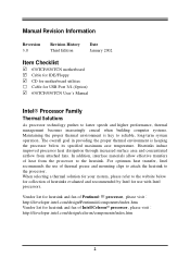
.../design/Pentiumiii/components/index.htm Vendor list for heatsink and fan of Pentium® !!! In addition, interface materials allow effective transfers of heat from attached fans. Heatsinks induce improved processor heat dissipation through increased surface area and concentrated airflow from the processor to the heatsink. For optimum heat transfer, Intel recommends the use with Intel processors. The overall goal in providing the proper thermal environment...
.../design/Pentiumiii/components/index.htm Vendor list for heatsink and fan of Pentium® !!! In addition, interface materials allow effective transfers of heat from attached fans. Heatsinks induce improved processor heat dissipation through increased surface area and concentrated airflow from the processor to the heatsink. For optimum heat transfer, Intel recommends the use with Intel processors. The overall goal in providing the proper thermal environment...

User Manual
Page 6
... integrating the Ultra AGP technology and advanced 128-bit graphic display interface, SiS 630 delivers AGP 4X performance and up to 100MB/s for data transfer rate. This motherboard use the newest SiS 630T chipset provides a high performance/low cost solution for use Intel's new generation Pentium processors, which utilize the Socket 370 design supports PentiumIII/Celeron Tualatin FC-PGA processors, and the memory size expandable to 1GB...
... integrating the Ultra AGP technology and advanced 128-bit graphic display interface, SiS 630 delivers AGP 4X performance and up to 100MB/s for data transfer rate. This motherboard use the newest SiS 630T chipset provides a high performance/low cost solution for use Intel's new generation Pentium processors, which utilize the Socket 370 design supports PentiumIII/Celeron Tualatin FC-PGA processors, and the memory size expandable to 1GB...
User Manual
Page 7
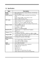
1-2 Specification Spec Description Design ∗ Micro ATX form factor 4 layers PCB size: 24.5x19.0cm Chipset ∗ SiS 630T Chipset Clock Generator ∗ Support 66/100/133MHz system Bus Clock (CPU Bus Clock) Support 100/133 MHz system memory clock Support 33MHz PCI Bus clock CPU Socket Memory Socket Expansion Slot Integrate VGA Integrate IDE ∗ Support Pentium III 500∼1.2GHz processor ∗ Support Celeron...
1-2 Specification Spec Description Design ∗ Micro ATX form factor 4 layers PCB size: 24.5x19.0cm Chipset ∗ SiS 630T Chipset Clock Generator ∗ Support 66/100/133MHz system Bus Clock (CPU Bus Clock) Support 100/133 MHz system memory clock Support 33MHz PCI Bus clock CPU Socket Memory Socket Expansion Slot Integrate VGA Integrate IDE ∗ Support Pentium III 500∼1.2GHz processor ∗ Support Celeron...
User Manual
Page 8
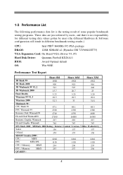
... different testing data values gotten by users (the different Hardware & Software configuration will result in different benchmark testing results.) CPU: Intel PIII 866MHz FC-PGA package DRAM: 128M SDRAM x2 (Hyundai GM 72V66841ET75) VGA Expansion Card: On Board VGA (Driver V1.05) Hard Disk Driver: Quantum Fireball KX20A11 BIOS: Award Optimal default OS: Win 98SE Performance Test...
... different testing data values gotten by users (the different Hardware & Software configuration will result in different benchmark testing results.) CPU: Intel PIII 866MHz FC-PGA package DRAM: 128M SDRAM x2 (Hyundai GM 72V66841ET75) VGA Expansion Card: On Board VGA (Driver V1.05) Hard Disk Driver: Quantum Fireball KX20A11 BIOS: Award Optimal default OS: Win 98SE Performance Test...

User Manual
Page 11
Connect Ribbon cables, Panel wires, and power supply 6. Setup BIOS 7. Check motherboard setting 2. Install Expansion cards 5. Install software driver & utility 2-2 Checking Motherboard's Jumper Setting 1. Install Memory 4. Table as below: CPU/SDRAM (MHz) AUTO 66/66 66/100 100/100 ...AMR AMR Slot 32-bit PCI Local Bus Expansion slots p.15 Modem Riser Card slot Chapter 2 Hardware installation 2-1 Hardware installation Steps Before using your computer, you had better complete the following steps: 1. CPU & SDRAM Clock Setting : JP2, JP10, JP11 The motherboard's CPU & SDRAM memory ...
Connect Ribbon cables, Panel wires, and power supply 6. Setup BIOS 7. Check motherboard setting 2. Install Expansion cards 5. Install software driver & utility 2-2 Checking Motherboard's Jumper Setting 1. Install Memory 4. Table as below: CPU/SDRAM (MHz) AUTO 66/66 66/100 100/100 ...AMR AMR Slot 32-bit PCI Local Bus Expansion slots p.15 Modem Riser Card slot Chapter 2 Hardware installation 2-1 Hardware installation Steps Before using your computer, you had better complete the following steps: 1. CPU & SDRAM Clock Setting : JP2, JP10, JP11 The motherboard's CPU & SDRAM memory ...
User Manual
Page 13
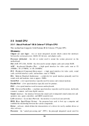
... modems; USB - Driver - the slot or socket used to mount the system processor on the motherboard. the slots used to mount adapter cards and system RAM. Peripheral Component Interconnect - Sound (interface) - the interface between the system processor, RAM, I/O devises, and adapter cards. Local Area Network - 2-3 Install CPU 2-3-1 About Pentium III & Celeron™ 370-pin CPU This motherboard supports both Pentium III & Celeron 370 pins CPU. ISA - Processor - the principal...
... modems; USB - Driver - the slot or socket used to mount the system processor on the motherboard. the slots used to mount adapter cards and system RAM. Peripheral Component Interconnect - Sound (interface) - the interface between the system processor, RAM, I/O devises, and adapter cards. Local Area Network - 2-3 Install CPU 2-3-1 About Pentium III & Celeron™ 370-pin CPU This motherboard supports both Pentium III & Celeron 370 pins CPU. ISA - Processor - the principal...

User Manual
Page 14
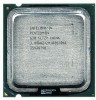
...generator for the front side bus frequency and SDRAM frequency setting as shown from the packing Pentium III 370 pins FC-PGA On the surface of the CPU as shown on the right picture, under the word of "PENTIUM III" the code is: RB 80526 P2 866 256 RB : FC...the voltage for the CPU 2-3-2 Setting CPU Bus Clock & Memory Clock Jumper Setting the front side bus frequency and SDRAM frequency The motherboard uses jumper JP2 for CPU, DRAM and PCI BUS. CPU L2 Cache The flash memory inside the CPU, normally Pentium III CPU has 256K or above, while Celeron CPU will form the CPU Internal Frequency. The ...
...generator for the front side bus frequency and SDRAM frequency setting as shown from the packing Pentium III 370 pins FC-PGA On the surface of the CPU as shown on the right picture, under the word of "PENTIUM III" the code is: RB 80526 P2 866 256 RB : FC...the voltage for the CPU 2-3-2 Setting CPU Bus Clock & Memory Clock Jumper Setting the front side bus frequency and SDRAM frequency The motherboard uses jumper JP2 for CPU, DRAM and PCI BUS. CPU L2 Cache The flash memory inside the CPU, normally Pentium III CPU has 256K or above, while Celeron CPU will form the CPU Internal Frequency. The ...

User Manual
Page 15
... Example: Using a Pentium III 866 CPU with front side bus frequency of 133MHz and PC-133 SDRAM module, the setting of JP2 are 1-2 closed, 3-4 closed, 5-6 closed for two of the four corners, the CPU will only fit in the orientation as shown below. The CPU that there is sufficient air circulation across the processor's heatsink and CPU cooling FAN is...
... Example: Using a Pentium III 866 CPU with front side bus frequency of 133MHz and PC-133 SDRAM module, the setting of JP2 are 1-2 closed, 3-4 closed, 5-6 closed for two of the four corners, the CPU will only fit in the orientation as shown below. The CPU that there is sufficient air circulation across the processor's heatsink and CPU cooling FAN is...
User Manual
Page 16
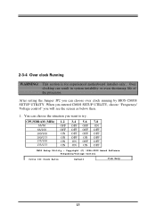
...motherboard installer only. 2-3-4 Over clock Running WARNING! Over clocking can choose over clock running by BIOS CMOS SETUP UTILITY. Copyright (C) 1984-2000 Award Software Frequency/Voltage Control Cyrix III Clock Ratio Default Item Help 13 You can choose the situation you can result in system instability or even shortening life of the processor. CPU... OFF 133/100 ON ON OFF OFF 133/133 ON ON ON OFF CMOS Setup Utility - After setting the Jumper JP2 you want to try. When you entered CMOS SETUP UTILITY, choose "Frequency/ Voltage control" you will see the screen as below ...
...motherboard installer only. 2-3-4 Over clock Running WARNING! Over clocking can choose over clock running by BIOS CMOS SETUP UTILITY. Copyright (C) 1984-2000 Award Software Frequency/Voltage Control Cyrix III Clock Ratio Default Item Help 13 You can choose the situation you can result in system instability or even shortening life of the processor. CPU... OFF 133/100 ON ON OFF OFF 133/133 ON ON ON OFF CMOS Setup Utility - After setting the Jumper JP2 you want to try. When you entered CMOS SETUP UTILITY, choose "Frequency/ Voltage control" you will see the screen as below ...

User Manual
Page 19
...2 LAN (for ISA or PCI devices. 2-5-3 Interrupt Request Table For This Motherboard Interrupt request are already in use . Standard Interrupt Assignments IRQ 0 1 2 3 * 4 * 5 ... Compatible Mouse Port Numeric Data Processor Primary... IDE Channel Secondary IDE Channel * These IRQs are usually available for 630TCF Only) INT A INT B Shared Shared INT C Shared Shared INT D Shared Shared Shared IMPORTANT! Conflicts will make sure that the drivers support...
...2 LAN (for ISA or PCI devices. 2-5-3 Interrupt Request Table For This Motherboard Interrupt request are already in use . Standard Interrupt Assignments IRQ 0 1 2 3 * 4 * 5 ... Compatible Mouse Port Numeric Data Processor Primary... IDE Channel Secondary IDE Channel * These IRQs are usually available for 630TCF Only) INT A INT B Shared Shared INT C Shared Shared INT D Shared Shared Shared IMPORTANT! Conflicts will make sure that the drivers support...

User Manual
Page 28
To exit the Help Window, press . 3-3 The Main Menu Once you to specify your system's performance. Copyright(C) 1984-2000 Award Software Standard CMOS Features Frequency/Voltage Control Advanced BIOS Features Load optimized Defaults Advanced Chipset Features Load Standard Defaults Integrated Peripherals Set Supervisor Password Power Management Setup Set User Password PnP/PCI Configurations Save & Exit Setup PC Health Status Exit Without...
To exit the Help Window, press . 3-3 The Main Menu Once you to specify your system's performance. Copyright(C) 1984-2000 Award Software Standard CMOS Features Frequency/Voltage Control Advanced BIOS Features Load optimized Defaults Advanced Chipset Features Load Standard Defaults Integrated Peripherals Set Supervisor Password Power Management Setup Set User Password PnP/PCI Configurations Save & Exit Setup PC Health Status Exit Without...

User Manual
Page 31
... Warning CPU Internal Cache External Cache CPU L2 Cache ECC Checking Processor Number Feature Quick Power On Self Test First Boot Device Second Boot Device Third Boot Device Fourth Boot Device Swap Floppy Drive Boot Up Floppy Seek Boot Up NumLock Status Gate A20 Option Typematic Rate Setting Typematic ... table. If this function is enabled and someone attempt to write data into this area, BIOS will show a warning message on screen and alarm beep. External Cache Choose Enabled or Disabled. CMOS Setup Utility - Enabled Activates automatically when the system boots up causing a...
... Warning CPU Internal Cache External Cache CPU L2 Cache ECC Checking Processor Number Feature Quick Power On Self Test First Boot Device Second Boot Device Third Boot Device Fourth Boot Device Swap Floppy Drive Boot Up Floppy Seek Boot Up NumLock Status Gate A20 Option Typematic Rate Setting Typematic ... table. If this function is enabled and someone attempt to write data into this area, BIOS will show a warning message on screen and alarm beep. External Cache Choose Enabled or Disabled. CMOS Setup Utility - Enabled Activates automatically when the system boots up causing a...

User Manual
Page 32
This option enables the Level 2 cache memory ECC (error check correction). Disabled this will check the CPU Serial number. Enabled (default) Enable quick POST Disabled Normal POST First/Second/Third/Fourth Boot Device The BIOS attempts to Enabled. Boot Up NumLock Status The default value is for Pentium III processor. The settings are Floppy, LS/ZIP, HDD-0/HDD...
This option enables the Level 2 cache memory ECC (error check correction). Disabled this will check the CPU Serial number. Enabled (default) Enable quick POST Disabled Normal POST First/Second/Third/Fourth Boot Device The BIOS attempts to Enabled. Boot Up NumLock Status The default value is for Pentium III processor. The settings are Floppy, LS/ZIP, HDD-0/HDD...

User Manual
Page 34
...to use this memory area, a system error may result. Memory Hole at F0000h-FFFFFh, resulting in better system performance. The settings are : Enabled and Disabled. The settings are : Enabled and Disabled. The settings are : Enabled and Disabled. System BIOS Cacheable Selecting Enabled allows caching ...RAS to support delay transactions cycles. The choice is reserved, it cannot be cached. When this area is either Disabled or Enabled. 3-6-1 Advanced DRAM Control CMOS Setup Utility - The user information of the video BIOS, resulting in better system performance. Select ...
...to use this memory area, a system error may result. Memory Hole at F0000h-FFFFFh, resulting in better system performance. The settings are : Enabled and Disabled. The settings are : Enabled and Disabled. The settings are : Enabled and Disabled. System BIOS Cacheable Selecting Enabled allows caching ...RAS to support delay transactions cycles. The choice is reserved, it cannot be cached. When this area is either Disabled or Enabled. 3-6-1 Advanced DRAM Control CMOS Setup Utility - The user information of the video BIOS, resulting in better system performance. Select ...

User Manual
Page 36
... Input/Output) fields let you set a PIO mode (0-4) for automatic detection of the optimal number of the four IDE devices that the onboard IDE interface supports. Primary/Secondary Master/Slave UDMA ...driver). 3-7-1 OnChip IDE Function CMOS Setup Utility - The settings are : Auto, Disabled. The settings are : Auto, Mode 0, Mode 1, Mode 2, Mode 3, Mode 4. If your hard drive and your IDE hard drive supports block mode (most new drives do), select Enabled for each channel separately. Select Both to enable BIOS support. In Auto mode, the system automatically determines the best...
... Input/Output) fields let you set a PIO mode (0-4) for automatic detection of the optimal number of the four IDE devices that the onboard IDE interface supports. Primary/Secondary Master/Slave UDMA ...driver). 3-7-1 OnChip IDE Function CMOS Setup Utility - The settings are : Auto, Disabled. The settings are : Auto, Mode 0, Mode 1, Mode 2, Mode 3, Mode 4. If your hard drive and your IDE hard drive supports block mode (most new drives do), select Enabled for each channel separately. Select Both to enable BIOS support. In Auto mode, the system automatically determines the best...

User Manual
Page 42
... to automatically configure all of device using a Plug and Play operating system such as Windows95/98. The settings are Enabled, Disabled. 3-9-1 IRQ Resources CMOS Setup Utility - Resource Controlled By The ...compatible devices. Select Enabled to Reset Extended System Configuration Data (ESCD) when you exit Setup if you leave this field at Disabled. The settings are : Auto(ESCD), Manual. Select Enabled to reset Extended System Configuration Data (ESCD) when you exit Setup if you are : Enabled and Disabled. Reset Configuration Data Normally, you have installed a new...
... to automatically configure all of device using a Plug and Play operating system such as Windows95/98. The settings are Enabled, Disabled. 3-9-1 IRQ Resources CMOS Setup Utility - Resource Controlled By The ...compatible devices. Select Enabled to Reset Extended System Configuration Data (ESCD) when you exit Setup if you leave this field at Disabled. The settings are : Auto(ESCD), Manual. Select Enabled to reset Extended System Configuration Data (ESCD) when you exit Setup if you are : Enabled and Disabled. Reset Configuration Data Normally, you have installed a new...
User Manual
Page 46
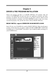
... not appear, double-click MY COMPUTER / double-click CD-ROM drive or click START / click RUN / type X:\SETUP.EXE (assuming X is installed, and which hardware is your system can function properly. This CD consists of all DRIVERS you need and some free application programs and utility programs. In addition, this auto detect software MAGIC...
... not appear, double-click MY COMPUTER / double-click CD-ROM drive or click START / click RUN / type X:\SETUP.EXE (assuming X is installed, and which hardware is your system can function properly. This CD consists of all DRIVERS you need and some free application programs and utility programs. In addition, this auto detect software MAGIC...


