

Data Sheet
Page 1
Intel® Pentium® 4 Processors 570/571, 560/561, 550/551, 540/541, 530/531 and 520/521∆ Supporting Hyper-Threading Technology1 Datasheet On 90 nm Process in 775-land LGA Package and supporting Intel® Extended Memory 64 TechnologyΦ May 2005 Document Number: 302351-004
Intel® Pentium® 4 Processors 570/571, 560/561, 550/551, 540/541, 530/531 and 520/521∆ Supporting Hyper-Threading Technology1 Datasheet On 90 nm Process in 775-land LGA Package and supporting Intel® Extended Memory 64 TechnologyΦ May 2005 Document Number: 302351-004
Data Sheet
Page 2
...computer system with Execute Disable Bit capability and a supporting operating system. Intel reserves these for future definition and shall have no responsibility whatsoever for Intel EM64T. The Intel® Pentium® 4 processor in the United States and other countries. *Other names and brands... at any features or instructions marked "reserved" or "undefined." Intel, Pentium, Itanium, Intel Xeon, Intel NetBurst and the Intel logo are not a measure of Intel Corporation or its subsidiaries in the 775-land package on whether your product order. Current characterized errata are...
...computer system with Execute Disable Bit capability and a supporting operating system. Intel reserves these for future definition and shall have no responsibility whatsoever for Intel EM64T. The Intel® Pentium® 4 processor in the United States and other countries. *Other names and brands... at any features or instructions marked "reserved" or "undefined." Intel, Pentium, Itanium, Intel Xeon, Intel NetBurst and the Intel logo are not a measure of Intel Corporation or its subsidiaries in the 775-land package on whether your product order. Current characterized errata are...
Data Sheet
Page 3
...2.2 Power and Ground Lands 15 2.3 Decoupling Guidelines...15 2.3.1 VCC Decoupling ...16 2.3.2 FSB GTL+ Decoupling 16 2.3.3 FSB Clock (BCLK[1:0]) and Processor Clocking 16 2.4 Voltage Identification ...17 2.4.1 Phase Lock Loop (PLL) Power and Filter 19 2.5 Reserved, Unused, FC and TESTHI Signals 20 2.6...Test Access Port (TAP) Connection 23 2.9 FSB Frequency Select Signals (BSEL[2:0 23 2.10 Absolute Maximum and Minimum Ratings 24 2.11 Processor DC Specifications 24 2.12 VCC Overshoot Specification 33 2.12.1 Die Voltage Validation 33 2.13 GTL+ FSB Specifications...34 3 Package Mechanical...
...2.2 Power and Ground Lands 15 2.3 Decoupling Guidelines...15 2.3.1 VCC Decoupling ...16 2.3.2 FSB GTL+ Decoupling 16 2.3.3 FSB Clock (BCLK[1:0]) and Processor Clocking 16 2.4 Voltage Identification ...17 2.4.1 Phase Lock Loop (PLL) Power and Filter 19 2.5 Reserved, Unused, FC and TESTHI Signals 20 2.6...Test Access Port (TAP) Connection 23 2.9 FSB Frequency Select Signals (BSEL[2:0 23 2.10 Absolute Maximum and Minimum Ratings 24 2.11 Processor DC Specifications 24 2.12 VCC Overshoot Specification 33 2.12.1 Die Voltage Validation 33 2.13 GTL+ FSB Specifications...34 3 Package Mechanical...
Data Sheet
Page 4
... 86 6.2.3 Stop-Grant State...87 6.2.4 Enhanced HALT Snoop or HALT Snoop State, Grant Snoop State 88 7 Boxed Processor Specifications ...89 7.1 Mechanical Specifications 90 7.1.1 Boxed Processor Cooling Solution Dimensions 90 7.1.2 Boxed Processor Fan Heatsink Weight 91 7.1.3 Boxed Processor Retention Mechanism and Heatsink Attach Clip Assembly 91 7.2 Electrical Requirements...91 7.2.1 Fan Heatsink Power Supply 91 7.3 Thermal...
... 86 6.2.3 Stop-Grant State...87 6.2.4 Enhanced HALT Snoop or HALT Snoop State, Grant Snoop State 88 7 Boxed Processor Specifications ...89 7.1 Mechanical Specifications 90 7.1.1 Boxed Processor Cooling Solution Dimensions 90 7.1.2 Boxed Processor Fan Heatsink Weight 91 7.1.3 Boxed Processor Retention Mechanism and Heatsink Attach Clip Assembly 91 7.2 Electrical Requirements...91 7.2.1 Fan Heatsink Power Supply 91 7.3 Thermal...
Data Sheet
Page 5
... Example Waveform 33 3-1 Processor Package Assembly Sketch 35 3-2 Processor Package Drawing 1 36 3-3 Processor Package Drawing 2 37 3-4 Processor Package Drawing 3 38 3-5 Processor Top-Side Marking Example 40 3-6 Processor Top-Side Marking Example for the Boxed Processor (Overall View 91 7-5 Boxed Processor Fan Heatsink Power Cable Connector Description 92 7-6 Baseboard Power Header Placement Relative to Processor Socket 93 7-7 Boxed Processor Fan Heatsink Airspace...
... Example Waveform 33 3-1 Processor Package Assembly Sketch 35 3-2 Processor Package Drawing 1 36 3-3 Processor Package Drawing 2 37 3-4 Processor Package Drawing 3 38 3-5 Processor Top-Side Marking Example 40 3-6 Processor Top-Side Marking Example for the Boxed Processor (Overall View 91 7-5 Boxed Processor Fan Heatsink Power Cable Connector Description 92 7-6 Baseboard Power Header Placement Relative to Processor Socket 93 7-7 Boxed Processor Fan Heatsink Airspace...
Data Sheet
Page 6
... Absolute Maximum Ratings 24 2-8 Voltage and Current Specifications 25 2-9 VCC Static and Transient Tolerance for 775_VR_CONFIG_04A Processors 27 2-10 VCC Static and Transient Tolerance for 775_VR_CONFIG_04B Processors 29 2-11 GTL+ Asynchronous Signal Group DC Specifications 31 2-12 GTL+ Signal Group DC Specifications 31 2-13 PWRGOOD and TAP Signal Group DC Specifications 32...
... Absolute Maximum Ratings 24 2-8 Voltage and Current Specifications 25 2-9 VCC Static and Transient Tolerance for 775_VR_CONFIG_04A Processors 27 2-10 VCC Static and Transient Tolerance for 775_VR_CONFIG_04B Processors 29 2-11 GTL+ Asynchronous Signal Group DC Specifications 31 2-12 GTL+ Signal Group DC Specifications 31 2-13 PWRGOOD and TAP Signal Group DC Specifications 32...

Data Sheet
Page 7
... Datasheet 7 Revision History Contents Revision No. -001 -002 -003 -004 Description • Initial release • Added specifications for processor number 550 with PRB = 0 • Added support for Execute Disable Bit capability • Added Icc Enhanced Auto Halt specifications •...; Added support for Thermal Monitor 2 • Added specifications for processor number 570 with PRB = 1 • Added specifications for processor numbers 571, 561, 551, 541, 531, and 521. • Modified Table 2-3, "FSB Signal Groups". &#...
... Datasheet 7 Revision History Contents Revision No. -001 -002 -003 -004 Description • Initial release • Added specifications for processor number 550 with PRB = 0 • Added support for Execute Disable Bit capability • Added Icc Enhanced Auto Halt specifications •...; Added support for Thermal Monitor 2 • Added specifications for processor number 570 with PRB = 1 • Added specifications for processor numbers 571, 561, 551, 541, 531, and 521. • Modified Table 2-3, "FSB Signal Groups". &#...

Data Sheet
Page 9
... associativity provides improved cache hit rate on load/store operations • 775-land Package The Intel® Pentium® 4 processor family supporting Hyper-Threading Technology1 (HT Technology) delivers Intel's advanced, powerful processors for 32-bit applications running on advanced 32-bit operating systems •...and streaming video, image processing, video content creation, speech, 3D, CAD, games, multimedia, and multitasking user environments. Contents Intel® Pentium® 4 Processors 570/571, 560/561, 550/551, 540/541, 530/531, and 520/521 • Available at 800 MHz ...
... associativity provides improved cache hit rate on load/store operations • 775-land Package The Intel® Pentium® 4 processor family supporting Hyper-Threading Technology1 (HT Technology) delivers Intel's advanced, powerful processors for 32-bit applications running on advanced 32-bit operating systems •...and streaming video, image processing, video content creation, speech, 3D, CAD, games, multimedia, and multitasking user environments. Contents Intel® Pentium® 4 Processors 570/571, 560/561, 550/551, 540/541, 530/531, and 520/521 • Available at 800 MHz ...

Data Sheet
Page 11
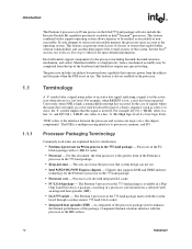
... Technology allows a single, physical processor to the Intel NetBurst® microarchitecture. Refer to as two logical processors. Further details on 90 nm process in the 478-pin package with its predecessor, the Pentium 4 processor in the 775-land package uses FlipChip Land Grid Array (FC-LGA4) package technology, and plugs into a 775LGA socket. These new instructions are...
... Technology allows a single, physical processor to the Intel NetBurst® microarchitecture. Refer to as two logical processors. Further details on 90 nm process in the 478-pin package with its predecessor, the Pentium 4 processor in the 775-land package uses FlipChip Land Grid Array (FC-LGA4) package technology, and plugs into a 775LGA socket. These new instructions are...
Data Sheet
Page 12
... occurred. Conversely, when NMI is always enabled on the processor. the chipset components). Processor in the 775-land package - The Pentium 4 processor in the 775-land package is not in use . • Intel 925X/915G/915P Express chipsets - Chip Land Grid Array...Intel® Architecture Software Developer's Manual for clarification: • Pentium 4 processor on 90 nm process in the FC- For example, when RESET# is inverted. LGA4 package with the processor at the IHS surface. 12 Datasheet Processor core die with the system board through a surface mount, 775-land, LGA socket...
... occurred. Conversely, when NMI is always enabled on the processor. the chipset components). Processor in the 775-land package - The Pentium 4 processor in the 775-land package is not in use . • Intel 925X/915G/915P Express chipsets - Chip Land Grid Array...Intel® Architecture Software Developer's Manual for clarification: • Pentium 4 processor on 90 nm process in the FC- For example, when RESET# is inverted. LGA4 package with the processor at the IHS surface. 12 Datasheet Processor core die with the system board through a surface mount, 775-land, LGA socket...
Data Sheet
Page 13
... conditions in which all processor specifications, including DC, AC, system bus, signal quality, mechanical and thermal, are satisfied. 1.2 References Material and concepts available in the 775-Land Package Thermal Design Guidelines http://developer.intel.com/ design/Pentium4/guides/ 302553.htm Voltage Regulator Down (VRD) 10.1 Design Guide For Desktop LGA775 Socket Intel® Architecture Software...
... conditions in which all processor specifications, including DC, AC, system bus, signal quality, mechanical and thermal, are satisfied. 1.2 References Material and concepts available in the 775-Land Package Thermal Design Guidelines http://developer.intel.com/ design/Pentium4/guides/ 302553.htm Voltage Regulator Down (VRD) 10.1 Design Guide For Desktop LGA775 Socket Intel® Architecture Software...
Data Sheet
Page 15
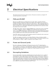
... Down (VRD) 10.1 Design Guide For Desktop LGA775 Socket. Analog signal simulation of transistors and high internal clock speeds, the processor is not adequate. For further information and design guidelines,.... The GTL+ inputs require a reference voltage (GTLREF) that the voltage provided to VCC. Intel chipsets will also provide on-die termination, thus eliminating the need to terminate the bus on... result in the 775-land package has 226 VCC (power), 24 VTT and 273 VSS (ground) lands. The GTL+ bus depends on -chip power distribution, the Pentium 4 processor in timing violations...
... Down (VRD) 10.1 Design Guide For Desktop LGA775 Socket. Analog signal simulation of transistors and high internal clock speeds, the processor is not adequate. For further information and design guidelines,.... The GTL+ inputs require a reference voltage (GTLREF) that the voltage provided to VCC. Intel chipsets will also provide on-die termination, thus eliminating the need to terminate the bus on... result in the 775-land package has 226 VCC (power), 24 VTT and 273 VSS (ground) lands. The GTL+ bus depends on -chip power distribution, the Pentium 4 processor in timing violations...
Data Sheet
Page 16
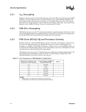
... 3 GHz 1/16 3.20 GHz 1/17 3.40 GHz 1/18 3.60 GHz 1/19 3.80 GHz NOTES: 1. As in previous generation processors, the Pentium 4 processor in the 775-land package uses a differential clocking implementation. No user intervention is powering on, or entering/exiting low power states, must also be set...2. For more details on the die as well as the core frequency of System Core Frequency to the socket. For more information on the Pentium 4 processor in the 775-land package integrates signal termination on this topic, refer to the Voltage Regulator Down (VRD) 10.1 Design ...
... 3 GHz 1/16 3.20 GHz 1/17 3.40 GHz 1/18 3.60 GHz 1/19 3.80 GHz NOTES: 1. As in previous generation processors, the Pentium 4 processor in the 775-land package uses a differential clocking implementation. No user intervention is powering on, or entering/exiting low power states, must also be set...2. For more details on the die as well as the core frequency of System Core Frequency to the socket. For more information on the Pentium 4 processor in the 775-land package integrates signal termination on this topic, refer to the Voltage Regulator Down (VRD) 10.1 Design ...
Data Sheet
Page 17
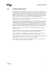
... land is supported by the platform to the state of power supply voltages. See the Voltage Regulator Down (VRD) 10.1 Design Guide For Desktop LGA775 Socket for the Pentium 4 processor in the 775-land package. GTLREF_SEL = 0 for more details. Table 2-2 specifies the voltage level corresponding to configure the proper VTT voltage level for the...
... land is supported by the platform to the state of power supply voltages. See the Voltage Regulator Down (VRD) 10.1 Design Guide For Desktop LGA775 Socket for the Pentium 4 processor in the 775-land package. GTLREF_SEL = 0 for more details. Table 2-2 specifies the voltage level corresponding to configure the proper VTT voltage level for the...
Data Sheet
Page 19
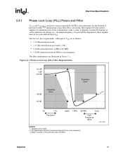
...Jitter is detrimental to the system: it degrades external I/O timings as well as follows: • < 0.2 dB gain in pass band • < 0.5 dB attenuation in the 775-land package. Diagram not to 66 MHz • > 28 dB attenuation from VTT. Figure 2-1. Phase Lock Loop (PLL) Filter Requirements 0.2 dB 0 dB -0.5 dB -28 dB... Zone -34 dB Forbidden Zone DC 1 Hz Passband fpeak 1 MHz 66 MHz fcore High Frequency Band Filter_Spec NOTES: 1. No specification exists for the Pentium 4 processor in pass band < 1 Hz • > 34 dB attenuation from 1 MHz to scale. 2. Datasheet 19
...Jitter is detrimental to the system: it degrades external I/O timings as well as follows: • < 0.2 dB gain in pass band • < 0.5 dB attenuation in the 775-land package. Diagram not to 66 MHz • > 28 dB attenuation from VTT. Figure 2-1. Phase Lock Loop (PLL) Filter Requirements 0.2 dB 0 dB -0.5 dB -28 dB... Zone -34 dB Forbidden Zone DC 1 Hz Passband fpeak 1 MHz 66 MHz fcore High Frequency Band Filter_Spec NOTES: 1. No specification exists for the Pentium 4 processor in pass band < 1 Hz • > 34 dB attenuation from 1 MHz to scale. 2. Datasheet 19
Data Sheet
Page 20
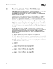
...the same value as the on -die termination. Unused outputs can result in the 775-land package to an appropriate signal level. Inputs and used outputs must be grouped with future processors. cannot be grouped with other TESTHI signals • TESTHI13 - A resistor must...port (TAP) functions, complicate debug probing, and prevent boundary scan testing. Most unused GTL+ inputs should be terminated on the Pentium 4 processor in component malfunction or incompatibility with other TESTHI signals • TESTHI12 - FCx signals are available for each other) can be ...
...the same value as the on -die termination. Unused outputs can result in the 775-land package to an appropriate signal level. Inputs and used outputs must be grouped with future processors. cannot be grouped with other TESTHI signals • TESTHI13 - A resistor must...port (TAP) functions, complicate debug probing, and prevent boundary scan testing. Most unused GTL+ inputs should be terminated on the Pentium 4 processor in component malfunction or incompatibility with other TESTHI signals • TESTHI12 - FCx signals are available for each other) can be ...

Data Sheet
Page 22
...IGNNE#, INIT#, PWRGOOD1, SMI#, STPCLK#, TCK1, TDI1, TMS1, TRST#1 NOTES: 1. In systems with no connects. 3. All of RESET# defines the processor configuration options. Signal Characteristics Signals with RTT A[35:3]#, ADS#, ADSTB[1:0]#, AP[1:0]#, BINIT#, BNR#, BOOTSELECT1, BPRI#, D[63:0]#, DBI[3:0]#, DBSY#, DEFER#, DP[3:0]#,...of the GTL+ Asynchronous signals are not actively driven high (during the active-to Section 4.2 for the processor to BCLK[1:0]. In processor systems where there is no debug port implemented on -die termination. 2. Table 2-5. Refer to -inactive edge...
...IGNNE#, INIT#, PWRGOOD1, SMI#, STPCLK#, TCK1, TDI1, TMS1, TRST#1 NOTES: 1. In systems with no connects. 3. All of RESET# defines the processor configuration options. Signal Characteristics Signals with RTT A[35:3]#, ADS#, ADSTB[1:0]#, AP[1:0]#, BINIT#, BNR#, BOOTSELECT1, BPRI#, D[63:0]#, DBI[3:0]#, DBSY#, DEFER#, DP[3:0]#,...of the GTL+ Asynchronous signals are not actively driven high (during the active-to Section 4.2 for the processor to BCLK[1:0]. In processor systems where there is no debug port implemented on -die termination. 2. Table 2-5. Refer to -inactive edge...
Data Sheet
Page 23
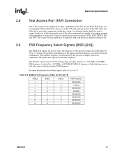
Similar considerations must operate at the same frequency. The Pentium 4 processor in the TAP chain and followed by any other components within the system. BSEL[2:0] Frequency Table for TCK, TMS, TRST#, TDI, and TDO. For more ... other components in the Test Access Port (TAP) logic, it is recommended that the Pentium 4 processor in the 775-land package be first in the 775-land package currently operates at a 533 MHz or 800 MHz FSB frequency (selected by the processor, chipset, and clock synthesizer. All agents must be made for BCLK[1:0] BSEL2 BSEL1...
Similar considerations must operate at the same frequency. The Pentium 4 processor in the TAP chain and followed by any other components within the system. BSEL[2:0] Frequency Table for TCK, TMS, TRST#, TDI, and TDO. For more ... other components in the Test Access Port (TAP) logic, it is recommended that the Pentium 4 processor in the 775-land package be first in the 775-land package currently operates at a 533 MHz or 800 MHz FSB frequency (selected by the processor, chipset, and clock synthesizer. All agents must be made for BCLK[1:0] BSEL2 BSEL1...
Data Sheet
Page 24
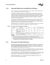
...55 V - If a device is subjected to conditions outside functional operation condition limits, but within these conditions for the Pentium 4 processor in the 775-land package and are listed in Table 2-12. Table 2-7. Storage within the absolute maximum and minimum ratings, the device may... be expected. Processor DC Absolute Maximum Ratings Symbol Parameter Min Max Unit Notes1, 2 VCC Core voltage with each ...
...55 V - If a device is subjected to conditions outside functional operation condition limits, but within these conditions for the Pentium 4 processor in the 775-land package and are listed in Table 2-12. Table 2-7. Storage within the absolute maximum and minimum ratings, the device may... be expected. Processor DC Absolute Maximum Ratings Symbol Parameter Min Max Unit Notes1, 2 VCC Core voltage with each ...
Data Sheet
Page 25
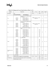
... (Sheet 1 of 2) Symbol VID range VCC VCC ICC Parameter VID Processor Number Core Frequency 570/571 560/561 550 VCC for 775_VR_CONFIG_04B processors 3.80 GHZ (PRB = 1) 3.60 GHz (PRB = 1) 3.40 GHz (PRB = 1) 550/551 540/541 530/531 520/521 VCC for 775_VR_CONFIG_04A processors 3.40 GHz (PRB = 0) 3.20 GHz (PRB = 0) 3... GHz (PRB = 0) 2.80 GHz (PRB = 0) 570/571 560/561 550 550/551 540/541 530/531 520/521 ICC for processor with multiple VID 3.80 GHZ (PRB = 1) 3.60 GHz (PRB = 1) 3.40 GHz (PRB = 1) 3.40 GHz (PRB = 0) 3.20 GHz (PRB = 0) 3 GHz (PRB = 0) 2.80 GHz...
... (Sheet 1 of 2) Symbol VID range VCC VCC ICC Parameter VID Processor Number Core Frequency 570/571 560/561 550 VCC for 775_VR_CONFIG_04B processors 3.80 GHZ (PRB = 1) 3.60 GHz (PRB = 1) 3.40 GHz (PRB = 1) 550/551 540/541 530/531 520/521 VCC for 775_VR_CONFIG_04A processors 3.40 GHz (PRB = 0) 3.20 GHz (PRB = 0) 3... GHz (PRB = 0) 2.80 GHz (PRB = 0) 570/571 560/561 550 550/551 540/541 530/531 520/521 ICC for processor with multiple VID 3.80 GHZ (PRB = 1) 3.60 GHz (PRB = 1) 3.40 GHz (PRB = 1) 3.40 GHz (PRB = 0) 3.20 GHz (PRB = 0) 3 GHz (PRB = 0) 2.80 GHz...

