
Data Sheet
Page 2
... latest specifications and before placing your PC manufacturer on request. ∆ Intel processor numbers are not a measure of any time, without an Intel EM64T-enabled BIOS. Performance will vary depending on your system delivers Execute Disable Bit functionality. INTEL PRODUCTS ARE NOT INTENDED FOR USE IN MEDICAL, LIFE SAVING, OR LIFE SUSTAINING APPLICATIONS. Check with an Intel® Pentium® 4 processor supporting Hyper-Threading...
... latest specifications and before placing your PC manufacturer on request. ∆ Intel processor numbers are not a measure of any time, without an Intel EM64T-enabled BIOS. Performance will vary depending on your system delivers Execute Disable Bit functionality. INTEL PRODUCTS ARE NOT INTENDED FOR USE IN MEDICAL, LIFE SAVING, OR LIFE SUSTAINING APPLICATIONS. Check with an Intel® Pentium® 4 processor supporting Hyper-Threading...
Data Sheet
Page 3
... Minimum Ratings 24 2.11 Processor DC Specifications 24 2.12 VCC Overshoot Specification 33 2.12.1 Die Voltage Validation 33 2.13 GTL+ FSB Specifications...34 3 Package Mechanical Specifications 35 3.1 Package Mechanical Drawing 35 3.2 Processor Component Keep-Out Zones 39 3.3 Package Loading Specifications 39 3.4 Package Handling Guidelines 39 3.5 Package Insertion Specifications 40 3.6 Processor Mass Specification 40 3.7 Processor Materials ...40 3.8 Processor Markings ...40 3.9 Processor Land Coordinates 41 4 Land...
... Minimum Ratings 24 2.11 Processor DC Specifications 24 2.12 VCC Overshoot Specification 33 2.12.1 Die Voltage Validation 33 2.13 GTL+ FSB Specifications...34 3 Package Mechanical Specifications 35 3.1 Package Mechanical Drawing 35 3.2 Processor Component Keep-Out Zones 39 3.3 Package Loading Specifications 39 3.4 Package Handling Guidelines 39 3.5 Package Insertion Specifications 40 3.6 Processor Mass Specification 40 3.7 Processor Materials ...40 3.8 Processor Markings ...40 3.9 Processor Land Coordinates 41 4 Land...
Data Sheet
Page 6
... 3-3 Processor Materials ...40 4-1 Alphabetical Land Assignments 46 4-2 Numerical Land Assignment...56 4-3 Signal Description...66 5-1 Processor Thermal Specifications 76 5-2 Thermal Profile for Processors with PRB = 1 77 5-3 Thermal Profile for Processors with PRB = 0 78 5-4 Thermal Diode Parameters ...83 5-5 Thermal Diode Interface ...83 6-1 Power-On Configuration Option Signals 85 7-1 Fan Heatsink Power and Signal Specifications 92 7-2 Fan Heatsink Power and Signal Specifications 96 § 6 Datasheet
... 3-3 Processor Materials ...40 4-1 Alphabetical Land Assignments 46 4-2 Numerical Land Assignment...56 4-3 Signal Description...66 5-1 Processor Thermal Specifications 76 5-2 Thermal Profile for Processors with PRB = 1 77 5-3 Thermal Profile for Processors with PRB = 0 78 5-4 Thermal Diode Parameters ...83 5-5 Thermal Diode Interface ...83 6-1 Power-On Configuration Option Signals 85 7-1 Fan Heatsink Power and Signal Specifications 92 7-2 Fan Heatsink Power and Signal Specifications 96 § 6 Datasheet

Data Sheet
Page 7
... specifications for processor number 550 with PRB = 0 • Added support for Execute Disable Bit capability • Added Icc Enhanced Auto Halt specifications • Added support for Thermal Monitor 2 • Added specifications for processor number 570 with PRB = 1 • Added specifications for processor numbers 571, 561, 551, 541, 531, and 521. • Modified Table 2-3, "FSB Signal Groups". • Added Note 5 to Table 2-18. • Updated Figure...
... specifications for processor number 550 with PRB = 0 • Added support for Execute Disable Bit capability • Added Icc Enhanced Auto Halt specifications • Added support for Thermal Monitor 2 • Added specifications for processor number 570 with PRB = 1 • Added specifications for processor numbers 571, 561, 551, 541, 531, and 521. • Modified Table 2-3, "FSB Signal Groups". • Added Note 5 to Table 2-18. • Updated Figure...

Data Sheet
Page 9
... 2.80 GHz • Supports Hyper-Threading Technology1 (HT Technology) for all frequencies with 800 MHz front side bus (FSB) • Intel® Pentium® 4 processors 571, 561, 551, 541, 531, and 521 support Intel® Extended Memory 64 Technology (EM64T)Φ • Supports Execute Disable Bit capability • Binary compatible with 8-way associativity and Error Correcting Code (ECC) • 144 Streaming SIMD Extensions 2 (SSE2) instructions...
... 2.80 GHz • Supports Hyper-Threading Technology1 (HT Technology) for all frequencies with 800 MHz front side bus (FSB) • Intel® Pentium® 4 processors 571, 561, 551, 541, 531, and 521 support Intel® Extended Memory 64 Technology (EM64T)Φ • Supports Execute Disable Bit capability • Binary compatible with 8-way associativity and Error Correcting Code (ECC) • 144 Streaming SIMD Extensions 2 (SSE2) instructions...

Data Sheet
Page 11
... bus clock (4X data transfer rate, as platforms with the Pentium 4 processor in the 775-land package and SSE3 become available in the market place. These new instructions are 13 new instructions that further extend the capabilities of these new instructions as in AGP 4X). The processor's Intel NetBurst microarchitecture FSB uses a split-transaction, deferred reply protocol like its own set of compatibility with IA-32...
... bus clock (4X data transfer rate, as platforms with the Pentium 4 processor in the 775-land package and SSE3 become available in the market place. These new instructions are 13 new instructions that further extend the capabilities of these new instructions as in AGP 4X). The processor's Intel NetBurst microarchitecture FSB uses a split-transaction, deferred reply protocol like its own set of compatibility with IA-32...
Data Sheet
Page 12
... system board through a surface mount, 775-land, LGA socket. • Integrated heat spreader (IHS) -A component of the processor package used terms are explained here for the Pentium 4 processor in a Flip- Intel will also include the Execute Disable Bit capability previously available in the 775-land package - Processor Packaging Terminology Commonly used to the operating system. Chipsets that supports DDR and DDR2 memory technology for...
... system board through a surface mount, 775-land, LGA socket. • Integrated heat spreader (IHS) -A component of the processor package used terms are explained here for the Pentium 4 processor in a Flip- Intel will also include the Execute Disable Bit capability previously available in the 775-land package - Processor Packaging Terminology Commonly used to the operating system. Chipsets that supports DDR and DDR2 memory technology for...
Data Sheet
Page 15
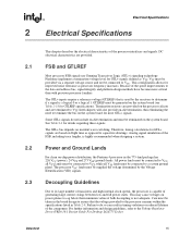
...its large number of transistors and high internal clock speeds, the processor is capable of the FSB, including trace lengths, is highly recommended when designing a system. Decoupling Guidelines Due to determine if a signal is not adequate. FSB and GTLREF Most processor FSB signals use Gunning Transceiver... as VTT. This may cause voltages on flight time as processor frequency increases. Intel chipsets will also provide on-die termination, thus eliminating the need to the processor remains within the specifications listed in the 775-land package has 226 VCC (power), 24 VTT and 273...
...its large number of transistors and high internal clock speeds, the processor is capable of the FSB, including trace lengths, is highly recommended when designing a system. Decoupling Guidelines Due to determine if a signal is not adequate. FSB and GTLREF Most processor FSB signals use Gunning Transceiver... as VTT. This may cause voltages on flight time as processor frequency increases. Intel chipsets will also provide on-die termination, thus eliminating the need to the processor remains within the specifications listed in the 775-land package has 226 VCC (power), 24 VTT and 273...
Data Sheet
Page 16
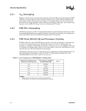
.../CK410M Clock Synthesizer/Driver Specification. For more details on the die as well as the core frequency of System Core Frequency to the socket. The processor bus ratio multiplier will automatically run at or below the rated frequency. 2. Core Frequency to FSB Multiplier Configuration Multiplication of the processor. As in previous generation processors, the Pentium 4 processor in the 775-land package uses a differential clocking...
.../CK410M Clock Synthesizer/Driver Specification. For more details on the die as well as the core frequency of System Core Frequency to the socket. The processor bus ratio multiplier will automatically run at or below the rated frequency. 2. Core Frequency to FSB Multiplier Configuration Multiplication of the processor. As in previous generation processors, the Pentium 4 processor in the 775-land package uses a differential clocking...
Data Sheet
Page 24
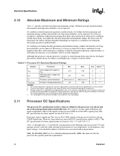
... conditions for the Pentium 4 processor in the 775-land package and are listed in the GTL+ signal group. If a device is applicable to the processor case temperature specifications. 4. VTT FSB termination voltage with its reliability will be satisfied. 2. For functional operation, all notes associated with respect to the processor used low-voltage CMOS buffer types. Electrical Specifications 2.10 Absolute Maximum...
... conditions for the Pentium 4 processor in the 775-land package and are listed in the GTL+ signal group. If a device is applicable to the processor case temperature specifications. 4. VTT FSB termination voltage with its reliability will be satisfied. 2. For functional operation, all notes associated with respect to the processor used low-voltage CMOS buffer types. Electrical Specifications 2.10 Absolute Maximum...
Data Sheet
Page 25
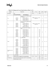
Voltage and Current Specifications (Sheet 1 of 2) Symbol VID range VCC VCC ICC Parameter VID Processor Number Core Frequency 570/571 560/561 550 VCC for 775_VR_CONFIG_04B processors 3.80 GHZ (PRB = 1) 3.60 GHz (PRB = 1) 3.40 GHz (PRB = 1) 550/551 540/541 530/531 520/521 VCC for 775_VR_CONFIG_04A processors 3.40 GHz (PRB = 0) 3.20 GHz (PRB = 0) 3 GHz (PRB = 0) 2.80 GHz (PRB = 0) 570/571 560/561 550...
Voltage and Current Specifications (Sheet 1 of 2) Symbol VID range VCC VCC ICC Parameter VID Processor Number Core Frequency 570/571 560/561 550 VCC for 775_VR_CONFIG_04B processors 3.80 GHZ (PRB = 1) 3.60 GHz (PRB = 1) 3.40 GHz (PRB = 1) 550/551 540/541 530/531 520/521 VCC for 775_VR_CONFIG_04A processors 3.40 GHz (PRB = 0) 3.20 GHz (PRB = 0) 3 GHz (PRB = 0) 2.80 GHz (PRB = 0) 570/571 560/561 550...
Data Sheet
Page 31
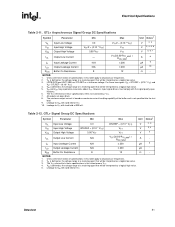
...processor frequencies. 2. Unless otherwise noted, all specifications in this table apply to all processor frequencies. 2. LINT0/INTR and LINT1/NMI use GTLREF as the voltage range at VTT. 10. However, input signal drivers...that will be interpreted as a logical low value. 3. GTL+ Signal Group DC Specifications Symbol Parameter Min Max Unit VIL Input Low Voltage 0.0 GTLREF - (0.10 * VTT) V VIH ... 4 3 - 5 - - The VTT referred to in these specifications refers to VSS with the signal quality spec- For these two signals VIH = GTLREF + (0.10 * VTT) and VIL= GTLREF - ...
...processor frequencies. 2. Unless otherwise noted, all specifications in this table apply to all processor frequencies. 2. LINT0/INTR and LINT1/NMI use GTLREF as the voltage range at VTT. 10. However, input signal drivers...that will be interpreted as a logical low value. 3. GTL+ Signal Group DC Specifications Symbol Parameter Min Max Unit VIL Input Low Voltage 0.0 GTLREF - (0.10 * VTT) V VIH ... 4 3 - 5 - - The VTT referred to in these specifications refers to VSS with the signal quality spec- For these two signals VIH = GTLREF + (0.10 * VTT) and VIL= GTLREF - ...
Data Sheet
Page 32
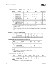
... V. Leakage to all processor frequencies. 2. BSEL [2:0] and VID[5:0] DC Specifications Symbol Parameter Max Unit Notes1, 2 RON (BSEL) Buffer On Resistance 60 Ω - Unless otherwise noted, all specifications in this table apply to all processor frequencies. 2. ILO Output ...threshold voltage 200 350 mV 3 0.5 * (VTT + VHYS_MIN) 0.5 * (VTT + VHYS_MAX) V 4 VT- PWRGOOD and TAP Signal Group DC Specifications Symbol Parameter Min Max Unit Notes1, 2 VHYS VT+ Input Hysteresis Input low to low threshold voltage 0.5 * (VTT - VTT 45 ± 200 ± 200 V ...
... V. Leakage to all processor frequencies. 2. BSEL [2:0] and VID[5:0] DC Specifications Symbol Parameter Max Unit Notes1, 2 RON (BSEL) Buffer On Resistance 60 Ω - Unless otherwise noted, all specifications in this table apply to all processor frequencies. 2. ILO Output ...threshold voltage 200 350 mV 3 0.5 * (VTT + VHYS_MIN) 0.5 * (VTT + VHYS_MAX) V 4 VT- PWRGOOD and TAP Signal Group DC Specifications Symbol Parameter Min Max Unit Notes1, 2 VHYS VT+ Input Hysteresis Input low to low threshold voltage 0.5 * (VTT - VTT 45 ± 200 ± 200 V ...
Data Sheet
Page 34
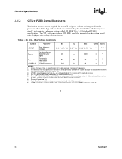
... your Intel representative for this table apply to VSS. § 34 Datasheet COMP ...specifications. use a pull-up resistor of 100 Ω and a pull-down resistor of the GTL+ output driver. 8. Unless otherwise noted, all specifications in this specification have been stated generically to enable the system designer to VTT. 7. These pull-ups are to all processor frequencies. 2. The The IVnTteTl®re9fe1r5reGd/9t1o5inGVth/e9s1e5Pspaencdifi9c1a0tiGonLsEisxpthreesisnscthaipnstaent epolautsfoVrmTTs. Electrical Specifications 2.13 GTL+ FSB Specifications...
... your Intel representative for this table apply to VSS. § 34 Datasheet COMP ...specifications. use a pull-up resistor of 100 Ω and a pull-down resistor of the GTL+ output driver. 8. Unless otherwise noted, all specifications in this specification have been stated generically to enable the system designer to VTT. 7. These pull-ups are to all processor frequencies. 2. The The IVnTteTl®re9fe1r5reGd/9t1o5inGVth/e9s1e5Pspaencdifi9c1a0tiGonLsEisxpthreesisnscthaipnstaent epolautsfoVrmTTs. Electrical Specifications 2.13 GTL+ FSB Specifications...
Data Sheet
Page 69
... support of IERR# is asserted by system core logic. For additional information on the Intel 387 coprocessor, and is used to indicate that the processor has a pending break event waiting for GTL+ input signals. Assertion of the feature and enable/disable information, refer to an external error signal (e.g., NMI) by the data driver on each data transfer, indicating valid data...
... support of IERR# is asserted by system core logic. For additional information on the Intel 387 coprocessor, and is used to indicate that the processor has a pending break event waiting for GTL+ input signals. Assertion of the feature and enable/disable information, refer to an external error signal (e.g., NMI) by the data driver on each data transfer, indicating valid data...

Data Sheet
Page 70
...# has no effect when the NE bit in the 775-land package. ITP_CLK[1:0] are defined by the following an Input/Output write instruction, it observes an error in the system. Signal Description (Sheet 5 of RESET#, then the processor executes its internal caches or floating-point registers. MCERR# assertion conditions are used as NMI/INTR or LINT[1:0]. When...
...# has no effect when the NE bit in the 775-land package. ITP_CLK[1:0] are defined by the following an Input/Output write instruction, it observes an error in the system. Signal Description (Sheet 5 of RESET#, then the processor executes its internal caches or floating-point registers. MCERR# assertion conditions are used as NMI/INTR or LINT[1:0]. When...

Data Sheet
Page 80
... a noticeable performance loss, and in some cases may result in order to support Thermal Monitor 2. The duty cycle for the TCC, when activated by issuing a new VID code to the new frequency. When the enhanced TCC is factory configured and cannot be one VID table entry (i.e., 12.5 mV steps). Thermal Monitor 2 The Pentium 4 processor in the 775-Land Package...
... a noticeable performance loss, and in some cases may result in order to support Thermal Monitor 2. The duty cycle for the TCC, when activated by issuing a new VID code to the new frequency. When the enhanced TCC is factory configured and cannot be one VID table entry (i.e., 12.5 mV steps). Thermal Monitor 2 The Pentium 4 processor in the 775-Land Package...
Data Sheet
Page 82
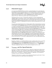
...) 10.1 Design Guide for Desktop Socket 775 for further details and documentation. 82 Datasheet Thermal Specifications and Design Considerations 5.2.4 5.2.5 5.2.6 PROCHOT# Signal An external signal, PROCHOT# (processor hot), is a temperature specification based on a temperature reading from an external source to be maintained at its Thermal Design Power. TCONTROL and Fan Speed Reduction TCONTROL is asserted when the processor die temperature has reached its...
...) 10.1 Design Guide for Desktop Socket 775 for further details and documentation. 82 Datasheet Thermal Specifications and Design Considerations 5.2.4 5.2.5 5.2.6 PROCHOT# Signal An external signal, PROCHOT# (processor hot), is a temperature specification based on a temperature reading from an external source to be maintained at its Thermal Design Power. TCONTROL and Fan Speed Reduction TCONTROL is asserted when the processor die temperature has reached its...
Data Sheet
Page 93
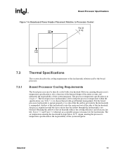
... of the fan heatsink solution used by the boxed processor. For the boxed processor fan heatsink to operate properly, it is unimpeded. Datasheet 93 The air temperature entering the fan should be directly cooled with a fan heatsink. Blocking the airflow to the fan heatsink is critical that the airflow provided to the fan heatsink reduces the cooling efficiency and decreases fan life. Baseboard Power Header Placement Relative to Processor Socket R4...
... of the fan heatsink solution used by the boxed processor. For the boxed processor fan heatsink to operate properly, it is unimpeded. Datasheet 93 The air temperature entering the fan should be directly cooled with a fan heatsink. Blocking the airflow to the fan heatsink is critical that the airflow provided to the fan heatsink reduces the cooling efficiency and decreases fan life. Baseboard Power Header Placement Relative to Processor Socket R4...
Data Sheet
Page 95
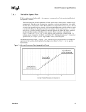
... then lower set point. Figure 7-9. Boxed Processor Fan Heatsink Set Points Increasing Fan Speed & Noise Higher Set Point Highest Noise Level Lower Set Point Lowest Noise Level X Y Z Internal Chassis Temperature (Degrees C) Datasheet 95 Boxed Processor Specifications 7.3.2 Variable Speed Fan If the boxed processor fan heatsink 4-pin connector is connected to a 3-pin motherboard header it will operate as follows: The boxed processor fan will rise linearly with the internal temperature until the higher set point is...
... then lower set point. Figure 7-9. Boxed Processor Fan Heatsink Set Points Increasing Fan Speed & Noise Higher Set Point Highest Noise Level Lower Set Point Lowest Noise Level X Y Z Internal Chassis Temperature (Degrees C) Datasheet 95 Boxed Processor Specifications 7.3.2 Variable Speed Fan If the boxed processor fan heatsink 4-pin connector is connected to a 3-pin motherboard header it will operate as follows: The boxed processor fan will rise linearly with the internal temperature until the higher set point is...


