

English Manual
Page 2
... the telephone number on the front cover of the warning decals. TABLE OF CONTENTS WARNING DECAL PLACEMENT 2 IMPORTANT PRECAUTIONS 3 BEFORE YOU BEGIN 5 ASSEMBLY 6 OPERATION AND ADJUSTMENT 13 HOW TO FOLD AND MOVE THE TREADMILL 19 TROUBLESHOOTING 20 EXERCISE GUIDELINES 22 PART LIST 23 EXPLODED DRAWING 24 ORDERING REPLACEMENT PARTS Back Cover LIMITED WARRANTY Back Cover WARNING DECAL PLACEMENT This drawing shows the locations of this manual and request a free replacement decal. Apply...
... the telephone number on the front cover of the warning decals. TABLE OF CONTENTS WARNING DECAL PLACEMENT 2 IMPORTANT PRECAUTIONS 3 BEFORE YOU BEGIN 5 ASSEMBLY 6 OPERATION AND ADJUSTMENT 13 HOW TO FOLD AND MOVE THE TREADMILL 19 TROUBLESHOOTING 20 EXERCISE GUIDELINES 22 PART LIST 23 EXPLODED DRAWING 24 ORDERING REPLACEMENT PARTS Back Cover LIMITED WARRANTY Back Cover WARNING DECAL PLACEMENT This drawing shows the locations of this manual and request a free replacement decal. Apply...

English Manual
Page 3
... oxygen is not working properly. (See TROUBLESHOOTING on your treadmill. Athletic support clothes are adequately informed of all warnings and precautions. 3. When connecting the power cord (see HOW TO TURN ON THE POWER on the same circuit. Never start the treadmill while you are used by or through the use a properly functioning surge suppressor could become caught in this manual and order part number 146148, or see...
... oxygen is not working properly. (See TROUBLESHOOTING on your treadmill. Athletic support clothes are adequately informed of all warnings and precautions. 3. When connecting the power cord (see HOW TO TURN ON THE POWER on the same circuit. Never start the treadmill while you are used by or through the use a properly functioning surge suppressor could become caught in this manual and order part number 146148, or see...

English Manual
Page 4
... power switch.) 21. DANGER: 27. Over exercising may result in speed. 20. When folding or moving the treadmill, make sure that the storage latch is intended for the location of the treadmill by an authorized service representative. Inspect and properly tighten all parts of high speeds. If you feel faint or if you experience pain while exercising, stop immediately and cool down. SAVE THESE INSTRUCTIONS 4 The treadmill is not in -home use...
... power switch.) 21. DANGER: 27. Over exercising may result in speed. 20. When folding or moving the treadmill, make sure that the storage latch is intended for the location of the treadmill by an authorized service representative. Inspect and properly tighten all parts of high speeds. If you feel faint or if you experience pain while exercising, stop immediately and cool down. SAVE THESE INSTRUCTIONS 4 The treadmill is not in -home use...

English Manual
Page 5
..., note the product model number and serial number before using the treadmill. Accessory Tray Handrail Storage Latch Walking Belt Foot Rail Idler Roller Adjustment Bolts Console Pulse Sensor Key/Clip Hood Power Switch Power Cord Wheel Platform Cushion 5 The 20.0 VT treadmill offers a selection of features designed to make your benefit, read - And when you for selecting the new IMAGE® 20.0 VT treadmill. ing this manual, please see the front cover of this manual. Before reading further, please review the drawing below...
..., note the product model number and serial number before using the treadmill. Accessory Tray Handrail Storage Latch Walking Belt Foot Rail Idler Roller Adjustment Bolts Console Pulse Sensor Key/Clip Hood Power Switch Power Cord Wheel Platform Cushion 5 The 20.0 VT treadmill offers a selection of features designed to make your benefit, read - And when you for selecting the new IMAGE® 20.0 VT treadmill. ing this manual, please see the front cover of this manual. Before reading further, please review the drawing below...

English Manual
Page 6
... damaging parts, do not use power tools for assembly. Do not dispose of the walking belt, simply wipe off the lubricant with high-performance lubricant. If there is lubricant on top of the packing materials until assembly is the key number of the part, from the PART LIST near the end of this manual. Note: Some small parts may be transferred to the top of the treadmill walking belt is...
... damaging parts, do not use power tools for assembly. Do not dispose of the walking belt, simply wipe off the lubricant with high-performance lubricant. If there is lubricant on top of the packing materials until assembly is the key number of the part, from the PART LIST near the end of this manual. Note: Some small parts may be transferred to the top of the treadmill walking belt is...

English Manual
Page 9
... the inset drawing. Insert the included wire tie through the indicated small hole in step 5. do not fully tighten the Patch Bolt yet. 53 Top View 1 14 11 9 23 53 9 14 1 11 23 7. Set the Console Assembly (91) face down on the Console Assembly (91). Hold the Frame Spacer (11) between the Left Upright (53) and the Lift Frame (23...
... the inset drawing. Insert the included wire tie through the indicated small hole in step 5. do not fully tighten the Patch Bolt yet. 53 Top View 1 14 11 9 23 53 9 14 1 11 23 7. Set the Console Assembly (91) face down on the Console Assembly (91). Hold the Frame Spacer (11) between the Left Upright (53) and the Lift Frame (23...

English Manual
Page 11
Attach the ground wire on the Right 10 Upright (54) and the Left Upright (53). 10. With the help of a second person, carefully lower the Left Upright (not shown) and the Right Upright (54) to the indicated hole in the Base (52) with four M8 Star Washers (5) into the Uprights. Then, firmly tighten all four Bolts. 85 58 53 91 8 5 54 85 11. Start four M8 x 15mm Bolts (8) with an M4 x 10mm Ground Screw (84). 11 52 Hole Ground Wire 54 84 39 11 Set the Console Assembly (91) on the Wire Harness (39) to the floor.
Attach the ground wire on the Right 10 Upright (54) and the Left Upright (53). 10. With the help of a second person, carefully lower the Left Upright (not shown) and the Right Upright (54) to the indicated hole in the Base (52) with four M8 Star Washers (5) into the Uprights. Then, firmly tighten all four Bolts. 85 58 53 91 8 5 54 85 11. Start four M8 x 15mm Bolts (8) with an M4 x 10mm Ground Screw (84). 11 52 Hole Ground Wire 54 84 39 11 Set the Console Assembly (91) on the Wire Harness (39) to the floor.

English Manual
Page 12
... is used to adjust the walking belt (see page 21). Locate the Latch Pin Assembly (24). One of them . Then, tighten the knob onto the pin. 13 Knob 24 48 13 Large Hole 53 Spring Collar Pin 14. Position the Uprights (53, 54) so that the collar and the spring are on the pin. (Note: If there are properly tightened before you use the treadmill. Raise the Uprights (53...
... is used to adjust the walking belt (see page 21). Locate the Latch Pin Assembly (24). One of them . Then, tighten the knob onto the pin. 13 Knob 24 48 13 Large Hole 53 Spring Collar Pin 14. Position the Uprights (53, 54) so that the collar and the spring are on the pin. (Note: If there are properly tightened before you use the treadmill. Raise the Uprights (53...

English Manual
Page 13
... will not fit the outlet, have a UL suppressed voltage rating of 400 volts or less and a minimum surge dissipation of 450 joules. A temporary adapter may be a monitoring light on a nominal 120-volt circuit (see drawing 1 at the right). There must have a proper outlet in your treadmill (see drawing 1). OPERATION AND ADJUSTMENT THE PRE-LUBRICATED WALKING BELT Your treadmill features a walking belt coated...
... will not fit the outlet, have a UL suppressed voltage rating of 400 volts or less and a minimum surge dissipation of 450 joules. A temporary adapter may be a monitoring light on a nominal 120-volt circuit (see drawing 1 at the right). There must have a proper outlet in your treadmill (see drawing 1). OPERATION AND ADJUSTMENT THE PRE-LUBRICATED WALKING BELT Your treadmill features a walking belt coated...
English Manual
Page 14
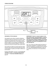
... the manual mode of the console, you exercise, the displays will provide continuous exercise feedback. You can display speed and distance in this manual refer to miles. To use the manual mode, see page 21). For simplicity, all instructions in either miles or kilometers. CONSOLE DIAGRAM Key Clip FEATURES OF THE CONSOLE The treadmill console offers a selection of features designed to make your heart rate using the treadmill. Each workout controls the speed and incline of the walking belt, and center the walking belt...
... the manual mode of the console, you exercise, the displays will provide continuous exercise feedback. You can display speed and distance in this manual refer to miles. To use the manual mode, see page 21). For simplicity, all instructions in either miles or kilometers. CONSOLE DIAGRAM Key Clip FEATURES OF THE CONSOLE The treadmill console offers a selection of features designed to make your heart rate using the treadmill. Each workout controls the speed and incline of the walking belt, and center the walking belt...

English Manual
Page 15
... selected incline setting. 15 Reset IMPORTANT: The console features a display demo mode, designed to be used if the treadmill is inserted, the manual mode will be pulled from the console, adjust the position of the buttons, the speed setting will begin to flash in the power cord and press the power switch into the reset position, the demo mode is not pulled from the console, causing the walking belt to slow to a stop the walking belt, press the Stop button. if the key is turned...
... selected incline setting. 15 Reset IMPORTANT: The console features a display demo mode, designed to be used if the treadmill is inserted, the manual mode will be pulled from the console, adjust the position of the buttons, the speed setting will begin to flash in the power cord and press the power switch into the reset position, the demo mode is not pulled from the console, causing the walking belt to slow to a stop the walking belt, press the Stop button. if the key is turned...

English Manual
Page 16
... a preset workout is selected, the display will show the speed of the walking belt and the approximate number of the elapsed time. Press the Display Mode button repeatedly until the upper display shows the information that your hands. To reset the displays, press the Stop button, remove the key, and then reinsert the key. 7. The incline must be at the right). Follow your heart rate if desired. Contacts The lower right display-The lower right display can...
... a preset workout is selected, the display will show the speed of the walking belt and the approximate number of the elapsed time. Press the Display Mode button repeatedly until the upper display shows the information that your hands. To reset the displays, press the Stop button, remove the key, and then reinsert the key. 7. The incline must be at the right). Follow your heart rate if desired. Contacts The lower right display-The lower right display can...

English Manual
Page 17
... incline setting are finished exercising, remove the key from the console. Start the workout. HOW TO USE A PRESET WORKOUT 1. The walking belt will begin walking. See HOW TO TURN ON THE POWER on the console; Then, the duration of the Select buttons below the profiles on page 15. 2. One speed setting and one of the workout will sound. Hold the handrails and begin to move at any time, press the Stop button. To stop . The walking belt...
... incline setting are finished exercising, remove the key from the console. Start the workout. HOW TO USE A PRESET WORKOUT 1. The walking belt will begin walking. See HOW TO TURN ON THE POWER on the console; Then, the duration of the Select buttons below the profiles on page 15. 2. One speed setting and one of the workout will sound. Hold the handrails and begin to move at any time, press the Stop button. To stop . The walking belt...
English Manual
Page 18
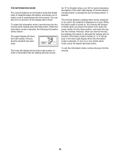
... "M" for the console. THE INFORMATION MODE The console features an information mode that the treadmill has been used if the treadmill is displayed in the lower right display. Press the Speed increase button to select a unit of miles or kilometers that the walking belt has moved. To exit the information mode, remove the key from the console. 18 You can also turn off the demo mode, press the Speed decrease button. The lower left display will show the total number of measurement for...
... "M" for the console. THE INFORMATION MODE The console features an information mode that the treadmill has been used if the treadmill is displayed in the lower right display. Press the Speed increase button to select a unit of miles or kilometers that the walking belt has moved. To exit the information mode, remove the key from the console. 18 You can also turn off the demo mode, press the Speed decrease button. The lower left display will show the total number of measurement for...

English Manual
Page 19
... latch pin. 2 Engaged Latch Knob Latch Pin Latch Plate To protect the floor or carpet, place a mat under the treadmill. See drawing 1 at the left . Then, remove the key and unplug the power cord. Hold the metal frame firmly in temperatures above 85° F (30° C). 2. Bend your legs and keep your right hand as shown. Moving the treadmill may require two people. 1. Pull the latch knob...
... latch pin. 2 Engaged Latch Knob Latch Pin Latch Plate To protect the floor or carpet, place a mat under the treadmill. See drawing 1 at the left . Then, remove the key and unplug the power cord. Hold the metal frame firmly in temperatures above 85° F (30° C). 2. Bend your legs and keep your right hand as shown. Moving the treadmill may require two people. 1. Pull the latch knob...

English Manual
Page 20
... suppressor is needed, see the front cover of this manual. Reinsert the key into the console. TROUBLESHOOTING Most treadmill problems can be solved by following the steps below. IMPORTANT: The treadmill is aligned with GFCI-equipped outlets. Check the power switch (see page 13). Then, carefully remove the Motor Hood (65). 65 20 25 Locate the Reed Switch (89) and the Magnet (62) on page 13. Turn the Pulley until the...
... suppressor is needed, see the front cover of this manual. Reinsert the key into the console. TROUBLESHOOTING Most treadmill problems can be solved by following the steps below. IMPORTANT: The treadmill is aligned with GFCI-equipped outlets. Check the power switch (see page 13). Then, carefully remove the Motor Hood (65). 65 20 25 Locate the Reed Switch (89) and the Magnet (62) on page 13. Turn the Pulley until the...

English Manual
Page 21
... front cover of the walking belt 2 to 3 in a store. Remove the key and UNPLUG THE POWER CORD. When the walking belt is correctly tightened, you should be used if the treadmill is off the demo mode. 21 PROBLEM: The incline of the Incline buttons. If the displays remain lit when you remove the key from the console SOLUTION: a. Be careful not to the left idler roller bolt counterclockwise 1/2 of a turn . To turn off -center or slips when walked...
... front cover of the walking belt 2 to 3 in a store. Remove the key and UNPLUG THE POWER CORD. When the walking belt is correctly tightened, you should be used if the treadmill is off the demo mode. 21 PROBLEM: The incline of the Incline buttons. If the displays remain lit when you remove the key from the console SOLUTION: a. Be careful not to the left idler roller bolt counterclockwise 1/2 of a turn . To turn off -center or slips when walked...

English Manual
Page 22
... minutes with pre-existing health problems. The pulse sensor is near the lowest number in your exercise program. Remember, proper nutrition and adequate rest are rounded off to 10 minutes of stretching and light exercise. You can use stored fat calories for persons over age 35 or persons with your heart rate in your body uses carbohydrate calories for aerobic exercise. For maximum fat...
... minutes with pre-existing health problems. The pulse sensor is near the lowest number in your exercise program. Remember, proper nutrition and adequate rest are rounded off to 10 minutes of stretching and light exercise. You can use stored fat calories for persons over age 35 or persons with your heart rate in your body uses carbohydrate calories for aerobic exercise. For maximum fat...

English Manual
Page 23
... Drive Roller/Pulley 3/8" x 1 1/4" Bolt Caution Decal Rear Foot, Left M5.5 x 30mm Screw Walking Belt Handrail Cap Platform Cushion Drive Motor Wire Tie 8" Tie 3/8" Locknut Reed Switch Clamp M4 x 10mm Ground Screw M5 x 16mm Screw Walking Platform Controller Console Crossbar Reed Switch Power Cord Console Assembly 3/8" Jam Nut Belt Guide 5mm Hex Key Frame Cap Releasable Tie Rear Foot, Right Base Cap Power Cord Grommet Incline Motor Wire Front Roller Washer M4.2 x 18mm Screw Cage Nut Userʼs Manual Note: Specifications are not illustrated. 23 For information about ordering replacement...
... Drive Roller/Pulley 3/8" x 1 1/4" Bolt Caution Decal Rear Foot, Left M5.5 x 30mm Screw Walking Belt Handrail Cap Platform Cushion Drive Motor Wire Tie 8" Tie 3/8" Locknut Reed Switch Clamp M4 x 10mm Ground Screw M5 x 16mm Screw Walking Platform Controller Console Crossbar Reed Switch Power Cord Console Assembly 3/8" Jam Nut Belt Guide 5mm Hex Key Frame Cap Releasable Tie Rear Foot, Right Base Cap Power Cord Grommet Incline Motor Wire Front Roller Washer M4.2 x 18mm Screw Cage Nut Userʼs Manual Note: Specifications are not illustrated. 23 For information about ordering replacement...

English Manual
Page 28
... manual) • the key number and description of the replacement part(s) (see the front cover of this manual) LIMITED WARRANTY IMPORTANT: You must be preauthorized by ICON. ICON Health & Fitness, Inc. (ICON) warrants this warranty is limited to state. This warranty extends only to products transported or purchased outside the US. Accordingly, the above is not responsible or liable for service needed under normal use , or costs of removal or installation; For replacement parts...
... manual) • the key number and description of the replacement part(s) (see the front cover of this manual) LIMITED WARRANTY IMPORTANT: You must be preauthorized by ICON. ICON Health & Fitness, Inc. (ICON) warrants this warranty is limited to state. This warranty extends only to products transported or purchased outside the US. Accordingly, the above is not responsible or liable for service needed under normal use , or costs of removal or installation; For replacement parts...


