
Instruction Manual
Page 1
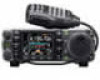
INSTRUCTION MANUAL HF/VHF/UHF ALL MODE TRANSCEIVER i7000
INSTRUCTION MANUAL HF/VHF/UHF ALL MODE TRANSCEIVER i7000
Instruction Manual
Page 163
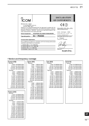
...MHz 50.000-52.000000 MHz 144.000-146.00000 MHz 430.000-440.00000 MHz 21 154 Kind of equipment: HF/VHF/UHF ALL MODE TRANSCEIVER Type-designation: i7000 Version (where applicable): This compliance is based on our sole responsibility that this equipment complies with the ... (2000-09) iv) EN 60950-1 (2001): A11: 2004 v) a Düsseldorf 21st Nov. 2005 H. ABOUT CE 21 DECLARATION OF CONFORMITY We Icom Inc. Japan 1-1-32, Kamiminami, Hirano-ku Osaka 547-0003, Japan Declare on conformity with the essential requirements of the Radio and Telecommunications Terminal Equipment Directive...
...MHz 50.000-52.000000 MHz 144.000-146.00000 MHz 430.000-440.00000 MHz 21 154 Kind of equipment: HF/VHF/UHF ALL MODE TRANSCEIVER Type-designation: i7000 Version (where applicable): This compliance is based on our sole responsibility that this equipment complies with the ... (2000-09) iv) EN 60950-1 (2001): A11: 2004 v) a Düsseldorf 21st Nov. 2005 H. ABOUT CE 21 DECLARATION OF CONFORMITY We Icom Inc. Japan 1-1-32, Kamiminami, Hirano-ku Osaka 547-0003, Japan Declare on conformity with the essential requirements of the Radio and Telecommunications Terminal Equipment Directive...

Service Manual
Page 1
SERVICE MANUAL HF/VHF/UHF ALL MODE TRANSCEIVER S-14214HZ-C1 Dec. 2005
SERVICE MANUAL HF/VHF/UHF ALL MODE TRANSCEIVER S-14214HZ-C1 Dec. 2005
Service Manual
Page 2
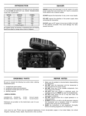
.... Component name and informations 3. An insulated turning tool MUST be used for the IC-7000 HF/VHF/UHF ALL MODE TRANSCEIVER at the time of the variable components. DO NOT expose the transceiver to include the following four points when ordering replacement parts: 1. 10-digit Icom parts number 2. This could cause a fire or electric hazard. DO NOT open...
.... Component name and informations 3. An insulated turning tool MUST be used for the IC-7000 HF/VHF/UHF ALL MODE TRANSCEIVER at the time of the variable components. DO NOT expose the transceiver to include the following four points when ordering replacement parts: 1. 10-digit Icom parts number 2. This could cause a fire or electric hazard. DO NOT open...

Service Manual
Page 11
...reference voltage. The AM switch (Q1602) is applied to adjust the TX output power for the AM mode (maximum; 40 W for HF/50 MHz bands, 20 W for VHF band, 14 W for UHF band). The ALC bias voltage from IC1601 is identical to that of the internal ALC. 3-2-11 APC CIRCUIT (MAIN UNIT) The... (PA unit; D961, D962) and then applied to the ALC amplifier (IC1601, pins 8, 9) as the "ALCL" voltage for the transceiver to the buffer amplifier (PA unit; J1). The amplified VHF RF signal from the [ACC] socket (pin 6) is converted to a positive voltage at the power amplifier (Q501) to the pre drive...
...reference voltage. The AM switch (Q1602) is applied to adjust the TX output power for the AM mode (maximum; 40 W for HF/50 MHz bands, 20 W for VHF band, 14 W for UHF band). The ALC bias voltage from IC1601 is identical to that of the internal ALC. 3-2-11 APC CIRCUIT (MAIN UNIT) The... (PA unit; D961, D962) and then applied to the ALC amplifier (IC1601, pins 8, 9) as the "ALCL" voltage for the transceiver to the buffer amplifier (PA unit; J1). The amplified VHF RF signal from the [ACC] socket (pin 6) is converted to a positive voltage at the power amplifier (Q501) to the pre drive...


