

Service Manual
Page 1
... Model N3 CHASSIS Picture tube Viewable image size Resolution Standard image area SPECIFICATIONS 0.25 - 0.27 mm aperture grille pitch 19 inches measured diagonally 90-degree deflection Approx. 365 × 273 mm (w/h) (14 3/8 × 10 3/4 inches) 18.0" viewing image Horizontal: Max. 1600 dots Vertical: Max. 1200 lines Approx. 330 × 264 mm (w/h) (13 × 10 1/2 inches) or Approx. 352 × 264 mm (w/h) (13 7/8 × 10 1/2 inches) Deflection frequency Horizontal...
... Model N3 CHASSIS Picture tube Viewable image size Resolution Standard image area SPECIFICATIONS 0.25 - 0.27 mm aperture grille pitch 19 inches measured diagonally 90-degree deflection Approx. 365 × 273 mm (w/h) (14 3/8 × 10 3/4 inches) 18.0" viewing image Horizontal: Max. 1600 dots Vertical: Max. 1200 lines Approx. 330 × 264 mm (w/h) (13 × 10 1/2 inches) or Approx. 352 × 264 mm (w/h) (13 7/8 × 10 1/2 inches) Deflection frequency Horizontal...
Service Manual
Page 2
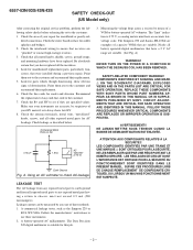
... TEST The AC leakage from any exposed metal part having a return to check AC leakage. Check the interboard wiring to use these instruments. 2. A. The Data Precision 245 digital multimeter is 0.75 V, so analog meters must not exceed 0.5 mA (500 microampers). AVERTISSEMENT!! Check that were installed during a previous repair. Check the line cords for parts which, though functioning, show obvious signs of a VOM...
... TEST The AC leakage from any exposed metal part having a return to check AC leakage. Check the interboard wiring to use these instruments. 2. A. The Data Precision 245 digital multimeter is 0.75 V, so analog meters must not exceed 0.5 mA (500 microampers). AVERTISSEMENT!! Check that were installed during a previous repair. Check the line cords for parts which, though functioning, show obvious signs of a VOM...

Service Manual
Page 3
... video graphics board that is input to "Setting the power saving delay time" on page 15. Power consumption mode 1 Normal operation 2 Standby (1st mode) Screen active blank 3 Suspend (2nd mode) blank 4 Active-off (3rd mode) 5 Power-off mode and the u indicator lights up orange. Horizontal sync signal present absent present absent - Reliability Check Mode : During Power Save, press "CONTRAST"- (?) key for longer than 2 second. 6557-03N/03S/43N/43S POWER SAVING FUNCTION This monitor meets the power-saving...
... video graphics board that is input to "Setting the power saving delay time" on page 15. Power consumption mode 1 Normal operation 2 Standby (1st mode) Screen active blank 3 Suspend (2nd mode) blank 4 Active-off (3rd mode) 5 Power-off mode and the u indicator lights up orange. Horizontal sync signal present absent present absent - Reliability Check Mode : During Power Save, press "CONTRAST"- (?) key for longer than 2 second. 6557-03N/03S/43N/43S POWER SAVING FUNCTION This monitor meets the power-saving...

Service Manual
Page 5
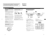
... 2-2 2-5. Picture Tube Removal 2-4 3. SAFETY RELATED ADJUSTMENT 3-1 4. Chassis 6-1 6-2. DISASSEMBLY 2-1. H Boards Removal 2-3 2-7. DIAGRAMS 5-1. Picture Tube 6-2 6-3. GENERAL 1-1 2. Circuit Boards Location 5-4 5-3. A Board Removal 2-1 2-3. Service Position 2-3 2-6. EXPLODED VIEWS 6-1. ADJUSTMENTS 4-1 5. Block Diagrams (with Frame Schematic Diagram 5-1 5-2. Schematic Diagrams and Printed Wiring Boards 5-4 (1) Schematic Diagram of D Board 5-5 (2) Schematic Diagram of A Board 5-13 (3) Schematic Diagram of H Board 5-16 5-4. ELECTRICAL PARTS LIST...
... 2-2 2-5. Picture Tube Removal 2-4 3. SAFETY RELATED ADJUSTMENT 3-1 4. Chassis 6-1 6-2. DISASSEMBLY 2-1. H Boards Removal 2-3 2-7. DIAGRAMS 5-1. Picture Tube 6-2 6-3. GENERAL 1-1 2. Circuit Boards Location 5-4 5-3. A Board Removal 2-1 2-3. Service Position 2-3 2-6. EXPLODED VIEWS 6-1. ADJUSTMENTS 4-1 5. Block Diagrams (with Frame Schematic Diagram 5-1 5-2. Schematic Diagrams and Printed Wiring Boards 5-4 (1) Schematic Diagram of D Board 5-5 (2) Schematic Diagram of A Board 5-13 (3) Schematic Diagram of H Board 5-16 5-4. ELECTRICAL PARTS LIST...
Service Manual
Page 6
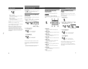
... on the CRT display surface to the factory settings. 2 (auto sizing and centering) button (page 5) Automatically adjusts the size and centering of the Tilt-Swivel With the tilt-swivel, this monitor. Use of the images. 3 ¨ (brightness) (./>) buttons (pages 5 - 14) Adjust the picture brightness. EN 8 Video input 1 connector (HD15) F Inputs RGB video signals (0.700 Vp-p, positive) and SYNC signals. The indicator lights up in green when the monitor is in power saving mode. 7 AC IN connector Provides AC power to the desired angle within 180° horizontally and...
... on the CRT display surface to the factory settings. 2 (auto sizing and centering) button (page 5) Automatically adjusts the size and centering of the Tilt-Swivel With the tilt-swivel, this monitor. Use of the images. 3 ¨ (brightness) (./>) buttons (pages 5 - 14) Adjust the picture brightness. EN 8 Video input 1 connector (HD15) F Inputs RGB video signals (0.700 Vp-p, positive) and SYNC signals. The indicator lights up in green when the monitor is in power saving mode. 7 AC IN connector Provides AC power to the desired angle within 180° horizontally and...
Service Manual
Page 7
... sync input and as follows. 1 Turn on page 14. 1-2 Getting Started 9 Video input 2 connector (13W3 cable) Inputs RGB video signal (0.700 Vp-p, positive). 12 345 6 7 8 9 10 Setup This monitor works with a computer running at horizontal frequencies between 30 and 94 kHz. A1 A2 A3 Pin No. In such case, try decreasing the picture contrast, or use with platforms running graphic user interface software that provides a full-screen picture. Step2: Connectthepowercord With the monitor switched off , connect the video signal cable to a power...
... sync input and as follows. 1 Turn on page 14. 1-2 Getting Started 9 Video input 2 connector (13W3 cable) Inputs RGB video signal (0.700 Vp-p, positive). 12 345 6 7 8 9 10 Setup This monitor works with a computer running at horizontal frequencies between 30 and 94 kHz. A1 A2 A3 Pin No. In such case, try decreasing the picture contrast, or use with platforms running graphic user interface software that provides a full-screen picture. Step2: Connectthepowercord With the monitor switched off , connect the video signal cable to a power...
Service Manual
Page 8
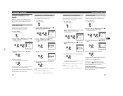
... frequencies for the current input signal. 1 Press the button. Adjusting the Picture Brightness and Contrast Once the setting is in memory for the received input signal appear in the BRIGHTNESS/CONTRAST OSD. 6 GCeuttsitnogmSiztianrgteYdour Monitor Introducing the On-screen Display System Most adjustments are both reset to view, or that computer is adjusted, it will be stored in power saving mode, the monitor may automatically select the other OSDs described below. BRIGHTNESS/CONTRAST 26 26 80.0kHz/ 75Hz Horizontal Vertical Frequency* Frequency* 2 For brightness adjustment...
... frequencies for the current input signal. 1 Press the button. Adjusting the Picture Brightness and Contrast Once the setting is in memory for the received input signal appear in the BRIGHTNESS/CONTRAST OSD. 6 GCeuttsitnogmSiztianrgteYdour Monitor Introducing the On-screen Display System Most adjustments are both reset to view, or that computer is adjusted, it will be stored in power saving mode, the monitor may automatically select the other OSDs described below. BRIGHTNESS/CONTRAST 26 26 80.0kHz/ 75Hz Horizontal Vertical Frequency* Frequency* 2 For brightness adjustment...

Service Manual
Page 9
... . Note The picture zoom adjustment will be stored in memory for the current input signal. 1 Press the button. Once the setting is on. to decrease picture height The OSD automatically disappears after about 30 seconds. ES C / . . . Customizing Your Monitor Using the SIZE On-screen Display The SIZE settings allow you to adjust the shape and orientation of the picture. The horizontal and vertical sizes are both reset to the factory settings. For ROTATION Press...
... . Note The picture zoom adjustment will be stored in memory for the current input signal. 1 Press the button. Once the setting is on. to decrease picture height The OSD automatically disappears after about 30 seconds. ES C / . . . Customizing Your Monitor Using the SIZE On-screen Display The SIZE settings allow you to adjust the shape and orientation of the picture. The horizontal and vertical sizes are both reset to the factory settings. For ROTATION Press...

Service Manual
Page 10
... R (red), G (green), or B (blue) BIAS to turn the moire cancellation function "ON" or "OFF." to select the color temperature. Select H CONVERGENCE V CONVERGENCE TOP V CONVER TOP BOT V CONVER BOTTOM To adjust the horizontal convergence adjust the vertical convergence adjust the screen's upper vertical convergence adjust the screen's lower vertical convergence GCeuttsitnogmSiztianrgteYdour Monitor Select CANCEL MOIRE * ADJ MOIRE ADJUST To turn CANCEL MOIRE "ON" OFF ON ? . . . F To reset, press the ? (reset) button while...
... R (red), G (green), or B (blue) BIAS to turn the moire cancellation function "ON" or "OFF." to select the color temperature. Select H CONVERGENCE V CONVERGENCE TOP V CONVER TOP BOT V CONVER BOTTOM To adjust the horizontal convergence adjust the vertical convergence adjust the screen's upper vertical convergence adjust the screen's lower vertical convergence GCeuttsitnogmSiztianrgteYdour Monitor Select CANCEL MOIRE * ADJ MOIRE ADJUST To turn CANCEL MOIRE "ON" OFF ON ? . . . F To reset, press the ? (reset) button while...
Service Manual
Page 11
...panel except the u (power) switch and button. 1 Press the button. The MENU OSD appears. 2 Press the ¨./> and >?// buttons to select "LOCK." Select " (OSD H POSITION)" to select " LOCK)." (CONTROL OPTION 1 ZZ... GCeuttsitnogmSiztianrgteYdour Monitor Locking the controls The control lock function disables all of the buttons on . The OPTION OSD appears. 1-6 Customizing Your Monitor Using the OPTION On-screen Display The OPTION OSD allows you to lock the controls. You can set to manually degauss the screen and adjust settings such as the OSD position and power saving...
...panel except the u (power) switch and button. 1 Press the button. The MENU OSD appears. 2 Press the ¨./> and >?// buttons to select "LOCK." Select " (OSD H POSITION)" to select " LOCK)." (CONTROL OPTION 1 ZZ... GCeuttsitnogmSiztianrgteYdour Monitor Locking the controls The control lock function disables all of the buttons on . The OPTION OSD appears. 1-6 Customizing Your Monitor Using the OPTION On-screen Display The OPTION OSD allows you to lock the controls. You can set to manually degauss the screen and adjust settings such as the OSD position and power saving...

Service Manual
Page 12
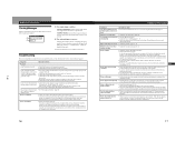
... board that adjustment data not affected by VESA and Energy Star, as well as shown below . After the delay time has passed, the power saving function automatically puts the monitor into the active-off - Power consumption mode Screen Horizontal sync signal Vertical sync signal Power consumption Recovery time u indicator 1 Normal operation active present present ≤ 140 W - absent - < 5 W 0 W Approx. 10 sec. - To reset to English, press the ? (reset) button while the OSD...
... board that adjustment data not affected by VESA and Energy Star, as well as shown below . After the delay time has passed, the power saving function automatically puts the monitor into the active-off - Power consumption mode Screen Horizontal sync signal Vertical sync signal Power consumption Recovery time u indicator 1 Normal operation active present present ≤ 140 W - absent - < 5 W 0 W Approx. 10 sec. - To reset to English, press the ? (reset) button while the OSD...
Service Manual
Page 13
... GettAindgdSittiaorntaeldInformation Symptom Check these items You cannot adjust the monitor • If the control lock function is set it is correct. Excessive cable length or a weak connection can produce this manual and confirm that the input signal is not supported by referring to adjust the video frequency range. • If you isolate the cause of the monitor, color may be modified depending on the screen (Horizontal: 30 - 94 kHz, Vertical: 50...
... GettAindgdSittiaorntaeldInformation Symptom Check these items You cannot adjust the monitor • If the control lock function is set it is correct. Excessive cable length or a weak connection can produce this manual and confirm that the input signal is not supported by referring to adjust the video frequency range. • If you isolate the cause of the monitor, color may be modified depending on the screen (Horizontal: 30 - 94 kHz, Vertical: 50...

Service Manual
Page 14
... specifications are subject to note the model name and serial number of your service representative of your monitor or computer(s), the screen will go blank and the u indicator will either light up green, the monitor is a problem with a self-diagnosis function. Also note the make and model of the monitor's condition. If the color bars do not appear, there is green 1 Remove any plugs from the video input 1 and 2 connectors, or turn...
... specifications are subject to note the model name and serial number of your service representative of your monitor or computer(s), the screen will go blank and the u indicator will either light up green, the monitor is a problem with a self-diagnosis function. Also note the make and model of the monitor's condition. If the color bars do not appear, there is green 1 Remove any plugs from the video input 1 and 2 connectors, or turn...

Service Manual
Page 18
... c. 2-4 The shatter-hook terminal will stick out or hurt the rubber. firmly in the rubber. 3 Don't turn the foot of anode-caps! Anode Button 3 When one side of the rubber cap is built in the direction indicated by the arrow a. PICTURE TUBE REMOVAL 2 Three connectors CN2 (DY) GND (DY) CN4 (DY) 1 Anode cap 4 Two screws (+ BVTT 4 x 8) 3 A board 6 Neck...
... c. 2-4 The shatter-hook terminal will stick out or hurt the rubber. firmly in the rubber. 3 Don't turn the foot of anode-caps! Anode Button 3 When one side of the rubber cap is built in the direction indicated by the arrow a. PICTURE TUBE REMOVAL 2 Three connectors CN2 (DY) GND (DY) CN4 (DY) 1 Anode cap 4 Two screws (+ BVTT 4 x 8) 3 A board 6 Neck...

Service Manual
Page 19
... ADJUSTMENT 6557-03N/03S/43N/43S When replacing or repairing the shown below table, the following operational checks must be performed as a safety precaution against X-rays emissions from maximum to minimum, and confirm that the Beam Current Protector Circuite works (TV Raster disappears). HV ADJ Part Replaced ([) RV901 Part Replaced (]) HV Regulator Circuit D board IC901, R903, R922, T901, RV901 • Mounted D board...
... ADJUSTMENT 6557-03N/03S/43N/43S When replacing or repairing the shown below table, the following operational checks must be performed as a safety precaution against X-rays emissions from maximum to minimum, and confirm that the Beam Current Protector Circuite works (TV Raster disappears). HV ADJ Part Replaced ([) RV901 Part Replaced (]) HV Regulator Circuit D board IC901, R903, R922, T901, RV901 • Mounted D board...

Service Manual
Page 20
... wedges. Tighten DY screw. Remove the sensor and wobbling coil. 12. Check that the DY will not loosen.) Fixing DY with respect to the green. Enter the full white signal. (or the full black dots signal). 2. Reverse the DY, and adjust coarsely the purity magnet so that a green raster positions in specification, adjust by switching DY neck up-down, and adjust V. Put the set at each top...
... wedges. Tighten DY screw. Remove the sensor and wobbling coil. 12. Check that the DY will not loosen.) Fixing DY with respect to the green. Enter the full white signal. (or the full black dots signal). 2. Reverse the DY, and adjust coarsely the purity magnet so that a green raster positions in specification, adjust by switching DY neck up-down, and adjust V. Put the set at each top...
Service Manual
Page 21
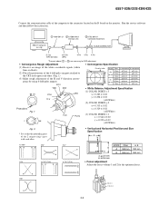
... DAS adjustment. • Convergence Rough Adjustment (1) Receive an image of the white crosshatch signals (white lines on black). (2) Place the protrusions of the 6-fold poles magnet attached to the CRT neck upon each other. (Fig. 1) (3) Make rough adjustment of the computer to the connector located on the D board on the monitor. Hemisphere S. gence by using 4-fold poles magnet. Run the service software and then follow the instruction.
... DAS adjustment. • Convergence Rough Adjustment (1) Receive an image of the white crosshatch signals (white lines on black). (2) Place the protrusions of the 6-fold poles magnet attached to the CRT neck upon each other. (Fig. 1) (3) Make rough adjustment of the computer to the connector located on the D board on the monitor. Hemisphere S. gence by using 4-fold poles magnet. Run the service software and then follow the instruction.
Service Manual
Page 23
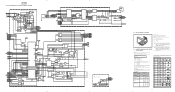
... PICTURE TUBE FV1 FV2 H(USER CONTROL) D806 POWER LED DRIVE Q803 LED DRIVE Q802 CN801 8 ENV_TEMP 5 KEY_DET 4 LED3 3 LED2 E 2 LED1 1 LED0 S807 S806 RESET ASC S804 BRT- Replace only with a color-bar signal input. • Voltage variations may be noted due to normal production tolerances. * • : Can not be measured. • Circled numbers are waveform references. • s : B + bus. • S : B - SCHEMATIC DIAGRAMS AND PRINTED WIRING BOARDS...
... PICTURE TUBE FV1 FV2 H(USER CONTROL) D806 POWER LED DRIVE Q803 LED DRIVE Q802 CN801 8 ENV_TEMP 5 KEY_DET 4 LED3 3 LED2 E 2 LED1 1 LED0 S807 S806 RESET ASC S804 BRT- Replace only with a color-bar signal input. • Voltage variations may be noted due to normal production tolerances. * • : Can not be measured. • Circled numbers are waveform references. • s : B + bus. • S : B - SCHEMATIC DIAGRAMS AND PRINTED WIRING BOARDS...

Service Manual
Page 24
...BOARD 6P DGC AC INLET CN406 :S-MICRO Schematic diagrams D boards l 5-6 5-7 • D BOARD WAVEFORMS 1 5.0 Vp-p (4MHz) 2 4.5 Vp-p (H) 3 2.0 Vp-p (H) 4 600 Vp-p (H) 5 45.0 Vp-p (H) 6 45.0 Vp-p (V) 7 1.0 Vp-p (V) • D BOARD IC1502 LA6510 +VIN1 VCC +VIN2 4 10 6 VOUT1 2 VSENCE1 1 CURRENT CONTROLLED CIRCUIT CURRENT CONTROLLED CIRCUIT 8 VOUT2 9 VSENCE2 357 -VIN1 VEE -VIN2 • D BOARD...D609 D1NL20U-TR POWER SUPPLY,U-COM, D DEFLECTION C640 0.01 :PT 1 GND... WHT TXD 4 RXD 3 +5V 2 GND 1 FOR BUS SYNC ON G 1 GND 2 AUTO S/C 3 S/C ENABLE 4 INPUT_SEL 5 CLAMP 6 H BLK ...
...BOARD 6P DGC AC INLET CN406 :S-MICRO Schematic diagrams D boards l 5-6 5-7 • D BOARD WAVEFORMS 1 5.0 Vp-p (4MHz) 2 4.5 Vp-p (H) 3 2.0 Vp-p (H) 4 600 Vp-p (H) 5 45.0 Vp-p (H) 6 45.0 Vp-p (V) 7 1.0 Vp-p (V) • D BOARD IC1502 LA6510 +VIN1 VCC +VIN2 4 10 6 VOUT1 2 VSENCE1 1 CURRENT CONTROLLED CIRCUIT CURRENT CONTROLLED CIRCUIT 8 VOUT2 9 VSENCE2 357 -VIN1 VEE -VIN2 • D BOARD...D609 D1NL20U-TR POWER SUPPLY,U-COM, D DEFLECTION C640 0.01 :PT 1 GND... WHT TXD 4 RXD 3 +5V 2 GND 1 FOR BUS SYNC ON G 1 GND 2 AUTO S/C 3 S/C ENABLE 4 INPUT_SEL 5 CLAMP 6 H BLK ...

Service Manual
Page 33
...PART NO. PART NO. DESCRIPTION REMARK 107 4-063-796-01 INFORMATION DISK (IBM) 108 ¡ 1-783-507-11 CORD SET, POWER (10A/125V) [43N NH model] 108 ¡ 1-783-507-21 CORD SET, POWER (10A/125V) [03N NH model] 108 ¡ 1-783-533-11 CORD SET, POWER (7A/125V) [03N/43N Japan model] 109 3-862-445-01 MANUAL, INSTRUCTION [03N/43N Japan model] 109 3-862-445-11 MANUAL, INSTRUCTION...01 PAD, TILT FIXED 104 4-062-475-01 CUSHION (LOWER) (ASSY) 105 4-063-550-01 INDIVIDUAL CARTON 106 1-783-247-11 CABLE ASSY (15P D SUB X2 CONNECTOR) [03N/03S] 106 1-783-250-11 CABLE ASSY (15P D SUB X2 CONNECTOR) [43N/...
...PART NO. PART NO. DESCRIPTION REMARK 107 4-063-796-01 INFORMATION DISK (IBM) 108 ¡ 1-783-507-11 CORD SET, POWER (10A/125V) [43N NH model] 108 ¡ 1-783-507-21 CORD SET, POWER (10A/125V) [03N NH model] 108 ¡ 1-783-533-11 CORD SET, POWER (7A/125V) [03N/43N Japan model] 109 3-862-445-01 MANUAL, INSTRUCTION [03N/43N Japan model] 109 3-862-445-11 MANUAL, INSTRUCTION...01 PAD, TILT FIXED 104 4-062-475-01 CUSHION (LOWER) (ASSY) 105 4-063-550-01 INDIVIDUAL CARTON 106 1-783-247-11 CABLE ASSY (15P D SUB X2 CONNECTOR) [03N/03S] 106 1-783-250-11 CABLE ASSY (15P D SUB X2 CONNECTOR) [43N/...

