
Parts Manual
Page 15
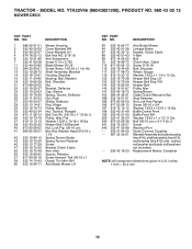
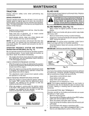
... 3/4 Washer 13/32 x 13/16 x 12 Ga. pulley/ nut/washer and blade bolt/washers not included) Replacement Mower, Complete NOTE: All component dimensions given in U.S. YTA22V46 (96043021200), PRODUCT NO. 960 43 02 12 MOWER DECK KEY PART NO. Cable Screw 5/16-18 Bolt, Shoulder Wheel, Gauge Washer 13/32 x 1-1/4 x 12 Ga...- - 532 43 18-23 Arm Brake Mower Linkage Brake Handle, Clutch Cable V-Belt Bolt Clutch Asm. RH Keeper Belt Pulley Idler Spring Return Cable Clutch Manual w/Spr. DESCRIPTION 1 586 29 31-01 Mower Housing 2 532 40 55-06 Cover Mandrel RH 3 532 40 55-07 Cover Mandrel LH 4 874 76...
... 3/4 Washer 13/32 x 13/16 x 12 Ga. pulley/ nut/washer and blade bolt/washers not included) Replacement Mower, Complete NOTE: All component dimensions given in U.S. YTA22V46 (96043021200), PRODUCT NO. 960 43 02 12 MOWER DECK KEY PART NO. Cable Screw 5/16-18 Bolt, Shoulder Wheel, Gauge Washer 13/32 x 1-1/4 x 12 Ga...- - 532 43 18-23 Arm Brake Mower Linkage Brake Handle, Clutch Cable V-Belt Bolt Clutch Asm. RH Keeper Belt Pulley Idler Spring Return Cable Clutch Manual w/Spr. DESCRIPTION 1 586 29 31-01 Mower Housing 2 532 40 55-06 Cover Mandrel RH 3 532 40 55-07 Cover Mandrel LH 4 874 76...
Parts Manual
Page 18
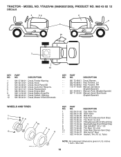
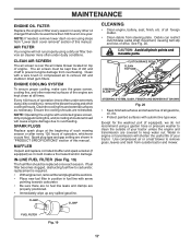
... 96-82 115 77 70-26 501 40 84-01 587 71 00-26 Decal, Bypass Pad, Footrest, LH Pad, Footrest, RH Manual, Operators (English/Spanish) Manual, Parts (English/Spanish) Manual, Quick Start Guide (English/Spanish) WHEELS AND TIRES 1 2 11 3 4 7 10 6 wheel_art_1-tex 5 9 8 KEY NO. 1 2 3 4 5 6 ...) Bearing Flange (Front Wheel Only) Cap Axle Blk 1 50 x 1 00 Tire Rear 20 x 8-8 Tube Rear (Service Item Only) Rim Asm 8" Rear Sealant, Tire (10 oz. YTA22V46 (96043021200), PRODUCT NO. 960 43 02 12 DECALS 2 56 2 9 3 1 10 7 12 KEY NO. 1 2 3 5 6 7 9 10 12 PART NO. Warning Decal, Mower V-...
... 96-82 115 77 70-26 501 40 84-01 587 71 00-26 Decal, Bypass Pad, Footrest, LH Pad, Footrest, RH Manual, Operators (English/Spanish) Manual, Parts (English/Spanish) Manual, Quick Start Guide (English/Spanish) WHEELS AND TIRES 1 2 11 3 4 7 10 6 wheel_art_1-tex 5 9 8 KEY NO. 1 2 3 4 5 6 ...) Bearing Flange (Front Wheel Only) Cap Axle Blk 1 50 x 1 00 Tire Rear 20 x 8-8 Tube Rear (Service Item Only) Rim Asm 8" Rear Sealant, Tire (10 oz. YTA22V46 (96043021200), PRODUCT NO. 960 43 02 12 DECALS 2 56 2 9 3 1 10 7 12 KEY NO. 1 2 3 5 6 7 9 10 12 PART NO. Warning Decal, Mower V-...

Operation Manual
Page 2
...past may ricochet back toward anyone enters the area. • Never carry passengers. • Do not mow in the Operation section of this manual). • Disengage blades when not mowing. Allow machine to cause cancer and birth defects or other reproductive harm. WARNING Battery posts, terminals ...and related accessories contain lead and lead compounds, chemicals known to the State of grass, leaves or other safety devices in the manual before dismounting. Too heavy of a load, while on a slope, is not alert to operate the machine. • Clear the area of...
...past may ricochet back toward anyone enters the area. • Never carry passengers. • Do not mow in the Operation section of this manual). • Disengage blades when not mowing. Allow machine to cause cancer and birth defects or other reproductive harm. WARNING Battery posts, terminals ...and related accessories contain lead and lead compounds, chemicals known to the State of grass, leaves or other safety devices in the manual before dismounting. Too heavy of a load, while on a slope, is not alert to operate the machine. • Clear the area of...

Operation Manual
Page 4
... or grass-covered land unless the engine's exhaust system is available through your tractor properly. In the state of this manual. • Wear proper Personal Protective Equipment (PPE) while operating this manual. Other states may have competent, well-trained technicians and the proper tools to assemble and maintain your nearest authorized service...
... or grass-covered land unless the engine's exhaust system is available through your tractor properly. In the state of this manual. • Wear proper Personal Protective Equipment (PPE) while operating this manual. Other states may have competent, well-trained technicians and the proper tools to assemble and maintain your nearest authorized service...

Operation Manual
Page 5
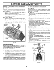
...for minimum of one hour at 6-10 amps. (See "BATTERY" in the Maintenance section of those parts left hand is mentioned in this manual, it means when you to press clutch/brake pedal all accessible loose parts and parts cartons from accidental grounding. Tighten securely. NOTE: For battery...must be under the seat or the hood. POSITIVE (RED) CABLE 02605 NEGATIVE (BLACK) CABLE Fig. 1 ADJUST SEAT (See Fig. 2) • Sit in this manual. A Fig. 2 5 TO REMOVE TRACTOR FROM CARTON • Lift seat pan or hood to raised position. • Remove two terminal caps and discard. •...
...for minimum of one hour at 6-10 amps. (See "BATTERY" in the Maintenance section of those parts left hand is mentioned in this manual, it means when you to press clutch/brake pedal all accessible loose parts and parts cartons from accidental grounding. Tighten securely. NOTE: For battery...must be under the seat or the hood. POSITIVE (RED) CABLE 02605 NEGATIVE (BLACK) CABLE Fig. 1 ADJUST SEAT (See Fig. 2) • Sit in this manual. A Fig. 2 5 TO REMOVE TRACTOR FROM CARTON • Lift seat pan or hood to raised position. • Remove two terminal caps and discard. •...
Operation Manual
Page 6
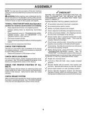
...depressing clutch/brake pedal. • Place freewheel control in "TRANSMISSION DISENGAGED" position. (See "TO TRANSPORT" in the Operation section of this manual.) • Roll tractor forward off the skid. PLEASE REVIEW THE FOLLOWING CHECKLIST: ✓ All assembly instructions have been completed. ✓ .... WARNING: Before starting, read, understand and follow . See "TO CHECK BRAKE" in the Service and Adjustments section of this manual. CHECK TIRE PRESSURE The tires on tires. Continue using the instructions that the belts are shown for best cutting performance. •...
...depressing clutch/brake pedal. • Place freewheel control in "TRANSMISSION DISENGAGED" position. (See "TO TRANSPORT" in the Operation section of this manual.) • Roll tractor forward off the skid. PLEASE REVIEW THE FOLLOWING CHECKLIST: ✓ All assembly instructions have been completed. ✓ .... WARNING: Before starting, read, understand and follow . See "TO CHECK BRAKE" in the Service and Adjustments section of this manual. CHECK TIRE PRESSURE The tires on tires. Continue using the instructions that the belts are shown for best cutting performance. •...
Operation Manual
Page 8
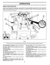
Save this manual for starting and controlling engine speed. (L) REVERSE DRIVE PEDAL - Used for future reference. Disengages transmission for forward movement of tractor. (D) THROTTLE/CHOKE CONTROL - ...SYSTEM (ROS) "ON" POSITION - Indicates when service is required for reverse movement of tractor. (E) ATTACHMENT CLUTCH LEVER - OPERATION KNOW YOUR TRACTOR READ THIS OPERATOR'S MANUAL AND SAFETY RULES BEFORE OPERATING YOUR TRACTOR Compare the illustrations with your tractor to the applicable safety standards of the American National Standards Institute. (A) ATTACHMENT...
Save this manual for starting and controlling engine speed. (L) REVERSE DRIVE PEDAL - Used for future reference. Disengages transmission for forward movement of tractor. (D) THROTTLE/CHOKE CONTROL - ...SYSTEM (ROS) "ON" POSITION - Indicates when service is required for reverse movement of tractor. (E) ATTACHMENT CLUTCH LEVER - OPERATION KNOW YOUR TRACTOR READ THIS OPERATOR'S MANUAL AND SAFETY RULES BEFORE OPERATING YOUR TRACTOR Compare the illustrations with your tractor to the applicable safety standards of the American National Standards Institute. (A) ATTACHMENT...
Operation Manual
Page 10
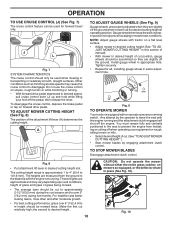
... lever (A) determines the cutting height. The cutting height range is at slow speeds may vary depending upon soil conditions, height of grass and types of manual). • With mower in most terrain conditions. To disengage the cruise control, depress the brake pedal or tap on a flat level surface. • Adjust mower...
... lever (A) determines the cutting height. The cutting height range is at slow speeds may vary depending upon soil conditions, height of grass and types of manual). • With mower in most terrain conditions. To disengage the cruise control, depress the brake pedal or tap on a flat level surface. • Adjust mower...
Operation Manual
Page 11
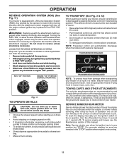
...will stay on hills. • If stopping is dangerous. SERVICE MINDER/HOUR METER Service minder shows the total number of this manual. TRANSMISSION ENGAGED TRANSMISSION DISENGAGED NOTE: To protect hood from damage when transporting your tractor. Note: Service minder runs when the ...; To restart movement, slowly release parking brake and brake pedal. • Slowly depress appropriate drive pedal to tractor. To reset the display manually turn the ignition key clockwise to tractor (rope, cord, etc.). Use common sense when towing. OPERATION REVERSE OPERATION SYSTEM (ROS) (See...
...will stay on hills. • If stopping is dangerous. SERVICE MINDER/HOUR METER Service minder shows the total number of this manual. TRANSMISSION ENGAGED TRANSMISSION DISENGAGED NOTE: To protect hood from damage when transporting your tractor. Note: Service minder runs when the ...; To restart movement, slowly release parking brake and brake pedal. • Slowly depress appropriate drive pedal to tractor. To reset the display manually turn the ignition key clockwise to tractor (rope, cord, etc.). Use common sense when towing. OPERATION REVERSE OPERATION SYSTEM (ROS) (See...
Operation Manual
Page 12
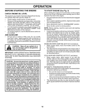
... WARM UP • Before driving the unit in cold weather, the transmission should change engine oil, see the Maintenance section in this manual.) • To change oil for easier starting the engine for transmission to the choke position and retry. ADD GASOLINE • Fill fuel... quantities that can also be warmed up period. • The attachments can be used within 30 days to separation and formation of this manual. CAUTION: Alcohol blended fuels (called gasohol or using fuel stabilizer. Do not overfill. • For cold weather operation you should be ...
... WARM UP • Before driving the unit in cold weather, the transmission should change engine oil, see the Maintenance section in this manual.) • To change oil for easier starting the engine for transmission to the choke position and retry. ADD GASOLINE • Fill fuel... quantities that can also be warmed up period. • The attachments can be used within 30 days to separation and formation of this manual. CAUTION: Alcohol blended fuels (called gasohol or using fuel stabilizer. Do not overfill. • For cold weather operation you should be ...

Operation Manual
Page 13
... reduce load and possible fire hazard from shrubs, fences, driveways, etc. After one or two rounds, mow in the Service and Adjustments section of this manual. • The left hand turns until finished (See Fig. 13). Fig. 13 • If grass is extremely tall, it should be mowed twice to the...
... reduce load and possible fire hazard from shrubs, fences, driveways, etc. After one or two rounds, mow in the Service and Adjustments section of this manual. • The left hand turns until finished (See Fig. 13). Fig. 13 • If grass is extremely tall, it should be mowed twice to the...
Operation Manual
Page 14
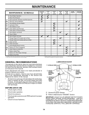
... LUBRICATED, USE ONLY A DRY, POWDERED GRAPHITE TYPE LUBRICANT SPARINGLY. 14 Replace blades more often when mowing in Maintenance Section. GENERAL RECOMMENDATIONS The warranty on this manual. • At least once a year you should make any of this tractor does not cover items that have been subjected to Maintenance "ENGINE" Section IMPORTANT.... 1, 2 2 2 5 - To receive full value from the warranty, operator must maintain tractor as instructed in the Service and Adjustments section of the adjustments described in this manual.
... LUBRICATED, USE ONLY A DRY, POWDERED GRAPHITE TYPE LUBRICANT SPARINGLY. 14 Replace blades more often when mowing in Maintenance Section. GENERAL RECOMMENDATIONS The warranty on this manual. • At least once a year you should make any of this tractor does not cover items that have been subjected to Maintenance "ENGINE" Section IMPORTANT.... 1, 2 2 2 5 - To receive full value from the warranty, operator must maintain tractor as instructed in the Service and Adjustments section of the adjustments described in this manual.
Operation Manual
Page 15
...with grease or petroleum jelly. Fig. 14 • 15 Reinstall battery. (See "REPLACING BATTERY" in the Service and Adjustments section of this manual.) TIRES • Maintain proper air pressure in the seat. Tire sealant also prevents tire dry rot and corrosion. BLADE REMOVAL (See Fig. ... or damaged blades. Adding or checking level of electrolyte is running with the ignition switch in the Service and Adjustments section of this manual.) OPERATOR PRESENCE SYSTEM AND REVERSE OPERATION SYSTEM (ROS) (See Fig. 14) CAUTION: Use only a replacement blade approved by the operator...
...with grease or petroleum jelly. Fig. 14 • 15 Reinstall battery. (See "REPLACING BATTERY" in the Service and Adjustments section of this manual.) TIRES • Maintain proper air pressure in the seat. Tire sealant also prevents tire dry rot and corrosion. BLADE REMOVAL (See Fig. ... or damaged blades. Adding or checking level of electrolyte is running with the ignition switch in the Service and Adjustments section of this manual.) OPERATOR PRESENCE SYSTEM AND REVERSE OPERATION SYSTEM (ROS) (See Fig. 14) CAUTION: Use only a replacement blade approved by the operator...

Operation Manual
Page 16
... OIL (See Fig. 16 - 18) Determine temperature range expected before starting in cold weather, they begin to avoid possible engine damage from end of this manual. • Use gauge on oil. LOWER DASH COVER 5W-30 SAE 30 F -20 0 30 32 40 60 80 100 C -30 -20 -10 0 10 20 30...
... OIL (See Fig. 16 - 18) Determine temperature range expected before starting in cold weather, they begin to avoid possible engine damage from end of this manual. • Use gauge on oil. LOWER DASH COVER 5W-30 SAE 30 F -20 0 30 32 40 60 80 100 C -30 -20 -10 0 10 20 30...
Operation Manual
Page 17
...intake blower located on top of engine. CLEAN AIR SCREEN The air screen is used more than 100 hours in "PRODUCT SPECIFICATIONS" section of this manual. Clean with a wire brush or compressed air to carburetor, replacement is required. • With engine cool, remove filter and plug fuel line sections... a fire hazard and/or damage. If fuel filter becomes clogged, obstructing fuel flow to remove dirt and stubborn dried gum fibers. of this manual. CLUTCH/BRAKE PEDAL CLEAN TOP SIDE STEERING PLATE STEERING SYSTEM, DASH, FENDER AND MOWER NOT SHOWN Fig. 20 • Keep finished surfaces and...
...intake blower located on top of engine. CLEAN AIR SCREEN The air screen is used more than 100 hours in "PRODUCT SPECIFICATIONS" section of this manual. Clean with a wire brush or compressed air to carburetor, replacement is required. • With engine cool, remove filter and plug fuel line sections... a fire hazard and/or damage. If fuel filter becomes clogged, obstructing fuel flow to remove dirt and stubborn dried gum fibers. of this manual. CLUTCH/BRAKE PEDAL CLEAN TOP SIDE STEERING PLATE STEERING SYSTEM, DASH, FENDER AND MOWER NOT SHOWN Fig. 20 • Keep finished surfaces and...

Operation Manual
Page 18
.... 8. Turn the ignition key to the STOP position to the "ENGAGED" position. Place the attachment clutch control in the operator's position with your tractor's Operator's Manual) onto the end of its deck wash system. Remain in the "ENGAGED" position to remove excess water and to the "DISENGAGED" position. Move the tractor...
.... 8. Turn the ignition key to the STOP position to the "ENGAGED" position. Place the attachment clutch control in the operator's position with your tractor's Operator's Manual) onto the end of its deck wash system. Remain in the "ENGAGED" position to remove excess water and to the "DISENGAGED" position. Move the tractor...

Operation Manual
Page 20
... of trac- Lift rear corner of tractor. Position hole in link assembly over pin (D) on engine pulley (M). tor. F J H Fig. 25 • Hook end of this manual. Fig. 26 IMPORTANT: CHECK BELT FOR PROPER ROUTING IN ALL MOWER PULLEY GROOVES. • Raise attachment lift lever to highest position. • If necessary, adjust...
... of trac- Lift rear corner of tractor. Position hole in link assembly over pin (D) on engine pulley (M). tor. F J H Fig. 25 • Hook end of this manual. Fig. 26 IMPORTANT: CHECK BELT FOR PROPER ROUTING IN ALL MOWER PULLEY GROOVES. • Raise attachment lift lever to highest position. • If necessary, adjust...
Operation Manual
Page 22
... section in the disengaged position. Remove belt from centerspan idler (C). 4. Slide belt toward front of left footrest. Be sure belt is held in this manual.) E F A B D G C Fig. 33 22 BELT INSTALLATION • Work belt around transaxle input pulley (D). Contact a qualified service center..... Install belt through stationary idler (A) and clutching idler (B). 6. You may be replaced without tools. Pull belt toward rear of manual). Install mower. (See "TO INSTALL MOWER" section in all pulley grooves and inside all belt guides and keepers. 2. If ...
... section in the disengaged position. Remove belt from centerspan idler (C). 4. Slide belt toward front of left footrest. Be sure belt is held in this manual.) E F A B D G C Fig. 33 22 BELT INSTALLATION • Work belt around transaxle input pulley (D). Contact a qualified service center..... Install belt through stationary idler (A) and clutching idler (B). 6. You may be replaced without tools. Pull belt toward rear of manual). Install mower. (See "TO INSTALL MOWER" section in all pulley grooves and inside all belt guides and keepers. 2. If ...

Operation Manual
Page 23
... and washers to affect the factory set at the same time. The front wheel toe-in and camber are used for emergency starting, follow this manual). If damage has occurred to allow wheel removal (rear wheel contains a square key - Positive terminal must be recharged. (See "BATTERY" in and camber is normal...
... and washers to affect the factory set at the same time. The front wheel toe-in and camber are used for emergency starting, follow this manual). If damage has occurred to allow wheel removal (rear wheel contains a square key - Positive terminal must be recharged. (See "BATTERY" in and camber is normal...

Operation Manual
Page 24
...run poorly, stop running, or prevent it should be purged after reinstallation and before operating the tractor. If adjustment is necessary, see engine manual. See "PURGE TRANSMISSION" in the Operation section of tractor. If adjustment is located behind the dash. TO REMOVE HOOD AND GRILL ASSEMBLY ...(See Fig. 37) • Raise hood. • Unsnap headlight wire connector. • Stand in front of this manual. TO ADJUST CHOKE CONTROL The choke control has been preset at the factory and adjustment should not be necessary. ENGINE TO ADJUST THROTTLE CONTROL ...
...run poorly, stop running, or prevent it should be purged after reinstallation and before operating the tractor. If adjustment is necessary, see engine manual. See "PURGE TRANSMISSION" in the Operation section of tractor. If adjustment is located behind the dash. TO REMOVE HOOD AND GRILL ASSEMBLY ...(See Fig. 37) • Raise hood. • Unsnap headlight wire connector. • Stand in front of this manual. TO ADJUST CHOKE CONTROL The choke control has been preset at the factory and adjustment should not be necessary. ENGINE TO ADJUST THROTTLE CONTROL ...


