

Parts Manual
Page 9
...Parking Washer Harden .793 x 1.637 x 060 Cover Pedal Blk Round Bolt Rdhd 3/8-16unc x1-3/4 Gr.5 Idler.Flat Nut Hex Flangelock 3/8-16 Idler V-Groove Offset Belt Drive Shaft Asm. Bolt Hex Flghd 5/16-18 Gr. 5 Bolt Rod Bypass Nut Lock Hex Flange 5/16-18 unc Screw 5/16-18 x 3/4 Smgml Tap...Ground Drive Bellcrank Groundrive Nstg/Nstl Keeper Bellcrank Drive Ground Brake Bracket Washer 11/32 x 11/16 x 16 Ga. inches 1 inch = 25.4 mm 9 YTA22V46 (96043021200), PRODUCT NO. 960 43 02 12 DRIVE KEY PART NO. KEY PART NO. TRACTOR - Bracket Mount Latch Cruise Latch Control Cruise Rod Control Cruise...
...Parking Washer Harden .793 x 1.637 x 060 Cover Pedal Blk Round Bolt Rdhd 3/8-16unc x1-3/4 Gr.5 Idler.Flat Nut Hex Flangelock 3/8-16 Idler V-Groove Offset Belt Drive Shaft Asm. Bolt Hex Flghd 5/16-18 Gr. 5 Bolt Rod Bypass Nut Lock Hex Flange 5/16-18 unc Screw 5/16-18 x 3/4 Smgml Tap...Ground Drive Bellcrank Groundrive Nstg/Nstl Keeper Bellcrank Drive Ground Brake Bracket Washer 11/32 x 11/16 x 16 Ga. inches 1 inch = 25.4 mm 9 YTA22V46 (96043021200), PRODUCT NO. 960 43 02 12 DRIVE KEY PART NO. KEY PART NO. TRACTOR - Bracket Mount Latch Cruise Latch Control Cruise Rod Control Cruise...

Parts Manual
Page 11
...817 00 05-12 111 532 41 41-19 DESCRIPTION Engine B&S Model No.44N677-0005-G1 (587639101)(Order parts from engine manufacturer.) Muffler Keeper Belt Engine Pulley Engine Tank Fuel Cap Fuel Control Throttle/Choke Screw #10 x 0.750 BOS Thread Fuel Line Spark Arrester Kit Clamp Hose Washer Lock... placed and the variety of environmental issues applicable to operating the equipment, the gas engine will be lower and is due to -engine variability. YTA22V46 (96043021200), PRODUCT NO. 960 43 02 12 ENGINE KEY PART NO. This difference is affected by, among other things, ambient operating conditions and...
...817 00 05-12 111 532 41 41-19 DESCRIPTION Engine B&S Model No.44N677-0005-G1 (587639101)(Order parts from engine manufacturer.) Muffler Keeper Belt Engine Pulley Engine Tank Fuel Cap Fuel Control Throttle/Choke Screw #10 x 0.750 BOS Thread Fuel Line Spark Arrester Kit Clamp Hose Washer Lock... placed and the variety of environmental issues applicable to operating the equipment, the gas engine will be lower and is due to -engine variability. YTA22V46 (96043021200), PRODUCT NO. 960 43 02 12 ENGINE KEY PART NO. This difference is affected by, among other things, ambient operating conditions and...
Parts Manual
Page 15
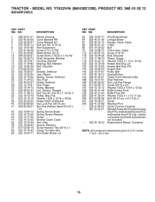
... 532 41 64-05 - - 587 25 33-01 - - 532 43 18-23 Arm Brake Mower Linkage Brake Handle, Clutch Cable V-Belt Bolt Clutch Asm. inches 1 inch = 25.4 mm 15 YTA22V46 (96043021200), PRODUCT NO. 960 43 02 12 MOWER DECK KEY PART NO. Bolt 3/8-16 unc x 2-1/4 Gr. 5 Screw Washout Port ...Quick Connect Coupling Mandrel Assembly (Includes housing (key #14), shaft assembly (key #13), and bearing (key #15) only - RH Keeper Belt Pulley Idler Spring Return Cable...
... 532 41 64-05 - - 587 25 33-01 - - 532 43 18-23 Arm Brake Mower Linkage Brake Handle, Clutch Cable V-Belt Bolt Clutch Asm. inches 1 inch = 25.4 mm 15 YTA22V46 (96043021200), PRODUCT NO. 960 43 02 12 MOWER DECK KEY PART NO. Bolt 3/8-16 unc x 2-1/4 Gr. 5 Screw Washout Port ...Quick Connect Coupling Mandrel Assembly (Includes housing (key #14), shaft assembly (key #13), and bearing (key #15) only - RH Keeper Belt Pulley Idler Spring Return Cable...
Parts Manual
Page 18
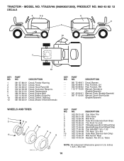
... 581 58 00-01 Decal, Fender Warning Decal, Hood Decal, Hood Panel SD Decal, Customer Respons. PART NO. Tube) NOTE: All component dimensions given in U.S. YTA22V46 (96043021200), PRODUCT NO. 960 43 02 12 DECALS 2 56 2 9 3 1 10 7 12 KEY NO. 1 2 3 5 6 7 9 10 12 PART NO. Decal, Replacement Decal, Engine B&S Decal, Battery Dnge/Poi... 20 x 8-8 Tube Rear (Service Item Only) Rim Asm 8" Rear Sealant, Tire (10 oz. PART NO. inches 1 inch = 25.4 mm 18 MODEL NO. Warning Decal, Mower V-Belt Schematic KEY NO. - - - - - - - - TRACTOR -
... 581 58 00-01 Decal, Fender Warning Decal, Hood Decal, Hood Panel SD Decal, Customer Respons. PART NO. Tube) NOTE: All component dimensions given in U.S. YTA22V46 (96043021200), PRODUCT NO. 960 43 02 12 DECALS 2 56 2 9 3 1 10 7 12 KEY NO. 1 2 3 5 6 7 9 10 12 PART NO. Decal, Replacement Decal, Engine B&S Decal, Battery Dnge/Poi... 20 x 8-8 Tube Rear (Service Item Only) Rim Asm 8" Rear Sealant, Tire (10 oz. PART NO. inches 1 inch = 25.4 mm 18 MODEL NO. Warning Decal, Mower V-Belt Schematic KEY NO. - - - - - - - - TRACTOR -
Operation Manual
Page 6
... tractor, ensure freewheel control is filled with fresh, clean, regular unleaded gasoline. ✓ Become familiar with the instructions that follow all belt keepers. ✓ Check wiring. WARNING: Before starting, read, understand and follow . Correct tire pressure is properly leveled side-to-side...in this manual.) 6 Verify that are routed correctly. CHECK FOR PROPER POSITION OF ALL BELTS See the figures that the belts are shown for replacing motion and mower blade drive belts in the Operation section of controls) • Raise attachment lift lever to -rear for...
... tractor, ensure freewheel control is filled with fresh, clean, regular unleaded gasoline. ✓ Become familiar with the instructions that follow all belt keepers. ✓ Check wiring. WARNING: Before starting, read, understand and follow . Correct tire pressure is properly leveled side-to-side...in this manual.) 6 Verify that are routed correctly. CHECK FOR PROPER POSITION OF ALL BELTS See the figures that the belts are shown for replacing motion and mower blade drive belts in the Operation section of controls) • Raise attachment lift lever to -rear for...
Operation Manual
Page 14
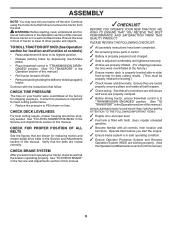
... on this manual. • At least once a year you should replace the spark plug, clean or replace air filter, and check blades and belts for wear. BEFORE EACH USE EVERY 8 HOURS EVERY 25 HOURS EVERY 50 HOURS EVERY 100 HOURS EVERY SEASON BEFORE STORAGE 3 4 5 1,2 1,2 ... Check/Replace Mower Blades C Lubrication Chart T Check Battery Level O Clean Battery and Terminals R Clean Debris off Steering Plate Check Mower Levelness Check V-Belts Check Engine Oil Level Change Engine Oil (models with maintenance-free battery. 1, 2 2 2 5 - Replace blades more often when operating in sandy...
... on this manual. • At least once a year you should replace the spark plug, clean or replace air filter, and check blades and belts for wear. BEFORE EACH USE EVERY 8 HOURS EVERY 25 HOURS EVERY 50 HOURS EVERY 100 HOURS EVERY SEASON BEFORE STORAGE 3 4 5 1,2 1,2 ... Check/Replace Mower Blades C Lubrication Chart T Check Battery Level O Clean Battery and Terminals R Clean Debris off Steering Plate Check Mower Levelness Check V-Belts Check Engine Oil Level Change Engine Oil (models with maintenance-free battery. 1, 2 2 2 5 - Replace blades more often when operating in sandy...

Operation Manual
Page 16
...running low on the drain valve. Pour slowly. Keep oil at "FULL" line on oil fill cap/dipstick for checking level. MAINTENANCE V-BELTS Check V-belts for deterioration and wear after 100 hours of drain valve and install the drain tube onto the fitting. • Unlock drain valve by pushing... careful not to allow dirt to slip from lower dash cover. Change the oil after each time you check the oil level. Replace belts if they will drain more frequently to the bottom fitting of the transaxle. Tighten cap onto the tube securely when finished. 16 TRANSAXLE MAINTENANCE...
...running low on the drain valve. Pour slowly. Keep oil at "FULL" line on oil fill cap/dipstick for checking level. MAINTENANCE V-BELTS Check V-belts for deterioration and wear after 100 hours of drain valve and install the drain tube onto the fitting. • Unlock drain valve by pushing... careful not to allow dirt to slip from lower dash cover. Change the oil after each time you check the oil level. Replace belts if they will drain more frequently to the bottom fitting of the transaxle. Tighten cap onto the tube securely when finished. 16 TRANSAXLE MAINTENANCE...
Operation Manual
Page 17
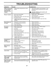
... spark arrester (if equipped) as necessary. CLAMP CLAMP CLEANING • Clean engine, battery, seat, finish, etc. Debris can restrict clutch/brake pedal shaft movement, causing belt slip and loss of engine. CAUTION: Avoid all foreign matter. • Clean debris from "Lower dash cover removal" section of this manual. Use compressed air...
... spark arrester (if equipped) as necessary. CLAMP CLAMP CLEANING • Clean engine, battery, seat, finish, etc. Debris can restrict clutch/brake pedal shaft movement, causing belt slip and loss of engine. CAUTION: Avoid all foreign matter. • Clean debris from "Lower dash cover removal" section of this manual. Use compressed air...

Operation Manual
Page 19
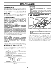
... - TO REMOVE MOWER (See Fig. 22) • Place attachment clutch in "DISENGAGED" position. • Lower attachment lift lever to its lowest position. • Remove mower belt from engine pulley (M). • Remove retainer spring (K), slide collar (L) off and push housing guide (P) out of the lever. • Slide mower out from rear mower...
... - TO REMOVE MOWER (See Fig. 22) • Place attachment clutch in "DISENGAGED" position. • Lower attachment lift lever to its lowest position. • Remove mower belt from engine pulley (M). • Remove retainer spring (K), slide collar (L) off and push housing guide (P) out of the lever. • Slide mower out from rear mower...

Operation Manual
Page 20
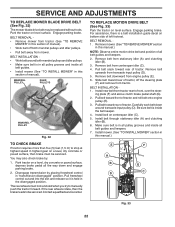
...into bracket, slide collar (L) onto guide and secure with washer and retainer spring. • Repeat on engine pulley (M). Fig. 26 IMPORTANT: CHECK BELT FOR PROPER ROUTING IN ALL MOWER PULLEY GROOVES. • Raise attachment lift lever to highest position. • If necessary, adjust gauge wheels before... operating mower as shown in arm over pin (D) on rear mower bracket and secure with retainer spring (K). • Install belt on opposite side of clutch cable spring (Q) into hole in idler arm (R). • Push clutch cable housing guide (P) into hole in ...
...into bracket, slide collar (L) onto guide and secure with washer and retainer spring. • Repeat on engine pulley (M). Fig. 26 IMPORTANT: CHECK BELT FOR PROPER ROUTING IN ALL MOWER PULLEY GROOVES. • Raise attachment lift lever to highest position. • If necessary, adjust gauge wheels before... operating mower as shown in arm over pin (D) on rear mower bracket and secure with retainer spring (K). • Install belt on opposite side of clutch cable spring (Q) into hole in idler arm (R). • Push clutch cable housing guide (P) into hole in ...
Operation Manual
Page 22
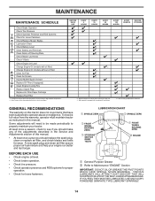
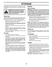
...section of manual). Contact a qualified service center. BELT INSTALLATION 1. Install belt through stationary idler (A) and clutching idler (B). 6. BELT INSTALLATION • Work belt around transaxle input pulley (D). Install belt on level surface. Engage parking brake. BELT REMOVAL • Remove mower from mower. MANDREL ...concrete or paved surface, depress brake pedal all the way down around both mandrel pulleys and idler pulleys. • Pull belt away from tractor (See "TO REMOVE MOWER" in highest gear on a level, dry concrete or paved surface, then ...
...section of manual). Contact a qualified service center. BELT INSTALLATION 1. Install belt through stationary idler (A) and clutching idler (B). 6. BELT INSTALLATION • Work belt around transaxle input pulley (D). Install belt on level surface. Engage parking brake. BELT REMOVAL • Remove mower from mower. MANDREL ...concrete or paved surface, depress brake pedal all the way down around both mandrel pulleys and idler pulleys. • Pull belt away from tractor (See "TO REMOVE MOWER" in highest gear on a level, dry concrete or paved surface, then ...
Operation Manual
Page 25
... carburetor. Store in a clean, dry area. • Clean entire tractor. (See "CLEANING" in the Maintenance section of this manual.) • Inspect and replace belts, if necessary. (See belt replacement instructions in the Service and Adjustments section of this manual.) • Lubricate as needed prior to form and will cause problems. • If...
... carburetor. Store in a clean, dry area. • Clean entire tractor. (See "CLEANING" in the Maintenance section of this manual.) • Inspect and replace belts, if necessary. (See belt replacement instructions in the Service and Adjustments section of this manual.) • Lubricate as needed prior to form and will cause problems. • If...
Operation Manual
Page 27
...half and full speed (fast) position before mowing. 4. See while mower or other attachment is not "ON" 1. Poor cut - Mower drive belt worn. 8. Bulb(s) or lamp(s) burned out. 3. Replace battery. 2. Replace regulator. 4. See "TO REMOVE WHEEL" in the Maintenance section.... level. 3. Wet grass. 3. Tighten blade bolt. 7. Clogged mower deck vent holes from buildup of mower housing. 8. Motion drive belt worn, damaged, or broken. 4. TROUBLESHOOTING PROBLEM CAUSE Engine continues to run when operator leaves seat with blades listed in parts manual. ...
...half and full speed (fast) position before mowing. 4. See while mower or other attachment is not "ON" 1. Poor cut - Mower drive belt worn. 8. Bulb(s) or lamp(s) burned out. 3. Replace battery. 2. Replace regulator. 4. See "TO REMOVE WHEEL" in the Maintenance section.... level. 3. Wet grass. 3. Tighten blade bolt. 7. Clogged mower deck vent holes from buildup of mower housing. 8. Motion drive belt worn, damaged, or broken. 4. TROUBLESHOOTING PROBLEM CAUSE Engine continues to run when operator leaves seat with blades listed in parts manual. ...


