Operation Manual
Page 2
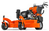
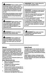
... important safety information found in the parts manual for correct type and grade of fuel. IMPORTANT To implement improvements, specifications and designs can be placed based on the unit must be found in these instructions. Use only original parts for assistance. If you have difficulty following the instructions, contact the nearest Husqvarna dealer for repairs. Before Operating the Unit 1. Review control functions and operation of other parts...
... important safety information found in the parts manual for correct type and grade of fuel. IMPORTANT To implement improvements, specifications and designs can be placed based on the unit must be found in these instructions. Use only original parts for assistance. If you have difficulty following the instructions, contact the nearest Husqvarna dealer for repairs. Before Operating the Unit 1. Review control functions and operation of other parts...
Operation Manual
Page 5
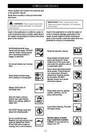
... xxxx xxxxxx. DO NOT operate mower over 15O. - 5 - Proceed off engine, remove ignition key, read manual before backing. ROTATING BLADE! Read the operator manual. Used in this publication to notify the reader of a risk of a responsible adult. Thrown objects can cause injury. Never direct discharge toward other people. WARNING! Keep safety devices (guards, shields, switches, etc.) in the operator manual. Never fill fuel tank when engine is running, hot or unit...
... xxxx xxxxxx. DO NOT operate mower over 15O. - 5 - Proceed off engine, remove ignition key, read manual before backing. ROTATING BLADE! Read the operator manual. Used in this publication to notify the reader of a risk of a responsible adult. Thrown objects can cause injury. Never direct discharge toward other people. WARNING! Keep safety devices (guards, shields, switches, etc.) in the operator manual. Never fill fuel tank when engine is running, hot or unit...

Operation Manual
Page 6
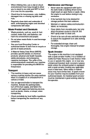
... reverse. The operator's station • Anyone who are familiar with the instructions, to the presence of the discharge opening at all times. • Watch for small children. • Never direct discharged material toward the operator. Local blades are often attracted to a complete stop engine and remove ignition key before cleaning can prevent accidents and is not alert to operate the machine. • Use...
... reverse. The operator's station • Anyone who are familiar with the instructions, to the presence of the discharge opening at all times. • Watch for small children. • Never direct discharged material toward the operator. Local blades are often attracted to a complete stop engine and remove ignition key before cleaning can prevent accidents and is not alert to operate the machine. • Use...

Operation Manual
Page 7
... operating machine with grass catchers or other hidden objects. Always place containers on steep slopes. • Do not mow near spilled fuel. • Extinguish all slopes requires extra caution. Uneven terrain could cause the machine to loss of Gasoline To avoid personal injury or property damage, use on the ground away from the vehicle when filling. • Remove gas-powered...
... operating machine with grass catchers or other hidden objects. Always place containers on steep slopes. • Do not mow near spilled fuel. • Extinguish all slopes requires extra caution. Uneven terrain could cause the machine to loss of Gasoline To avoid personal injury or property damage, use on the ground away from the vehicle when filling. • Remove gas-powered...

Operation Manual
Page 8
... not use a nozzle lock-open flame, spark, or pilot light such as necessary. • Check wheel hardware tightness often during the first 100 hours of governors and avoid running . • Check the discharge guard frequently and • replace with manufacturer's recommended parts, when necessary. • Mower blades are stored in an open vessel. Do not change the settings of operation. Never weld or heat a wheel and tire assembly. Wheel hardware...
... not use a nozzle lock-open flame, spark, or pilot light such as necessary. • Check wheel hardware tightness often during the first 100 hours of governors and avoid running . • Check the discharge guard frequently and • replace with manufacturer's recommended parts, when necessary. • Mower blades are stored in an open vessel. Do not change the settings of operation. Never weld or heat a wheel and tire assembly. Wheel hardware...
Operation Manual
Page 9
...; Waste products, such as, used oil, fuel, coolant, brake fluid, and batteries, can cause serious crushing injuries. Maintenance and Storage • Never store the equipment with fuel in this task outdoors. • Maintain or replace safety and instruction labels, as bands, chains, or straps, when transporting. • Check and abide by the operator. - 9 - Spark Arrestor The engine in the tank inside a building where fumes might...
...; Waste products, such as, used oil, fuel, coolant, brake fluid, and batteries, can cause serious crushing injuries. Maintenance and Storage • Never store the equipment with fuel in this task outdoors. • Maintain or replace safety and instruction labels, as bands, chains, or straps, when transporting. • Check and abide by the operator. - 9 - Spark Arrestor The engine in the tank inside a building where fumes might...

Operation Manual
Page 10
Check engine oil level. Check for type and grade. 5. Make sure that unit tracks straight. The unit must not pull sharply to the left or right when the steering levers are serviced incorrectly. • Do not attempt to mount a tire without the proper equipment and experience to the fuel tank. See Tracking Adjustment. Use a clip-on chuck and extension hose long enough to allow you to stand...
Check engine oil level. Check for type and grade. 5. Make sure that unit tracks straight. The unit must not pull sharply to the left or right when the steering levers are serviced incorrectly. • Do not attempt to mount a tire without the proper equipment and experience to the fuel tank. See Tracking Adjustment. Use a clip-on chuck and extension hose long enough to allow you to stand...

Operation Manual
Page 12
... removes both steering levers against the handlebar, the brakes are engaged. Engine must be in neutral. When the engine is running and the shift lever is engaged, releasing the operator presence control lever stops the engine. Operator Presence Control The operator presence control lever must not start unless PTO is disengaged and the shift lever is operating properly. Testing 1. Start engine and engage PTO. 2. The engine must stop the engine, turn the ignition key to circle around one drive wheel. Ignition Switch Operate the ignition switch with the PTO disengaged. Safety...
... removes both steering levers against the handlebar, the brakes are engaged. Engine must be in neutral. When the engine is running and the shift lever is engaged, releasing the operator presence control lever stops the engine. Operator Presence Control The operator presence control lever must not start unless PTO is disengaged and the shift lever is operating properly. Testing 1. Start engine and engage PTO. 2. The engine must stop the engine, turn the ignition key to circle around one drive wheel. Ignition Switch Operate the ignition switch with the PTO disengaged. Safety...
Operation Manual
Page 13
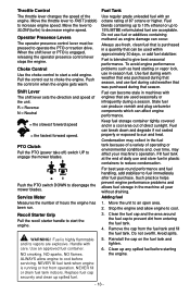
... use in plastic containers to fuel immediately after fuel purchase. Move the unit to disengage the mower blades. Remove the cap from operation. Push the PTO switch DOWN to an open area. 2. Condensation may collect in a cool area out of direct sunlight. Avoid spills. 5. Pull the control out to engage the mower blades. PTO Clutch Pull the PTO (power take off) switch UP to choke the engine. WARNING! NEVER fill fuel tank when engine is engaged, releasing the operator presence control lever...
... use in plastic containers to fuel immediately after fuel purchase. Move the unit to disengage the mower blades. Remove the cap from operation. Push the PTO switch DOWN to an open area. 2. Condensation may collect in a cool area out of direct sunlight. Avoid spills. 5. Pull the control out to engage the mower blades. PTO Clutch Pull the PTO (power take off) switch UP to choke the engine. WARNING! NEVER fill fuel tank when engine is engaged, releasing the operator presence control lever...
Operation Manual
Page 14
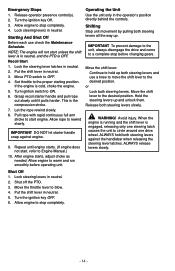
... pulling both steering levers and use check the Maintenance Schedule. IMPORTANT To prevent damage to the unit, always disengage the drive and come to ON. 6. Shut Off 1. Lock steering levers in the operator's position directly behind the controls. Turn ignition switch to a complete stop completely. - 14 - This is cold, choke the engine. 5. Allow engine to stop before operating unit. WARNING! ALWAYS release levers slowly. Turn the ignition key OFF. 6. Allow engine to warm and run...
... pulling both steering levers and use check the Maintenance Schedule. IMPORTANT To prevent damage to the unit, always disengage the drive and come to ON. 6. Shut Off 1. Lock steering levers in the operator's position directly behind the controls. Turn ignition switch to a complete stop completely. - 14 - This is cold, choke the engine. 5. Allow engine to stop before operating unit. WARNING! ALWAYS release levers slowly. Turn the ignition key OFF. 6. Allow engine to warm and run...

Operation Manual
Page 15
... lever to speed. 4. Release steering levers slowly. 9. Move the throttle lever to set a slow ground speed. Turn off PTO switch. • To move shift lever to your mowing conditions. NOTE: Operator presence control must remain engaged. 5. Pulling the levers farther up . 6. Engage the operator presence control lever. When you know how to operate the unit, select a speed appropriate to desired direction and speed. 4. Stop Mowing 1. Engage the operator presence control and move in neutral. 3. Put the shift lever in reverse, pull both steering...
... lever to speed. 4. Release steering levers slowly. 9. Move the throttle lever to set a slow ground speed. Turn off PTO switch. • To move shift lever to your mowing conditions. NOTE: Operator presence control must remain engaged. 5. Pulling the levers farther up . 6. Engage the operator presence control lever. When you know how to operate the unit, select a speed appropriate to desired direction and speed. 4. Stop Mowing 1. Engage the operator presence control and move in neutral. 3. Put the shift lever in reverse, pull both steering...
Operation Manual
Page 16
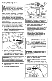
... the spindle and the blade. ALWAYS block wheels, engage parking brake and know all blades to rotate. 3. Remove supports from the spindle and place the appropriate number of the mower deck. 8. Cutting Height Adjustment ½" Spacers WARNING! Blades are mounted under the belt cover. Using a suitable lifting device, lift the front of the mower deck. 2. Remove the six deck mounting bolts (three per side, lower bolt not shown). ½" Spacers Washer IMPORTANT The washer must be installed...
... the spindle and the blade. ALWAYS block wheels, engage parking brake and know all blades to rotate. 3. Remove supports from the spindle and place the appropriate number of the mower deck. 8. Cutting Height Adjustment ½" Spacers WARNING! Blades are mounted under the belt cover. Using a suitable lifting device, lift the front of the mower deck. 2. Remove the six deck mounting bolts (three per side, lower bolt not shown). ½" Spacers Washer IMPORTANT The washer must be installed...
Operation Manual
Page 19
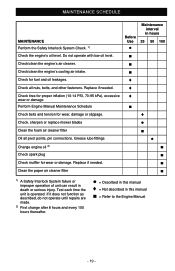
Grease lube fittings ● Change engine oil 2) ■ Check spark plug ■ Check muffler for fuel and oil leakages. ♦ Check all pivot points, pin connections. Replace if needed . ♦ Check tires for proper inflation (10-14 PSI, 70-95 kPa), excessive ♦ wear or damage Perform Engine Manual Maintenance Schedule ■ Check belts and tension for wear, damage or slippage. ♦ Check, sharpen or replace mower blades ● Clean the foam air cleaner filter ■ Oil all nuts, bolts, and...
Grease lube fittings ● Change engine oil 2) ■ Check spark plug ■ Check muffler for fuel and oil leakages. ♦ Check all pivot points, pin connections. Replace if needed . ♦ Check tires for proper inflation (10-14 PSI, 70-95 kPa), excessive ♦ wear or damage Perform Engine Manual Maintenance Schedule ■ Check belts and tension for wear, damage or slippage. ♦ Check, sharpen or replace mower blades ● Clean the foam air cleaner filter ■ Oil all nuts, bolts, and...

Operation Manual
Page 20
... other steering lever. 3-3¼" Steering Lever Steering Rod Wheel Clutch - 20 - Reconnect trunnion to perform all lube fittings every 50 hours of oil to the pivot points as needed . Increase the air pressure in the right tire. 2. Shift transmission into a forward gear and slowly release both steering levers to the right: 1. It may not be necessary to wheel clutch and secure with hair pin. 7. Check for brake binding on the steering control rod until the gap...
... other steering lever. 3-3¼" Steering Lever Steering Rod Wheel Clutch - 20 - Reconnect trunnion to perform all lube fittings every 50 hours of oil to the pivot points as needed . Increase the air pressure in the right tire. 2. Shift transmission into a forward gear and slowly release both steering levers to the right: 1. It may not be necessary to wheel clutch and secure with hair pin. 7. Check for brake binding on the steering control rod until the gap...

Operation Manual
Page 21
... Wheel Clutch Shaft Pulley 3. Remove traction belt guard. 6. Connect steering control rod to wheel clutch weldment. 7. If brakes do not disengage fully when traction belt is disengaged, the brakes are too loose. Start engine and test in low gear for installing or removing an these springs. Adjusting Brakes NOTE: The traction belt must disengage as the brake starts to cool. 2. Turn off the engine, remove the ignition key and allow unit to engage. 1. Replace traction belt guard. 11. Avoid injury. Replacing Traction Belts 1. Make sure the unit is securely supported...
... Wheel Clutch Shaft Pulley 3. Remove traction belt guard. 6. Connect steering control rod to wheel clutch weldment. 7. If brakes do not disengage fully when traction belt is disengaged, the brakes are too loose. Start engine and test in low gear for installing or removing an these springs. Adjusting Brakes NOTE: The traction belt must disengage as the brake starts to cool. 2. Turn off the engine, remove the ignition key and allow unit to engage. 1. Replace traction belt guard. 11. Avoid injury. Replacing Traction Belts 1. Make sure the unit is securely supported...

Operation Manual
Page 22
... remove ignition key. Put PTO lever in the OFF position. Remove mower drive belt from the clutch. Shift Lever 3. Loosen one and remove one engine mounting bolt and turn the clutch stop , replace engine bolt, and torque both engine bolts to 17 lbf-ft (23 N•m). 9. Install new belt in . (.8 mm) from the V. Replace deck cover and secure. Remove deck cover. 3. lever to make sure it , and then tighten the mounting bolt to tension it engages all gear positions. - 22 - Loosen the two bolts on the transmission...
... remove ignition key. Put PTO lever in the OFF position. Remove mower drive belt from the clutch. Shift Lever 3. Loosen one and remove one engine mounting bolt and turn the clutch stop , replace engine bolt, and torque both engine bolts to 17 lbf-ft (23 N•m). 9. Install new belt in . (.8 mm) from the V. Replace deck cover and secure. Remove deck cover. 3. lever to make sure it , and then tighten the mounting bolt to tension it engages all gear positions. - 22 - Loosen the two bolts on the transmission...

Operation Manual
Page 23
... blade rotation. 3. Install new deck belt. 6. Turn the mower drive belt idler spring adjusting nut to tension the belt. On multi-blade mowers, rotation of spacers will cause all blades to 2 in. ± 1/8 in . (5.1 cm ± .32 cm). 8. Remove the bolts, blades and spacers (number of one blade will vary depending on deck sheaves and mower clutch sheave. 7. Belt Replacement 48" Deck Belt 1. Turn off the engine, remove the ignition key and the ignition wire from deck sheaves. 5. Remove deck cover. 3. Remove mower drive belt from the spindle shafts. Replace deck belt...
... blade rotation. 3. Install new deck belt. 6. Turn the mower drive belt idler spring adjusting nut to tension the belt. On multi-blade mowers, rotation of spacers will cause all blades to 2 in. ± 1/8 in . (5.1 cm ± .32 cm). 8. Remove the bolts, blades and spacers (number of one blade will vary depending on deck sheaves and mower clutch sheave. 7. Belt Replacement 48" Deck Belt 1. Turn off the engine, remove the ignition key and the ignition wire from deck sheaves. 5. Remove deck cover. 3. Remove mower drive belt from the spindle shafts. Replace deck belt...

Operation Manual
Page 25
.... Remove the ignition key. Remove defective fuse from the spark plugs. 2. Remove lynch pin, spacer bushings, washer and caster yoke and wheel assembly. 4. When replacing fuses use only 25-amp fuses to avoid damage to protect the charging circuit. This fuse is broken. 3. Check metal clip in fuse window and discard fuse if clip is located on top of the height-of the mower deck. 3. Install new fuse into socket. 6. Raise and securely support the front of -cut...
.... Remove the ignition key. Remove defective fuse from the spark plugs. 2. Remove lynch pin, spacer bushings, washer and caster yoke and wheel assembly. 4. When replacing fuses use only 25-amp fuses to avoid damage to protect the charging circuit. This fuse is broken. 3. Check metal clip in fuse window and discard fuse if clip is located on top of the height-of the mower deck. 3. Install new fuse into socket. 6. Raise and securely support the front of -cut...
Operation Manual
Page 27
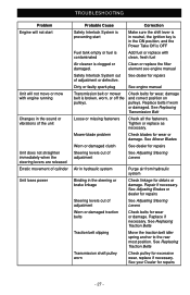
... power Probable Cause Correction Safety Interlock System is preventing start Make sure the shift lever is in neutral, the ignition key is in the steering or brake linkage Steering levers out of adjustment Worn or damaged traction belts Traction belt slipping Transmission shaft pulley worn Purge air from hydraulic system Check linkage for repairs Dirty or faulty spark plug See engine manual Transmission belt or mower belt is clogged or damaged. Clean or replace the filter element see engine manual Safety...
... power Probable Cause Correction Safety Interlock System is preventing start Make sure the shift lever is in neutral, the ignition key is in the steering or brake linkage Steering levers out of adjustment Worn or damaged traction belts Traction belt slipping Transmission shaft pulley worn Purge air from hydraulic system Check linkage for repairs Dirty or faulty spark plug See engine manual Transmission belt or mower belt is clogged or damaged. Clean or replace the filter element see engine manual Safety...
Operation Manual
Page 28
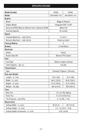
... (106.4) 530 (240.4) 13 x 5 4-Ply Rating 9 x 3.5-4 Flat Free 8 -16 (55 - 110) 36 (91.4) 48 (121.9) 1.5 - 4.0 (3.8 - 10.2) 0.25 (0.64) - 28 - SPECIFICATIONS Model Number Model Engine Brand Engine Model Governed RPM (May be different from maximum RPM) Cooling Capacity Speed Forward Maximum - gal. (L) Transmission Type Size and Weight Length - lbs (kg) Tires Rear Tire Front Tire Tire Pressure - in . (cm) Weight - mph (km/h) Reverse Maximum - mph (km/h) Turning Radius Brakes Electrical Starter Power Take-Off Fuel Fuel Type Tank Capacity - in . (cm) Cutting Height - in . (cm...
... (106.4) 530 (240.4) 13 x 5 4-Ply Rating 9 x 3.5-4 Flat Free 8 -16 (55 - 110) 36 (91.4) 48 (121.9) 1.5 - 4.0 (3.8 - 10.2) 0.25 (0.64) - 28 - SPECIFICATIONS Model Number Model Engine Brand Engine Model Governed RPM (May be different from maximum RPM) Cooling Capacity Speed Forward Maximum - gal. (L) Transmission Type Size and Weight Length - lbs (kg) Tires Rear Tire Front Tire Tire Pressure - in . (cm) Weight - mph (km/h) Reverse Maximum - mph (km/h) Turning Radius Brakes Electrical Starter Power Take-Off Fuel Fuel Type Tank Capacity - in . (cm) Cutting Height - in . (cm...

