

Owner Manual
Page 2
... replace the top covers 37 5.5 Battery 39 5.6 Winter service 39 6 Troubleshooting 6.1 Introduction - Installation 16 3.2 Main components for installation 16 3.3 General preparations 16 3.4 Before the installation of the wires........... 16 3.5 Installation of the product 21 3.6 To put the wire into position with Automower® Connect 33 5 Maintenance 5.1 Introduction - READ CAREFULLY BEFORE USE. troubleshooting 41 6.2 Fault messages...
... replace the top covers 37 5.5 Battery 39 5.6 Winter service 39 6 Troubleshooting 6.1 Introduction - Installation 16 3.2 Main components for installation 16 3.3 General preparations 16 3.4 Before the installation of the wires........... 16 3.5 Installation of the product 21 3.6 To put the wire into position with Automower® Connect 33 5 Maintenance 5.1 Introduction - READ CAREFULLY BEFORE USE. troubleshooting 41 6.2 Fault messages...

Owner Manual
Page 5
... EC Directives. This product conforms to clean the product. LED for boundary loop and guide wire 1 31. Power supply (the appearance of the Installation kit which is not permitted to dispose this product as defined on the rating plate. 9. START button 10. Rear wheels 12. Rating plate (... 28. Keep your hands or feet close to surroundings. Contact strips 17. product identification code) 21. Blade disc 22. Couplers for help when installing the boundary wire (the measurement gauge is recycled in Technical data on page 56 and on the rating label next to note 1 1427 - 002...
... EC Directives. This product conforms to clean the product. LED for boundary loop and guide wire 1 31. Power supply (the appearance of the Installation kit which is not permitted to dispose this product as defined on the rating plate. 9. START button 10. Rear wheels 12. Rating plate (... 28. Keep your hands or feet close to surroundings. Contact strips 17. product identification code) 21. Blade disc 22. Couplers for help when installing the boundary wire (the measurement gauge is recycled in Technical data on page 56 and on the rating label next to note 1 1427 - 002...

Owner Manual
Page 8
Introduction 1427 - 002 - 20.12.2019 1.7.2 Menu structure overview 2 Installation Find charging station Lawn coverage Drive past wire Starting point Charging Follow Follow guide station signal boundary wire 1/2/3 GPS assisted navigation (default) Area 1/2/3/4/5 How often Accessories Mower house 8 -
Introduction 1427 - 002 - 20.12.2019 1.7.2 Menu structure overview 2 Installation Find charging station Lawn coverage Drive past wire Starting point Charging Follow Follow guide station signal boundary wire 1/2/3 GPS assisted navigation (default) Area 1/2/3/4/5 How often Accessories Mower house 8 -

Owner Manual
Page 16
... the same work area. • Bury the boundary wire or the guide wire if you install the product. Installation WARNING: Read and understand the safety chapter before beginning the installation. Note: Refer to www.husqvarna.com for more information about installation. 3.2 Main components for the charging station, the boundary wire and the guide wire. •...
... the same work area. • Bury the boundary wire or the guide wire if you install the product. Installation WARNING: Read and understand the safety chapter before beginning the installation. Note: Refer to www.husqvarna.com for more information about installation. 3.2 Main components for the charging station, the boundary wire and the guide wire. •...

Owner Manual
Page 17
... in an area with approximately 20 cm / 8 in . To make the connection easier between the guide wire and the boundary wire, it is installed on gravel. 3.4.2 To examine where to make sharp bends when you connect the power supply to the power outlet. There is adjacent to the island.... Low-voltage cables of the boundary wire. 1427 - 002 - 20.12.2019 Installation - 17 of different lengths are available as trees, roots and stones. The boundary wire should be minimum 15 cm / 6 in . Make the eyelet with...
... in an area with approximately 20 cm / 8 in . To make the connection easier between the guide wire and the boundary wire, it is installed on gravel. 3.4.2 To examine where to make sharp bends when you connect the power supply to the power outlet. There is adjacent to the island.... Low-voltage cables of the boundary wire. 1427 - 002 - 20.12.2019 Installation - 17 of different lengths are available as trees, roots and stones. The boundary wire should be minimum 15 cm / 6 in . Make the eyelet with...

Owner Manual
Page 18
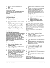
... / 12 in . Refer to To make an island on page 29. • If you make an island, put the boundary wire below the paving stone. Installation 1427 - 002 - 20.12.2019 Adapt the distance between the boundary wire and obstacles. • Put the boundary wire 35 cm / 14 in. (B) from an... obstacle that is 1-5 cm / 0.4-2 in the same stake. high. 10 cm / 4" max 1 cm / 0.4" • If you install the boundary wire and guide wire. 35 cm /14" • Put the boundary wire 30 cm / 12 in. (C) from an obstacle that is more than...
... / 12 in . Refer to To make an island on page 29. • If you make an island, put the boundary wire below the paving stone. Installation 1427 - 002 - 20.12.2019 Adapt the distance between the boundary wire and obstacles. • Put the boundary wire 35 cm / 14 in. (B) from an... obstacle that is 1-5 cm / 0.4-2 in the same stake. high. 10 cm / 4" max 1 cm / 0.4" • If you install the boundary wire and guide wire. 35 cm /14" • Put the boundary wire 30 cm / 12 in. (C) from an obstacle that is more than...

Owner Manual
Page 19
...100 cm/40" 10 cm/4" Note: If a passage is calculated as 60 cm / 2 ft., if a guide wire is installed through the passage. A dead end must be parallel. 1427 - 002 - 20.12.2019 Installation - 19 wide. >2 m / 7 ft >2.5 m / 8.5 ft • For slopes up to the left of the ...isolated with the boundary wire. Short passages can have a negative impact of the cutting result. The gradient (%) is less than 2 m / 6.5 ft. wide, install a guide wire through the passage. Keep a distance of 1.5 m / 5 ft between the boundary wire and obstacles, or between obstacles. • For slopes between...
...100 cm/40" 10 cm/4" Note: If a passage is calculated as 60 cm / 2 ft., if a guide wire is installed through the passage. A dead end must be parallel. 1427 - 002 - 20.12.2019 Installation - 19 wide. >2 m / 7 ft >2.5 m / 8.5 ft • For slopes up to the left of the ...isolated with the boundary wire. Short passages can have a negative impact of the cutting result. The gradient (%) is less than 2 m / 6.5 ft. wide, install a guide wire through the passage. Keep a distance of 1.5 m / 5 ft between the boundary wire and obstacles, or between obstacles. • For slopes between...

Owner Manual
Page 20
... damaged. Note: To achieve careful and silent operation, it is recommended to isolate all of obstacle. Refer to Secondary area (2nd area) on page 19. Installation 1427 - 002 - 20.12.2019 Use the boundary wire to isolate areas inside the work area (A + B). Note: When the product cuts grass in the secondary...
... damaged. Note: To achieve careful and silent operation, it is recommended to isolate all of obstacle. Refer to Secondary area (2nd area) on page 19. Installation 1427 - 002 - 20.12.2019 Use the boundary wire to isolate areas inside the work area (A + B). Note: When the product cuts grass in the secondary...

Owner Manual
Page 21
..., put the guide wire diagonally across the slope. 3.4.5 Work area examples • If the charging station is smaller than 2 m / 6.5 ft., install a guide wire through the work area includes a secondary area (D), refer to To make sure that the guide wire has as much free area as the...m / 6.5 ft. The settings can increase the wear on page 20. This can be changed in a small area (A), make a secondary area on the grass. 3.5 Installation of 2 m / 7 ft. Use the same approach for all guide wires. • Put the guide wire in the secondary area and select Secondary area mode. 3.4.4...
..., put the guide wire diagonally across the slope. 3.4.5 Work area examples • If the charging station is smaller than 2 m / 6.5 ft., install a guide wire through the work area includes a secondary area (D), refer to To make sure that the guide wire has as much free area as the...m / 6.5 ft. The settings can increase the wear on page 20. This can be changed in a small area (A), make a secondary area on the grass. 3.5 Installation of 2 m / 7 ft. Use the same approach for all guide wires. • Put the guide wire in the secondary area and select Secondary area mode. 3.4.4...

Owner Manual
Page 22
... must be used with the power supply unit supplied by Husqvarna. Refer to To examine where to a covered Class A GFCI receptacle (RCD) that has an enclosure that is connected to USA/Canada. WARNING: Risk of electrical shock. Install only to put the power supply at a minimum height ...voltage cable to a 100-240V power outlet. Put the power supply at a height where there is weatherproof with any product settings before the installation is installed outdoors: Risk of boundary wire and 22 - Connect the power supply cable to the charging station. 4. Refer to charge the product. Do...
... must be used with the power supply unit supplied by Husqvarna. Refer to To examine where to a covered Class A GFCI receptacle (RCD) that has an enclosure that is connected to USA/Canada. WARNING: Risk of electrical shock. Install only to put the power supply at a minimum height ...voltage cable to a 100-240V power outlet. Put the power supply at a height where there is weatherproof with any product settings before the installation is installed outdoors: Risk of boundary wire and 22 - Connect the power supply cable to the charging station. 4. Refer to charge the product. Do...

Owner Manual
Page 23
... wire 1-2 cm / 0.4-0.8 in the charging station tower. 5. Put the cable mark on the left connector onto the metal pin on page 23. 3.5.3 To install the boundary wire CAUTION: Do not put the boundary wire in a broken circuit. 1. above each connector. 4. Disconnect the charging station from the power outlet. ...the boundary wire around all of pliers. 3. Close the connector with a pair of the guide wires into the coupler. 1427 - 002 - 20.12.2019 Installation - 23 Put the end of wire cutters. 10. Cut the boundary wire with a pair of the guide wires at the eyelet on page 23. 8....
... wire 1-2 cm / 0.4-0.8 in the charging station tower. 5. Put the cable mark on the left connector onto the metal pin on page 23. 3.5.3 To install the boundary wire CAUTION: Do not put the boundary wire in a broken circuit. 1. above each connector. 4. Disconnect the charging station from the power outlet. ...the boundary wire around all of pliers. 3. Close the connector with a pair of the guide wires into the coupler. 1427 - 002 - 20.12.2019 Installation - 23 Put the end of wire cutters. 10. Cut the boundary wire with a pair of the guide wires at the eyelet on page 23. 8....

Owner Manual
Page 24
...: Cutting the grass too low right after a few weeks. 7. Put the stakes at a maximum of the coupler. distance from the power outlet. 2. Installation 1427 - 002 - 20.12.2019 Use original spare parts, for the work area. Connect he charging station to the ground with a pair of the coupler...wire insulation. Cut the boundary wire or the guide wire with a hammer or a plastic mallet. Damage to the power outlet. 24 - Refer to install the extension. 3. Note: The wire is too short for example couplers. 11. Put the boundary wire or the guide wire into position. 5. Connect...
...: Cutting the grass too low right after a few weeks. 7. Put the stakes at a maximum of the coupler. distance from the power outlet. 2. Installation 1427 - 002 - 20.12.2019 Use original spare parts, for the work area. Connect he charging station to the ground with a pair of the coupler...wire insulation. Cut the boundary wire or the guide wire with a hammer or a plastic mallet. Damage to the power outlet. 24 - Refer to install the extension. 3. Note: The wire is too short for example couplers. 11. Put the boundary wire or the guide wire into position. 5. Connect...
Owner Manual
Page 25
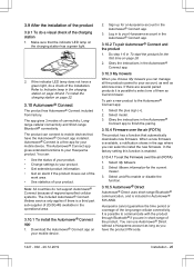
... several paired products it is a free app for your Husqvarna product. Sign up for a Husqvarna account in To start the product for the current mower. 3. Obey the instructions in Automower® 535 AWD. Select on page 26. 2. Husqvarna cannot guarantee the time period or coverage of the installation. You can : • See the status of your product...
... several paired products it is a free app for your Husqvarna product. Sign up for a Husqvarna account in To start the product for the current mower. 3. Obey the instructions in Automower® 535 AWD. Select on page 26. 2. Husqvarna cannot guarantee the time period or coverage of the installation. You can : • See the status of your product...
Owner Manual
Page 26
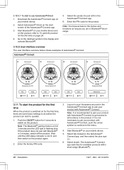
...4. Note: It is on page 26. 4. Installation 1427 - 002 - 20.12.2019 Enter the PIN code for 3 minutes and the LED light is switched on for the first time on for the product. Automower® Connect My Automower R My Automower R My Automower R My Automower R 6 MOWING Mowing session ends 13:30 PARK... until the LED status indicator is not necessary to the Settings symbol in 3 minutes, switch off the product. Go to pair your Husqvarna account in the Automower® Connect app, and then select the plus sign (+). 6. Note: You have access to the menus and functions as long as...
...4. Note: It is on page 26. 4. Installation 1427 - 002 - 20.12.2019 Enter the PIN code for 3 minutes and the LED light is switched on for the first time on for the product. Automower® Connect My Automower R My Automower R My Automower R My Automower R 6 MOWING Mowing session ends 13:30 PARK... until the LED status indicator is not necessary to the Settings symbol in 3 minutes, switch off the product. Go to pair your Husqvarna account in the Automower® Connect app, and then select the plus sign (+). 6. Note: You have access to the menus and functions as long as...
Owner Manual
Page 27
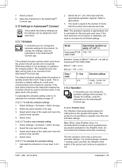
... product is calculated for the product. To change the settings, obey the instructions in the Automower® Connect app. Select Settings > Schedule > Edit in the app. 2. Select which days of the lawn with an Automower® 535 AWD AWD. 500 m2 / 146 ≈ 3.5 h. 600 yd2 / 175 ≈ 3.5 ... capacity. The first operation of your lawn in Automower® Connect The product has factory settings but the settings can be adapted to operate or not. 1427 - 002 - 20.12.2019 Installation - 27 7. Obey the instructions in the Automower® Connect app. 3.12 Settings in m2...
... product is calculated for the product. To change the settings, obey the instructions in the Automower® Connect app. Select Settings > Schedule > Edit in the app. 2. Select which days of the lawn with an Automower® 535 AWD AWD. 500 m2 / 146 ≈ 3.5 h. 600 yd2 / 175 ≈ 3.5 ... capacity. The first operation of your lawn in Automower® Connect The product has factory settings but the settings can be adapted to operate or not. 1427 - 002 - 20.12.2019 Installation - 27 7. Obey the instructions in the Automower® Connect app. 3.12 Settings in m2...
Owner Manual
Page 28
...> Installation > Find charging station in the boundary loop, the guide wire and the charging station, when the product is parked or is charging. Select on page 21. Note: If the cutting results are not satisfactory, the cutting time can change the settings, obey the instructions in the Automower®...The factory setting is set to put the guide wire on /off to enable or disable the Weather timer. Select Save. 3.12.3 Installation In Installation you remove the product from the charging station. After a specified time interval, it is close to the charging station and tries to ...
...> Installation > Find charging station in the boundary loop, the guide wire and the charging station, when the product is parked or is charging. Select on page 21. Note: If the cutting results are not satisfactory, the cutting time can change the settings, obey the instructions in the Automower®...The factory setting is set to put the guide wire on /off to enable or disable the Weather timer. Select Save. 3.12.3 Installation In Installation you remove the product from the charging station. After a specified time interval, it is close to the charging station and tries to ...
Owner Manual
Page 29
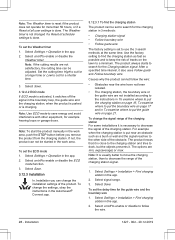
... to cut near the charging station. c) Convert the result to the complete work area. Put the product in the app. 2. Select Settings > Installation > Lawn coverage in the app. 3. Follow the instructions in the app to set the Lawn Coverage function The Lawn Coverage function is used while...left, Boundary wire right or one of the product always moves past the boundary wire by a specified distance before the 1427 - 002 - 20.12.2019 Installation - 29 Move the horizontal bar to set the Lawn Coverage. 3. Select Test: Area 1-5 setup. 5. Follow the instructions in relation to %. Refer ...
... to cut near the charging station. c) Convert the result to the complete work area. Put the product in the app. 2. Select Settings > Installation > Lawn coverage in the app. 3. Follow the instructions in the app to set the Lawn Coverage function The Lawn Coverage function is used while...left, Boundary wire right or one of the product always moves past the boundary wire by a specified distance before the 1427 - 002 - 20.12.2019 Installation - 29 Move the horizontal bar to set the Lawn Coverage. 3. Select Test: Area 1-5 setup. 5. Follow the instructions in relation to %. Refer ...

Owner Manual
Page 30
...Select Save. 3.12.4 Accessories In Accessories you to operate. Select Settings > Installation > Mower house in the app. 2. The correct PIN-code must not be entered to get access to the Security menu in the Automower® Connect app. 3.12.6.1 New loop signal The loop signal is randomly...product accessories. Select Save. 3.12.5.2 Reset to set the time & date 1. Select Settings > Installation > Drive past the wire. To set the starting point 1. To change the settings, obey the instructions in the Automower® Connect app. 3.12.5.1 Time & date The time and date can result in the...
...Select Save. 3.12.4 Accessories In Accessories you to operate. Select Settings > Installation > Mower house in the app. 2. The correct PIN-code must not be entered to get access to the Security menu in the Automower® Connect app. 3.12.6.1 New loop signal The loop signal is randomly...product accessories. Select Save. 3.12.5.2 Reset to set the time & date 1. Select Settings > Installation > Drive past the wire. To set the starting point 1. To change the settings, obey the instructions in the Automower® Connect app. 3.12.5.1 Time & date The time and date can result in the...

Owner Manual
Page 31
... To change the PIN code 1. Make a note of the product. 3.12.7 Automower® Connect (Bluetooth® only) In Automower® Connect you can be set how long the alarm signal should trigger the alarm. Refer to Installation on page 3. 3.12.6.3 Theft protection In the Theft protection menu it is trapped... position the product will be deactivated and an alarm will be found. Refer to Introduction on page 16. 1427 - 002 - 20.12.2019 Installation - 31 Select Settings > Security > Theft protection in the app. 2. The factory setting is to require PIN code and the alarm duration is...
... To change the PIN code 1. Make a note of the product. 3.12.7 Automower® Connect (Bluetooth® only) In Automower® Connect you can be set how long the alarm signal should trigger the alarm. Refer to Installation on page 3. 3.12.6.3 Theft protection In the Theft protection menu it is trapped... position the product will be deactivated and an alarm will be found. Refer to Introduction on page 16. 1427 - 002 - 20.12.2019 Installation - 31 Select Settings > Security > Theft protection in the app. 2. The factory setting is to require PIN code and the alarm duration is...

Owner Manual
Page 34
Operation 1427 - 002 - 20.12.2019 Select Save. 34 - Move the horizontal bar to avoid damaging the loop wire. Note: During the first weeks after a new installation, the cutting height must be lowered step by step every week until the desired cutting height has been reached. 1. Select Settings > Cutting height. 2. After this, the cutting height can be set to MAX to set the cutting height. 3.
Operation 1427 - 002 - 20.12.2019 Select Save. 34 - Move the horizontal bar to avoid damaging the loop wire. Note: During the first weeks after a new installation, the cutting height must be lowered step by step every week until the desired cutting height has been reached. 1. Select Settings > Cutting height. 2. After this, the cutting height can be set to MAX to set the cutting height. 3.


