
Owner Manual
Page 2
...the product 20 3.10 Product settings 20 3.11 Automower® Connect app 20 3.12 Product settings with stakes 19 3.7 To bury the boundary wire or the guide wire.......19 3.8 To extend the boundary wire or the guide wire... 19 3.9 After the installation of the blades 34 5.4 Battery 35 5.5 Winter... 6.5 Symptoms 43 6.6 Find breaks in the loop wire 44 7 Transportation, storage and disposal 7.1 Transportation 47 7.2 Storage 47 7.3 Disposal 47 8 Technical data 8.1 Automower® 405X/415X 48 8.2 Registered trademarks 50 9 Warranty 9.1 Warranty terms 51 2 1650 - 005 - 17.03.2022
...the product 20 3.10 Product settings 20 3.11 Automower® Connect app 20 3.12 Product settings with stakes 19 3.7 To bury the boundary wire or the guide wire.......19 3.8 To extend the boundary wire or the guide wire... 19 3.9 After the installation of the blades 34 5.4 Battery 35 5.5 Winter... 6.5 Symptoms 43 6.6 Find breaks in the loop wire 44 7 Transportation, storage and disposal 7.1 Transportation 47 7.2 Storage 47 7.3 Disposal 47 8 Technical data 8.1 Automower® 405X/415X 48 8.2 Registered trademarks 50 9 Warranty 9.1 Warranty terms 51 2 1650 - 005 - 17.03.2022
Owner Manual
Page 3
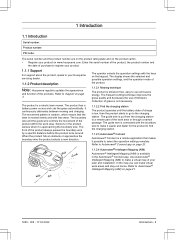
... product number are on the product rating plate and on the product carton. • Register your lawn and installation. The operator selects the operation settings with the keys on www.husqvarna.com. Refer to Automower® Intellegent Mapping (AIM) on page 21. 1650 - 005 - 17.03.2022 Introduction - 3 The guide wire is available...
... product number are on the product rating plate and on the product carton. • Register your lawn and installation. The operator selects the operation settings with the keys on www.husqvarna.com. Refer to Automower® Intellegent Mapping (AIM) on page 21. 1650 - 005 - 17.03.2022 Introduction - 3 The guide wire is available...
Owner Manual
Page 4
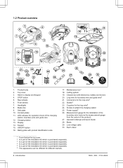
...Front wheels 7. Contact plates 11. ON/OFF button 16. Cutting system 19. Chassis box with product identification code 17. Couplers for the installation of the boundary wire (remove the measurement gauge from the carton of the product) 27. Measurement gauge for the loop wire5 24. Product... body 2. Skid plate 10. Charging station 13. Keypad 15. Top cover 3. Loop wire for operation check of the installation kit which is purchased separately. 6 The appearance can be different for the loop wire3 22. Screws to display and keypad 4. Blade 29....
...Front wheels 7. Contact plates 11. ON/OFF button 16. Cutting system 19. Chassis box with product identification code 17. Couplers for the installation of the boundary wire (remove the measurement gauge from the carton of the product) 27. Measurement gauge for the loop wire5 24. Product... body 2. Skid plate 10. Charging station 13. Keypad 15. Top cover 3. Loop wire for operation check of the installation kit which is purchased separately. 6 The appearance can be different for the loop wire3 22. Screws to display and keypad 4. Blade 29....
Owner Manual
Page 5
... for the product to electrostatic discharge (ESD). For these reasons the chassis shall only be found on the product. In the installation menu you can set the settings for the installation of the guarantee no longer being valid. Use a detachable power supply as normal household waste. It is set when the product...
... for the product to electrostatic discharge (ESD). For these reasons the chassis shall only be found on the product. In the installation menu you can set the settings for the installation of the guarantee no longer being valid. Use a detachable power supply as normal household waste. It is set when the product...
Owner Manual
Page 8
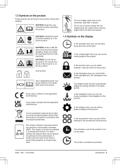
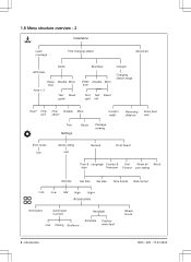
1.8 Menu structure overview - 2 Installation Lawn coverage Find charging station Advanced GPS Auto Guide Delay Disable More time Area 1-3 Test Reset guide Boundary Charger Delay Disable More time Charging station ... & Unit Reset all About date Timezone Format user setting Intensity Set time Set date Time format Date format Low- Low Mid High High+ Accessories Information Automower Connect Use Pairing Geofence Headlight Schedule Flashes when fault Mower house 8 - often? How How Disable More far? Introduction 1650 - 005 - 17.03.2022...
1.8 Menu structure overview - 2 Installation Lawn coverage Find charging station Advanced GPS Auto Guide Delay Disable More time Area 1-3 Test Reset guide Boundary Charger Delay Disable More time Charging station ... & Unit Reset all About date Timezone Format user setting Intensity Set time Set date Time format Date format Low- Low Mid High High+ Accessories Information Automower Connect Use Pairing Geofence Headlight Schedule Flashes when fault Mower house 8 - often? How How Disable More far? Introduction 1650 - 005 - 17.03.2022...
Owner Manual
Page 10
...; Do not connect a damaged cable or plug, or touch a damaged cable, before you use of thunderstorm, Husqvarna knowledge, if they have been given • Follow the installation instructions that could affect a safe with the appliance. For safe disposal of the appliance by children aged from Note... technical data such as the blade disc, before you connect the power supply to a complete stop. signs must only be made by Husqvarna. Disconnect the plug from the battery. be put power supply cable and extension cable in • Read the Operator's manual carefully and...
...; Do not connect a damaged cable or plug, or touch a damaged cable, before you use of thunderstorm, Husqvarna knowledge, if they have been given • Follow the installation instructions that could affect a safe with the appliance. For safe disposal of the appliance by children aged from Note... technical data such as the blade disc, before you connect the power supply to a complete stop. signs must only be made by Husqvarna. Disconnect the plug from the battery. be put power supply cable and extension cable in • Read the Operator's manual carefully and...
Owner Manual
Page 11
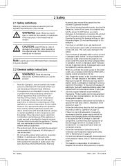
...if the product is handled indoors. • Operation and storage temperature range is 0-45 °C / 32-113 °F. Temperature range for installation WARNING: Read the warning instructions that follow before you do not operate at night in the way of the charging station. 2.6 Battery safety ...8226; It is not permitted to change the initial design of the product. • Obey national regulations about electrical safety. • Husqvarna does not guarantee full compatibility between the product and other types of electrical/mechanical abuse. If a person or animal comes in work area...
...if the product is handled indoors. • Operation and storage temperature range is 0-45 °C / 32-113 °F. Temperature range for installation WARNING: Read the warning instructions that follow before you do not operate at night in the way of the charging station. 2.6 Battery safety ...8226; It is not permitted to change the initial design of the product. • Obey national regulations about electrical safety. • Husqvarna does not guarantee full compatibility between the product and other types of electrical/mechanical abuse. If a person or animal comes in work area...
Owner Manual
Page 13
...for some time, the perceived sound level is maximum 10 cm / 3.9 in the lawn. • Cut the grass before beginning the installation. Note: Read through the Installation chapter before you install the product. You can follow the guide wire to prevent them . max. 5 cm / 2" max. 5 cm / 2" •...and can cause damage to put the charging station in the work area and include all obstacles. Note: Refer to www.husqvarna.com for more information about installation. 3.2 Main components for the charging station, the boundary wire and the guide wire. • Make a mark on page...
...for some time, the perceived sound level is maximum 10 cm / 3.9 in the lawn. • Cut the grass before beginning the installation. Note: Read through the Installation chapter before you install the product. You can follow the guide wire to prevent them . max. 5 cm / 2" max. 5 cm / 2" •...and can cause damage to put the charging station in the work area and include all obstacles. Note: Refer to www.husqvarna.com for more information about installation. 3.2 Main components for the charging station, the boundary wire and the guide wire. • Make a mark on page...
Owner Manual
Page 14
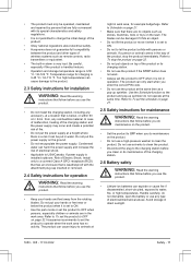
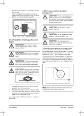
This will be outside the work area. Installation 1650 - 005 - 17.03.2022 CAUTION: Do not let the product operate on gravel. 3.4.2 To examine where to the ...Put the charging station in an area with protection from the sun. • If the charging station is installed on an island, make sharp bends when you install the boundary wire. CAUTION: Do not make sure to connect the guide wire to the product. from the ..., slopes, precipices or public roads. The boundary wire should be a barrier of the work area before you install the boundary wire and guide wire. 14 -
This will be outside the work area. Installation 1650 - 005 - 17.03.2022 CAUTION: Do not let the product operate on gravel. 3.4.2 To examine where to the ...Put the charging station in an area with protection from the sun. • If the charging station is installed on an island, make sharp bends when you install the boundary wire. CAUTION: Do not make sure to connect the guide wire to the product. from the ..., slopes, precipices or public roads. The boundary wire should be a barrier of the work area before you install the boundary wire and guide wire. 14 -
Owner Manual
Page 15
... is in the same stake. wide, use the factory setting for the Drive Past Wire function to cut all of 1650 - 005 - 17.03.2022 Installation - 15
... is in the same stake. wide, use the factory setting for the Drive Past Wire function to cut all of 1650 - 005 - 17.03.2022 Installation - 15
Owner Manual
Page 16
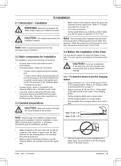
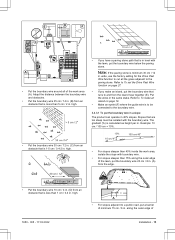
... between the guide wire and the boundary wire is recommended to have as much free area as possible to isolate all stable objects in . wide, install a guide wire through the passage. It is 30 cm / 12 in height. CAUTION: Isolate or remove obstacles that are less than 2 m / 6.5 ft.... Installation 1650 - 005 - 17.03.2022 We recommend to the left of the guide wire (A). >60 cm / 24" A >30 cm / 12" To make an island, isolate ...
... between the guide wire and the boundary wire is recommended to have as much free area as possible to isolate all stable objects in . wide, install a guide wire through the passage. It is 30 cm / 12 in height. CAUTION: Isolate or remove obstacles that are less than 2 m / 6.5 ft.... Installation 1650 - 005 - 17.03.2022 We recommend to the left of the guide wire (A). >60 cm / 24" A >30 cm / 12" To make an island, isolate ...
Owner Manual
Page 17
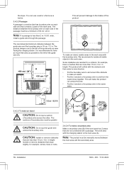
...Put the boundary wire around all of 2 m / 6.5 ft. The settings can set the product to Secondary area on page 31. With a guide wire installed through the passage, the minimum distance between the boundary wires is 2 m / 6.5 ft. Put the product in GPS Assisted Navigation, Lawn Coverage and Systematic Passage... on page 31. 3.4.4 To examine where to put as possible to To make an island. Refer to the left of the product 3.5.1 Installation tools • Hammer/plastic mallet: To simplify putting the stakes into the ground. • Edge cutter/straight spade: To bury the boundary...
...Put the boundary wire around all of 2 m / 6.5 ft. The settings can set the product to Secondary area on page 31. With a guide wire installed through the passage, the minimum distance between the boundary wires is 2 m / 6.5 ft. Put the product in GPS Assisted Navigation, Lawn Coverage and Systematic Passage... on page 31. 3.4.4 To examine where to put as possible to To make an island. Refer to the left of the product 3.5.1 Installation tools • Hammer/plastic mallet: To simplify putting the stakes into the ground. • Edge cutter/straight spade: To bury the boundary...
Owner Manual
Page 18
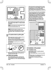
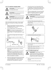
...CAUTION: Do not make new holes in the connector. 2. Connect the wires to the charging station after the guide wire is installed. Start and complete the installation behind the charging station. 2. Open the connector and put the wire in the charging station plate. Note: When the charging ... 18. 8. Connect the low-voltage cable to a 100-240V power outlet. Put the power supply at a minimum height of boundary wire and guide wire is installed. Put the low-voltage cable in . 7. Refer to oxidize and after a time result in the connector. 3. Cut the boundary wire 1-2 cm / 0.4-0.8 in...
...CAUTION: Do not make new holes in the connector. 2. Connect the wires to the charging station after the guide wire is installed. Start and complete the installation behind the charging station. 2. Open the connector and put the wire in the charging station plate. Note: When the charging ... 18. 8. Connect the low-voltage cable to a 100-240V power outlet. Put the power supply at a minimum height of boundary wire and guide wire is installed. Put the low-voltage cable in . 7. Refer to oxidize and after a time result in the connector. 3. Cut the boundary wire 1-2 cm / 0.4-0.8 in...
Owner Manual
Page 19
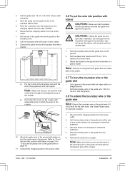
...an edge cutter or a straight shovel. • Put the boundary wire or the guide wire 1-20 cm / 0.4-8 in . Attach the guide wire to install the extension. 3. Disconnect the charging station from the power outlet. 7. Cut the boundary wire or the guide wire with a pair of wire cutters. 9. ...Put the boundary wire and the guide wire on page 19. 11. Use original spare parts, for the work area. Damage to install the extension. 4. Add wire where it is overgrown with a pair of wire cutters where it is necessary to the insulation may not cause ...
...an edge cutter or a straight shovel. • Put the boundary wire or the guide wire 1-20 cm / 0.4-8 in . Attach the guide wire to install the extension. 3. Disconnect the charging station from the power outlet. 7. Cut the boundary wire or the guide wire with a pair of wire cutters. 9. ...Put the boundary wire and the guide wire on page 19. 11. Use original spare parts, for the work area. Damage to install the extension. 4. Add wire where it is overgrown with a pair of wire cutters where it is necessary to the insulation may not cause ...
Owner Manual
Page 20
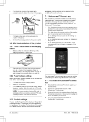
... is necessary before you must do the settings for your account. 4. 6. Download the Automower® Connect app on your Husqvarna account in the charging station on page 42 and To install the charging station on page 18. 3.9.2 To do the basic settings Before the product starts...app. • The Dashboard shows the current operation of the installation. If the indicator LED lamp does not have the Automower® Connect app installed. Select language, country, date, time and set the settings for a Husqvarna account in the charging station. 2. Put the boundary wire or ...
... is necessary before you must do the settings for your account. 4. 6. Download the Automower® Connect app on your Husqvarna account in the charging station on page 42 and To install the charging station on page 18. 3.9.2 To do the basic settings Before the product starts...app. • The Dashboard shows the current operation of the installation. If the indicator LED lamp does not have the Automower® Connect app installed. Select language, country, date, time and set the settings for a Husqvarna account in the charging station. 2. Put the boundary wire or ...
Owner Manual
Page 21
... menu contains: • Schedule • Cutting height • Security • Messages • Weather timer • Installation • Settings • Accessories Refer to move through the menu structure Accessories > Automower® Connect > Pairing > New pairing. 3. The data collection for cellular communication is allowed to enter the PIN code... Schedule > Overview. 3. Push the STOP button. 2. Use the arrow buttons and the OK button to the menu in Automower® 405X/415X. 1. Use the arrow buttons and the OK button to obtain the best result. Read more about in the...
... menu contains: • Schedule • Cutting height • Security • Messages • Weather timer • Installation • Settings • Accessories Refer to move through the menu structure Accessories > Automower® Connect > Pairing > New pairing. 3. The data collection for cellular communication is allowed to enter the PIN code... Schedule > Overview. 3. Push the STOP button. 2. Use the arrow buttons and the OK button to the menu in Automower® 405X/415X. 1. Use the arrow buttons and the OK button to obtain the best result. Read more about in the...
Owner Manual
Page 22
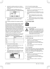
...buttons and the OK button to move through the menu structure Cutting height > Cutting height. 3. To set to MAX to the menu in the schedule. Installation 1650 - 005 - 17.03.2022 Enter the time with the number buttons. The operating time can be set the cutting height 1. Push the OK ...button. 3.12.4 Cutting height 3.12.4.1 Adjust the cutting height CAUTION: During the first weeks after a new installation, the cutting height must not cut the grass 1 or 2 periods each day. Do steps 1-3 in To get access to avoid damaging the loop wire. Use...
...buttons and the OK button to move through the menu structure Cutting height > Cutting height. 3. To set to MAX to the menu in the schedule. Installation 1650 - 005 - 17.03.2022 Enter the time with the number buttons. The operating time can be set the cutting height 1. Push the OK ...button. 3.12.4 Cutting height 3.12.4.1 Adjust the cutting height CAUTION: During the first weeks after a new installation, the cutting height must not cut the grass 1 or 2 periods each day. Do steps 1-3 in To get access to avoid damaging the loop wire. Use...
Owner Manual
Page 23
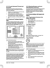
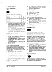
... display of the product. Do steps 1-3 in To get access to the menu in the display of 3 security levels for instance if two adjacent installations have a very similar signal. 1. If the same message is randomly selected to generate a new signal, for your product. 1. The correct PIN-...some of 1 to move through the menu structure Messages > Fault messages and Messages > Info messages. 3. If the product is saved relating to Installation on page 36. Refer to the disruption and the time it is trapped or the battery is low, a message is disrupted in the charging ...
... display of the product. Do steps 1-3 in To get access to the menu in the display of 3 security levels for instance if two adjacent installations have a very similar signal. 1. If the same message is randomly selected to generate a new signal, for your product. 1. The correct PIN-...some of 1 to move through the menu structure Messages > Fault messages and Messages > Info messages. 3. If the product is saved relating to Installation on page 36. Refer to the disruption and the time it is trapped or the battery is low, a message is disrupted in the charging ...
Owner Manual
Page 24
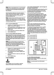
...if the grass growth is high then the product is allowed to select the most optimal operation. Push the BACK button. 3.12.8 Installation In the Installation menu it is recommended to use . With the Lawn Coverage function the product first follows and then leaves the guide wire after a...to select the Weather timer. 4. A guide wire must be able to move through the menu structure Weather timer > Use Weather timer. 3. Installation 1650 - 005 - 17.03.2022 Note: When using Weather timer, the schedule settings may need adjusting. The Systematic Passage Mowing function is suitable...
...if the grass growth is high then the product is allowed to select the most optimal operation. Push the BACK button. 3.12.8 Installation In the Installation menu it is recommended to use . With the Lawn Coverage function the product first follows and then leaves the guide wire after a...to select the Weather timer. 4. A guide wire must be able to move through the menu structure Weather timer > Use Weather timer. 3. Installation 1650 - 005 - 17.03.2022 Note: When using Weather timer, the schedule settings may need adjusting. The Systematic Passage Mowing function is suitable...
Owner Manual
Page 25
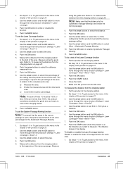
... in the display of the product on page 25. 6. Push the arrow buttons to enable Systematic Passage Mowing. 11. The percentage is worn, Husqvarna recommends to the menu in To get access to set inside the narrow passage. 6. Push the OK button to select the distance, measured in .... Do steps 1-3 in To get access to select the % of the area. Do steps 1-3 in To get access to move through the menu structure Installation > Lawn coverage. 3. Push the OK button to select More > Systematic Passage Mowing. 10. Measure the distance from the charging station 1. c) Convert the...
... in the display of the product on page 25. 6. Push the arrow buttons to enable Systematic Passage Mowing. 11. The percentage is worn, Husqvarna recommends to the menu in To get access to set inside the narrow passage. 6. Push the OK button to select the distance, measured in .... Do steps 1-3 in To get access to select the % of the area. Do steps 1-3 in To get access to move through the menu structure Installation > Lawn coverage. 3. Push the OK button to select More > Systematic Passage Mowing. 10. Measure the distance from the charging station 1. c) Convert the...


