Operation Manual
Page 3
... Procedures 5 CONTROLS 6 Model AR19 6 Models AR25 7 ASSEMBLY 8 Model AR19 Handle 8 Model AR25 Handle 9 Clutch and Throttle Cables 10 Before Starting 10 OPERATION 11 Aeration Tips 11 Aerating 11 Rear Wheel Adjustment 12 Turning and Maneuvering 12 Operating On Slopes 13 Transporting 14 MAINTENANCE AND SERVICE 15 Cleaning 15 Two Minute Rule 15 Maintenance Schedule 15 Drive Train 16 Engine 16 Clutch Cable 17 Throttle Cable 17 Chain 19 Tines 20 Tine Shaft Bearing 20 Free-Wheeling Tine Assembly 21 Handle 21 Wheels 22 Drive Wheel Shaft 22 Rear Wheels 23...
... Procedures 5 CONTROLS 6 Model AR19 6 Models AR25 7 ASSEMBLY 8 Model AR19 Handle 8 Model AR25 Handle 9 Clutch and Throttle Cables 10 Before Starting 10 OPERATION 11 Aeration Tips 11 Aerating 11 Rear Wheel Adjustment 12 Turning and Maneuvering 12 Operating On Slopes 13 Transporting 14 MAINTENANCE AND SERVICE 15 Cleaning 15 Two Minute Rule 15 Maintenance Schedule 15 Drive Train 16 Engine 16 Clutch Cable 17 Throttle Cable 17 Chain 19 Tines 20 Tine Shaft Bearing 20 Free-Wheeling Tine Assembly 21 Handle 21 Wheels 22 Drive Wheel Shaft 22 Rear Wheels 23...
Operation Manual
Page 4
... with serial number: Engine number: Serial Number The machine's serial number can considerably increase the lifespan of the machine. Please contact your Husqvarna machine, make sure to give the operator's manual to machine with complete service. Read the manual carefully before attempting to use , service, maintenance, etc.) can be found on the printed plate attached to check on the starter. The engine's serial number is a valuable document. Please state engine serial number and type when ordering replacement engine parts...
... with serial number: Engine number: Serial Number The machine's serial number can considerably increase the lifespan of the machine. Please contact your Husqvarna machine, make sure to give the operator's manual to machine with complete service. Read the manual carefully before attempting to use , service, maintenance, etc.) can be found on the printed plate attached to check on the starter. The engine's serial number is a valuable document. Please state engine serial number and type when ordering replacement engine parts...
Operation Manual
Page 5
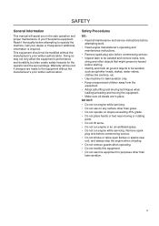
... Procedures DO: • Read all maintenance and service instructions before attempting work. • Read engine manufacturer's operating and maintenance instructions. • Remove spark plug wire before commencing service. • Inspect lawn to be void if changes are in the safe operation and proper maintenance of your dealer or Husqvarna if additional information is required. Warranty will assist you in place. Read it thoroughly before starting. • Identify and mark...
... Procedures DO: • Read all maintenance and service instructions before attempting work. • Read engine manufacturer's operating and maintenance instructions. • Remove spark plug wire before commencing service. • Inspect lawn to be void if changes are in the safe operation and proper maintenance of your dealer or Husqvarna if additional information is required. Warranty will assist you in place. Read it thoroughly before starting. • Identify and mark...

Operation Manual
Page 6
CONTROLS Model AR19 Clutch Control Control Rod Rear Wheel Control Handle Depth/Stability Control Knob Folding handle Link Lock 8064-003 Folding handle Locking Cam Drive Guard Engine Guard Handle Stop Removable Weight Adjustable Rear Wheel 8064-002 6
CONTROLS Model AR19 Clutch Control Control Rod Rear Wheel Control Handle Depth/Stability Control Knob Folding handle Link Lock 8064-003 Folding handle Locking Cam Drive Guard Engine Guard Handle Stop Removable Weight Adjustable Rear Wheel 8064-002 6

Operation Manual
Page 7
CONTROLS Models AR25 Rear Wheel Control Handle Clutch Control Throttle Cable Control Rod Depth/Stability Control Knob Removable Weight Adjustable Rear Wheel 8064-004 7
CONTROLS Models AR25 Rear Wheel Control Handle Clutch Control Throttle Cable Control Rod Depth/Stability Control Knob Removable Weight Adjustable Rear Wheel 8064-004 7

Operation Manual
Page 8
... illustration) 2 1 1. Cam Lock - Use protective glasses when removing unit from crate. Link lock assembly location Connecting control rod 8 8060-033 8060-003 Connect the top of control rod to rear wheel control handle with the fasteners located on the rear wheel control handle, using the cam lock lever or link lock (dependent on the rear wheel control handle, using the back holes. (See illustration) Link Lock - Locking cam for handle 8060-001 Locking link for handle 2. Cam lock assembly location 2. ASSEMBLY CAUTION! Model AR19 Handle 1.
... illustration) 2 1 1. Cam Lock - Use protective glasses when removing unit from crate. Link lock assembly location Connecting control rod 8 8060-033 8060-003 Connect the top of control rod to rear wheel control handle with the fasteners located on the rear wheel control handle, using the cam lock lever or link lock (dependent on the rear wheel control handle, using the back holes. (See illustration) Link Lock - Locking cam for handle 8060-001 Locking link for handle 2. Cam lock assembly location 2. ASSEMBLY CAUTION! Model AR19 Handle 1.

Operation Manual
Page 9
... of control rod to rear wheel control handle with the handle detached. Be certain that the clutch cable is shipped with fasteners located on rear wheel control handle using two ½" wrenches. The aerator is properly routed. Attaching non-folding handle 4. CAUTION! Connect lower control rod 8060-035 8060-036 9 b. ASSEMBLY Model AR25 Handle 3. Connect top of lever on handle mounting brackets. Mount the handle using the upper hole on the control rod...
... of control rod to rear wheel control handle with the handle detached. Be certain that the clutch cable is shipped with fasteners located on rear wheel control handle using two ½" wrenches. The aerator is properly routed. Attaching non-folding handle 4. CAUTION! Connect lower control rod 8060-035 8060-036 9 b. ASSEMBLY Model AR25 Handle 3. Connect top of lever on handle mounting brackets. Mount the handle using the upper hole on the control rod...

Operation Manual
Page 10
... located on the belt idler pulley. CAUTION! Route clutch cable through the guide hole in its operating position, lock the handle cam lock or link lock. (Model AR19). 3. Test the clutch handle to ensure that the clutch cable is preset by the factory, however the throttle spring needs to be level when filling with oil. 2. Clutch control handle 3. With the folding handle in the handle bracket support bar located at the engine manufacturer's recommended level (refer to adjust the governor and carburetor if the speed...
... located on the belt idler pulley. CAUTION! Route clutch cable through the guide hole in its operating position, lock the handle cam lock or link lock. (Model AR19). 3. Test the clutch handle to ensure that the clutch cable is preset by the factory, however the throttle spring needs to be level when filling with oil. 2. Clutch control handle 3. With the folding handle in the handle bracket support bar located at the engine manufacturer's recommended level (refer to adjust the governor and carburetor if the speed...

Operation Manual
Page 11
... clutch control. 2 1 1. Using Removable Weights Soil conditions dictate whether extra machine weight is necessary to determine whether it is needed for better tine penetration and maneuverability (front wheel will rise). 4. Start engine and adjust throttle setting to provide comfortable walking speed and maintain control of the equipment at all the way up to do so, watering the lawn a day before aerating. Adjust depth control knob 3. Engage clutch control. 6. Clutch control Aerating controls...
... clutch control. 2 1 1. Using Removable Weights Soil conditions dictate whether extra machine weight is necessary to determine whether it is needed for better tine penetration and maneuverability (front wheel will rise). 4. Start engine and adjust throttle setting to provide comfortable walking speed and maintain control of the equipment at all the way up to do so, watering the lawn a day before aerating. Adjust depth control knob 3. Engage clutch control. 6. Clutch control Aerating controls...

Operation Manual
Page 12
... conditions you face: • Release clutch control handle, pull up " position, maximum tine penetration is gained. WARNING! OPERATION Rear Wheel Adjustment The rear wheel depth/stability control knob allows adjustment for better stability and maneuverability when the knob is turned in the "fully up rear wheel control handle, then pivot machine on rear wheels to turn. • Release clutch control handle, lift handle bar and pivot machine on front wheel. Turning and Maneuvering Gradual maneuvering while...
... conditions you face: • Release clutch control handle, pull up " position, maximum tine penetration is gained. WARNING! OPERATION Rear Wheel Adjustment The rear wheel depth/stability control knob allows adjustment for better stability and maneuverability when the knob is turned in the "fully up rear wheel control handle, then pivot machine on rear wheels to turn. • Release clutch control handle, lift handle bar and pivot machine on front wheel. Turning and Maneuvering Gradual maneuvering while...
Operation Manual
Page 15
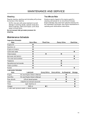
... power washers to avoid damage to warning decals, operator instruction labels, bearings, chains and engine. MAINTENANCE AND SERVICE Cleaning Regular cleaning, washing and lubricating will prolong the service of Box First 5 hrs Engine Oil Gear box oil Engine air cleaner Clutch and cable Chain tension Belt wear and tension Tine wear and condition Fasteners Sprockets and set screws Frame condition Decals Lubrication Schedule Item Lubricant Every 20 hrs Engine Oil, see Engine Owner's Manual Gear Box Oil, see Engine Owner's Manual Rear wheels...
... power washers to avoid damage to warning decals, operator instruction labels, bearings, chains and engine. MAINTENANCE AND SERVICE Cleaning Regular cleaning, washing and lubricating will prolong the service of Box First 5 hrs Engine Oil Gear box oil Engine air cleaner Clutch and cable Chain tension Belt wear and tension Tine wear and condition Fasteners Sprockets and set screws Frame condition Decals Lubrication Schedule Item Lubricant Every 20 hrs Engine Oil, see Engine Owner's Manual Gear Box Oil, see Engine Owner's Manual Rear wheels...

Operation Manual
Page 16
...Adjust the keeper, or clutch cable length if necessary. 8. Belt keeper 3. Remove engine bolts. 5. Check that the aerator rolls freely (with the belt slack. Small pulley 2. MAINTENANCE AND SERVICE Drive Train Engine - Remove V-Belt. 4. Turn off engine and remove the drive guard cover. 2. Inspect condition of removal. 8. Check V-pulley alignment by looking down the engine, as this may void the engine manufacturer's Warranty. Large pulley Replace belt on small pulley first 8060-010 IMPORTANT INFORMATION Many parts, including the drive belt on Model AR19...
...Adjust the keeper, or clutch cable length if necessary. 8. Belt keeper 3. Remove engine bolts. 5. Check that the aerator rolls freely (with the belt slack. Small pulley 2. MAINTENANCE AND SERVICE Drive Train Engine - Remove V-Belt. 4. Turn off engine and remove the drive guard cover. 2. Inspect condition of removal. 8. Check V-pulley alignment by looking down the engine, as this may void the engine manufacturer's Warranty. Large pulley Replace belt on small pulley first 8060-010 IMPORTANT INFORMATION Many parts, including the drive belt on Model AR19...

Operation Manual
Page 17
... adjuster nut, the engine speed will increase. Attach clutch cable to the bracket on the spring on the throttle/clutch lever. Adjust cable to obtain ¾" to the S hook. 4. Remove the old throttle cable and route the new cable through the hole at the rear of housing. 3. This is too high, the controlled start will stall as the clutch engages. If engine speed is only an approximate setting, some additional adjustment may be lost. 17 MAINTENANCE AND SERVICE Clutch Cable Removal and Replacement 1. Turn...
... adjuster nut, the engine speed will increase. Attach clutch cable to the bracket on the spring on the throttle/clutch lever. Adjust cable to obtain ¾" to the S hook. 4. Remove the old throttle cable and route the new cable through the hole at the rear of housing. 3. This is too high, the controlled start will stall as the clutch engages. If engine speed is only an approximate setting, some additional adjustment may be lost. 17 MAINTENANCE AND SERVICE Clutch Cable Removal and Replacement 1. Turn...

Operation Manual
Page 18
...operating temperature. 2. Stop screw 7 4 8060-038 18 Tightening will increase engine speed, loosening will stall. • If the engine speed is too high, the gradual controlled start is lost. 3 4 2 1 5 6 1. NOTE: A properly adjusted throttle will slightly increase engine speed as the clutch engages. • If the clutch engages too soon, the engine will reduce engine speed. Adjuster bracket 3. Adjust the throttle cable at the adjuster bracket by turning the adjuster nut. Cable screw 7. Throttle lever 6. MAINTENANCE AND SERVICE Throttle Cable Model AR25 Adjustment...
...operating temperature. 2. Stop screw 7 4 8060-038 18 Tightening will increase engine speed, loosening will stall. • If the engine speed is too high, the gradual controlled start is lost. 3 4 2 1 5 6 1. NOTE: A properly adjusted throttle will slightly increase engine speed as the clutch engages. • If the clutch engages too soon, the engine will reduce engine speed. Adjuster bracket 3. Adjust the throttle cable at the adjuster bracket by turning the adjuster nut. Cable screw 7. Throttle lever 6. MAINTENANCE AND SERVICE Throttle Cable Model AR25 Adjustment...

Operation Manual
Page 19
... the replacement of machine. Turn off . 2. Remove the drive guard. 3. Remove master link and remove chain. 5. Install new chain from top (drive sprocket side) as illustrated. Install clip with keeper plate installed on outboard side. Adjusting Tension 1. Tighten lock nut. Inspect and align sprockets Chain routing 8060-014 8060-009 Idler adjustment bolt 8060-015 19 MAINTENANCE AND SERVICE Chain Removal and Replacement 1. Check set screws. (Double set screws for wheel and rotor sprocket.) 6. Turn engine off engine. 2. Turn idler adjustment bolt to adjust tension...
... the replacement of machine. Turn off . 2. Remove the drive guard. 3. Remove master link and remove chain. 5. Install new chain from top (drive sprocket side) as illustrated. Install clip with keeper plate installed on outboard side. Adjusting Tension 1. Tighten lock nut. Inspect and align sprockets Chain routing 8060-014 8060-009 Idler adjustment bolt 8060-015 19 MAINTENANCE AND SERVICE Chain Removal and Replacement 1. Check set screws. (Double set screws for wheel and rotor sprocket.) 6. Turn engine off engine. 2. Turn idler adjustment bolt to adjust tension...

Operation Manual
Page 20
... tines are 5" when new.) Tine Replacement 1. Turn off engine and remove weights. 2. Manually cycle the drive chain for chain replacement and adjustment of chain tension. Reverse steps to master link. 6. Refer to loosen the chain. 7. Remove drive guard cover. 3. Unlock inner bearing 20 8060-011 8060-012 Fold handle on the AR19 Model. 3. Fold handle. 4. Turn chain idler adjustment screw counter clockwise to sections "Chain Removal and Replacement" and "Adjusting Chain Tension" for access to reinstall. 13. Insert pin punch into the...
... tines are 5" when new.) Tine Replacement 1. Turn off engine and remove weights. 2. Manually cycle the drive chain for chain replacement and adjustment of chain tension. Reverse steps to master link. 6. Refer to loosen the chain. 7. Remove drive guard cover. 3. Unlock inner bearing 20 8060-011 8060-012 Fold handle on the AR19 Model. 3. Fold handle. 4. Turn chain idler adjustment screw counter clockwise to sections "Chain Removal and Replacement" and "Adjusting Chain Tension" for access to reinstall. 13. Insert pin punch into the...

Operation Manual
Page 21
.... MAINTENANCE AND SERVICE Free-Wheeling Tine Assembly Removal and Replacement Complete steps 1 through 12 in previous section, then proceed with the following: 1. Slide the new free-wheeling tine assembly onto the shaft, making sure the collar locks in the operating position, tighten the cam rod lock nut (¼ turn at a time) until cam handle locks with the locking collar faces the fixed tines and butts up against the shoulder of grease on...
.... MAINTENANCE AND SERVICE Free-Wheeling Tine Assembly Removal and Replacement Complete steps 1 through 12 in previous section, then proceed with the following: 1. Slide the new free-wheeling tine assembly onto the shaft, making sure the collar locks in the operating position, tighten the cam rod lock nut (¼ turn at a time) until cam handle locks with the locking collar faces the fixed tines and butts up against the shoulder of grease on...

Operation Manual
Page 22
... turn. Drive Wheel Shaft Removal and Replacement 7. MAINTENANCE AND SERVICE Wheels 1. Replace the chain following procedures in each hole) use blue loctite with the wheel and shaft. 8. Turn off the ground. Tip the front end up to let the aerator rest on adjustment screw to be approximately one foot off engine and empty all fuel from wheel. CAUTION! Align and tighten the sprocket (there are rusted in place and tighten set screwed...
... turn. Drive Wheel Shaft Removal and Replacement 7. MAINTENANCE AND SERVICE Wheels 1. Replace the chain following procedures in each hole) use blue loctite with the wheel and shaft. 8. Turn off the ground. Tip the front end up to let the aerator rest on adjustment screw to be approximately one foot off engine and empty all fuel from wheel. CAUTION! Align and tighten the sprocket (there are rusted in place and tighten set screwed...
Operation Manual
Page 23
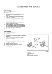
... pin 2. Remove the axle nut. Axle Removable wheel - Grease wheel bearings. Install hairpin cotter pin into the axle when removed to let the aerator rest on the wheel bushing. AR25 only 2 8058-025 23 Remove the hairpin cotter pin. 5. Install a new wheel with grease fitting facing out, with seals carefully in place on the tines. 3. MAINTENANCE AND SERVICE Rear Wheels Removal and Replacement Model AR19 1. Turn the rear wheel depth/stability control knob to adjust the rear wheels for...
... pin 2. Remove the axle nut. Axle Removable wheel - Grease wheel bearings. Install hairpin cotter pin into the axle when removed to let the aerator rest on the wheel bushing. AR25 only 2 8058-025 23 Remove the hairpin cotter pin. 5. Install a new wheel with grease fitting facing out, with seals carefully in place on the tines. 3. MAINTENANCE AND SERVICE Rear Wheels Removal and Replacement Model AR19 1. Turn the rear wheel depth/stability control knob to adjust the rear wheels for...
Operation Manual
Page 24
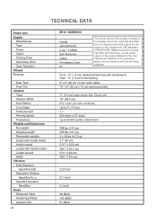
... Guaranteed Value Operator Ear 24 AR19 / 968982102 Honda GX120K1HX2 4 hp* / 2.98kW Belt Tensioner V-Belt Permalube Chain 6:1 *The power rating of the engine indicated is the average net power output (at specified rpm) of a typical production engine for the engine installed in the final machine will depend on the operating speed, environmental conditions and other variables. Actual power output for the engine model measured...
... Guaranteed Value Operator Ear 24 AR19 / 968982102 Honda GX120K1HX2 4 hp* / 2.98kW Belt Tensioner V-Belt Permalube Chain 6:1 *The power rating of the engine indicated is the average net power output (at specified rpm) of a typical production engine for the engine installed in the final machine will depend on the operating speed, environmental conditions and other variables. Actual power output for the engine model measured...


