Owner's Manual
Page 5
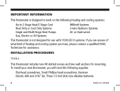
... screws and two wall anchors for mounting. IMPORTANT INFORMATION This thermostat is designed to work on the following heating and cooling systems: Up to 2 Stage Heat/2 Stage Cool Heat Only or Cool Only Systems Single and Multi-Stage Heat Pumps Gas, Electric or Oil Systems Millivolt Systems 2-wire Hydronic Systems AC or Hard-wired This thermostat is not...
... screws and two wall anchors for mounting. IMPORTANT INFORMATION This thermostat is designed to work on the following heating and cooling systems: Up to 2 Stage Heat/2 Stage Cool Heat Only or Cool Only Systems Single and Multi-Stage Heat Pumps Gas, Electric or Oil Systems Millivolt Systems 2-wire Hydronic Systems AC or Hard-wired This thermostat is not...
Owner's Manual
Page 12
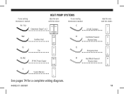
if your existing thermostat is marked: HEAT PUMP SYSTEMS label the wire with this sticker: if your existing thermostat is marked: label the wire with this sticker: Y1 / Y2 Compressor Stage 1 or 2 Y1 Y2 Y2 Y1 C 24 VAC Common C C O W2 Auxilliary Heat W2 W2 O Cool Mode Powered Reverse Valve O G Fan G G E Emergency Heat E E R/RC R / RC 24 VAC Power Supply R/RC B B Heat Mode Powered Reverse Valve B L L System Monitor L See pages 74 for a complete wiring diagram. 44002-01 r051807 11
if your existing thermostat is marked: HEAT PUMP SYSTEMS label the wire with this sticker: if your existing thermostat is marked: label the wire with this sticker: Y1 / Y2 Compressor Stage 1 or 2 Y1 Y2 Y2 Y1 C 24 VAC Common C C O W2 Auxilliary Heat W2 W2 O Cool Mode Powered Reverse Valve O G Fan G G E Emergency Heat E E R/RC R / RC 24 VAC Power Supply R/RC B B Heat Mode Powered Reverse Valve B L L System Monitor L See pages 74 for a complete wiring diagram. 44002-01 r051807 11
Owner's Manual
Page 28
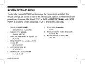
... are shown in bold in the following list. STAGE TWO SPAN (not available on page 26): 2F (1F, 2F, 3F) 4. RESIDUAL COOLING TIMER: 30 seconds (0, 30, 60, 90) 9. SYSTEM: CONVENTIONAL (CONVENTIONAL, HEAT PUMP) 2. STAGE ONE SPAN (defined on 1H/1C models): 2F (2F, 3F, 4F, 5F, 6F) 5. See pages 28-29 to change...TYPE is installed. FURNACE TYPE: GAS/OIL (GAS/OIL, ELECTRIC) 3. SYSTEM SETTINGS MENU The installer can set SYSTEM functions once the thermostat is CONVENTIONAL with (HEAT PUMP) as a second option. The default settings are listed inside the parentheses.
... are shown in bold in the following list. STAGE TWO SPAN (not available on page 26): 2F (1F, 2F, 3F) 4. RESIDUAL COOLING TIMER: 30 seconds (0, 30, 60, 90) 9. SYSTEM: CONVENTIONAL (CONVENTIONAL, HEAT PUMP) 2. STAGE ONE SPAN (defined on 1H/1C models): 2F (2F, 3F, 4F, 5F, 6F) 5. See pages 28-29 to change...TYPE is installed. FURNACE TYPE: GAS/OIL (GAS/OIL, ELECTRIC) 3. SYSTEM SETTINGS MENU The installer can set SYSTEM functions once the thermostat is CONVENTIONAL with (HEAT PUMP) as a second option. The default settings are listed inside the parentheses.
Owner's Manual
Page 38
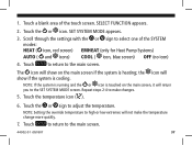
...will not make changes. 5. NOTE: If the system is running and the or icon is heating; Touch to return to the SET SYSTEM MODE screen. Touch the or icon. the icon will show if the system is cooling. SET SYSTEM MODE appears. 3. NOTE: Setting the override temperature to make the temperature change...the temperature icon ( ). 6. Scroll through the settings with the or sign to select one of the touch screen. Touch a blank area of the SYSTEM modes: HEAT ( icon, red screen) EMHEAT (only for Heat Pump Systems) AUTO ( and icons) COOL ( icon, blue screen) OFF (no icon) 4.
...will not make changes. 5. NOTE: If the system is running and the or icon is heating; Touch to return to the SET SYSTEM MODE screen. Touch the or icon. the icon will show if the system is cooling. SET SYSTEM MODE appears. 3. NOTE: Setting the override temperature to make the temperature change...the temperature icon ( ). 6. Scroll through the settings with the or sign to select one of the touch screen. Touch a blank area of the SYSTEM modes: HEAT ( icon, red screen) EMHEAT (only for Heat Pump Systems) AUTO ( and icons) COOL ( icon, blue screen) OFF (no icon) 4.

Owner's Manual
Page 75
Not all terminals need to be connected. • Add jumper between W2 and E terminals on the heat pump system requirement. RC/R C Y1 Heat Pump Systems Optional Jumper Y2 W2 E O B G L 24VAC Supply Compressor Compressor Auxiliary Emergency Reversing Valve Reversing Valve Fan System Stage 1 Stage 2 Heat Heat Cool Heat Control Monitor 24VAC Common (if available) Number of wires connected depends on systems without an E wire. 74 44002-01 r051807
Not all terminals need to be connected. • Add jumper between W2 and E terminals on the heat pump system requirement. RC/R C Y1 Heat Pump Systems Optional Jumper Y2 W2 E O B G L 24VAC Supply Compressor Compressor Auxiliary Emergency Reversing Valve Reversing Valve Fan System Stage 1 Stage 2 Heat Heat Cool Heat Control Monitor 24VAC Common (if available) Number of wires connected depends on systems without an E wire. 74 44002-01 r051807


