Owner's Manual
Page 1
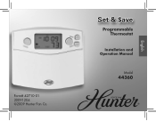
Form# 42710-01 20091204 ©2009 Hunter Fan Co. Set & $ave Programmable Thermostat Installation and Operation Manual Model 44360 English
Form# 42710-01 20091204 ©2009 Hunter Fan Co. Set & $ave Programmable Thermostat Installation and Operation Manual Model 44360 English

Owner's Manual
Page 3
Table of Contents Important Information 5 Tools...6 Uninstalling the Existing Unit 7 Installing the Thermostat 12 Installing the Wall Plate 12 Connecting the Wires 16 Attaching the Thermostat 18 Settings 22 Methods of Operation 26 Manual Operation / Override 28 Default Programs 32 Creating Custom Progams 34 Icons and Features 38 Important Features 52 Troubleshooting 53 3
Table of Contents Important Information 5 Tools...6 Uninstalling the Existing Unit 7 Installing the Thermostat 12 Installing the Wall Plate 12 Connecting the Wires 16 Attaching the Thermostat 18 Settings 22 Methods of Operation 26 Manual Operation / Override 28 Default Programs 32 Creating Custom Progams 34 Icons and Features 38 Important Features 52 Troubleshooting 53 3
Owner's Manual
Page 4
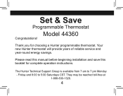
Set & Save Programmable Thermostat Model 44360 Congratulations! The Hunter Technical Support Group is available from 7 am to 5:00 Saturdays CST. Friday and 8:00 to 7 pm Monday - They may be reached toll-free at 1-888-830-1326. 4 Please read this manual before beginning installation and save this booklet for choosing a Hunter programmable thermostat. Thank you for complete operation instructions. Your new Hunter thermostat will provide years of reliable service and year-round energy savings.
Set & Save Programmable Thermostat Model 44360 Congratulations! The Hunter Technical Support Group is available from 7 am to 5:00 Saturdays CST. Friday and 8:00 to 7 pm Monday - They may be reached toll-free at 1-888-830-1326. 4 Please read this manual before beginning installation and save this booklet for choosing a Hunter programmable thermostat. Thank you for complete operation instructions. Your new Hunter thermostat will provide years of reliable service and year-round energy savings.
Owner's Manual
Page 6
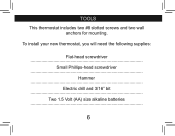
Tools This thermostat includes two #8 slotted screws and two wall anchors for mounting. To install your new thermostat, you will need the following supplies: Flat-head screwdriver Small Phillips-head screwdriver Hammer Electric drill and 3/16" bit Two 1.5 Volt (AA) size alkaline batteries 6
Tools This thermostat includes two #8 slotted screws and two wall anchors for mounting. To install your new thermostat, you will need the following supplies: Flat-head screwdriver Small Phillips-head screwdriver Hammer Electric drill and 3/16" bit Two 1.5 Volt (AA) size alkaline batteries 6
Owner's Manual
Page 13
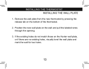
If the existing holes do not match those on the bottom of the thermostat. 2. installing the thermostat INSTALLING THE WALL PLATE 1. Remove the wall plate from the new thermostat by pressing the release tab on the Hunter wall plate, or if there are no existing holes, visually level the wall plate and mark the wall for two holes. 13 Position the new wall plate on the wall and pull the labeled wires through the opening. 3.
If the existing holes do not match those on the bottom of the thermostat. 2. installing the thermostat INSTALLING THE WALL PLATE 1. Remove the wall plate from the new thermostat by pressing the release tab on the Hunter wall plate, or if there are no existing holes, visually level the wall plate and mark the wall for two holes. 13 Position the new wall plate on the wall and pull the labeled wires through the opening. 3.
Owner's Manual
Page 15
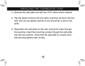
Reposition the wall plate on the wall, pulling the wires through the wall plate and into the holes until they are flush with the wall. (Do not use plastic anchors if you encounter a stud in the wall.) 6. Insert the mounting screws through the opening. Remove the wall plate and drill two 3/16" holes where marked. 5. Verify that the wall plate is visually level and securely tighten both screws. 15 Tap the plastic anchors into the anchors. installing the thermostat, cont. 4.
Reposition the wall plate on the wall, pulling the wires through the wall plate and into the holes until they are flush with the wall. (Do not use plastic anchors if you encounter a stud in the wall.) 6. Insert the mounting screws through the opening. Remove the wall plate and drill two 3/16" holes where marked. 5. Verify that the wall plate is visually level and securely tighten both screws. 15 Tap the plastic anchors into the anchors. installing the thermostat, cont. 4.

Owner's Manual
Page 17
... provide both an RH and RC wire, leave the jumper in electrical tape and carefully pushed back into the wall to the terminals as shown. installing the thermostat, cont. Loosen, but do not have both an RH and RC wire, remove this jumper. CONNECTING THE WIRES Jumper G RC RH Y W 1. If you...
... provide both an RH and RC wire, leave the jumper in electrical tape and carefully pushed back into the wall to the terminals as shown. installing the thermostat, cont. Loosen, but do not have both an RH and RC wire, remove this jumper. CONNECTING THE WIRES Jumper G RC RH Y W 1. If you...
Owner's Manual
Page 19
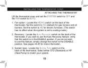
...) or HP (Heat Pump) to the DISABLE position. Set the switch to cooling mode.) 2. Locate the Auto Recovery switch on the back of the thermostat. installing the thermostat, cont. Locate the System Type switch on the back of the thermostat. ATTACHING THE THERMOSTAT Lift the thermostat cover and set to HE...
...) or HP (Heat Pump) to the DISABLE position. Set the switch to cooling mode.) 2. Locate the Auto Recovery switch on the back of the thermostat. installing the thermostat, cont. Locate the System Type switch on the back of the thermostat. ATTACHING THE THERMOSTAT Lift the thermostat cover and set to HE...
Owner's Manual
Page 21
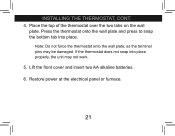
Press the thermostat onto the wall plate and press to snap the bottom tab into place properly, the unit may be damaged. installing the thermostat, cont. 4. Lift the front cover and insert two AA alkaline batteries. 6. Place the top of the thermostat over the two tabs on the wall plate. Note: Do not force the thermostat onto the wall plate, as the terminal pins may not work. 5. If the thermostat does not snap into place. Restore power at the electrical panel or furnace. 21
Press the thermostat onto the wall plate and press to snap the bottom tab into place properly, the unit may be damaged. installing the thermostat, cont. 4. Lift the front cover and insert two AA alkaline batteries. 6. Place the top of the thermostat over the two tabs on the wall plate. Note: Do not force the thermostat onto the wall plate, as the terminal pins may not work. 5. If the thermostat does not snap into place. Restore power at the electrical panel or furnace. 21
Owner's Manual
Page 47
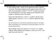
... C) above and below the set temperature.) The span setting can be adjusted if your cycle time by allowing the system to 2. 47 When batteries are installed, or the unit is cycling too fast or too slowly. Down will decrease your system is RESET, the span cycle will increase your cycle time...
... C) above and below the set temperature.) The span setting can be adjusted if your cycle time by allowing the system to 2. 47 When batteries are installed, or the unit is cycling too fast or too slowly. Down will decrease your system is RESET, the span cycle will increase your cycle time...
Owner's Manual
Page 49
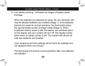
ICONS AND FEATURES, cont. 6. When the batteries are detected as weak, the icon will flash until new batteries are installed. (Your programs and time settings will be blank when no battery power is left . If the batteries become too weak for normal operation, the ... (Stage 2). The display will be lost if the batteries are not replaced within one minute.) The thermostat will resume normal operation after new batteries are installed (Stage 1). When insufficient battery power is left , the battery icon will flash alone on the display and your system will remain off . The system ...
ICONS AND FEATURES, cont. 6. When the batteries are detected as weak, the icon will flash until new batteries are installed. (Your programs and time settings will be blank when no battery power is left . If the batteries become too weak for normal operation, the ... (Stage 2). The display will be lost if the batteries are not replaced within one minute.) The thermostat will resume normal operation after new batteries are installed (Stage 1). When insufficient battery power is left , the battery icon will flash alone on the display and your system will remain off . The system ...
Owner's Manual
Page 56
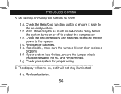
... set to the system. 5 d. Check your system has 4 wires, ensure the jumper wire is closed properly. 5 f. If applicable, make sure the furnace blower door is installed between the RC and RH terminals. 5 g. troubleshooting 5.
... set to the system. 5 d. Check your system has 4 wires, ensure the jumper wire is closed properly. 5 f. If applicable, make sure the furnace blower door is installed between the RC and RH terminals. 5 g. troubleshooting 5.
Owner's Manual
Page 3
Table of Contents Important Information 5 Tools...6 Uninstalling the Existing Unit 7 Installing the Thermostat 12 Installing the Wall Plate 12 Connecting the Wires 16 Attaching the Thermostat 18 Settings 22 Methods of Operation 26 Manual Operation / Override 28 Default Programs 32 Creating Custom Progams 34 Icons and Features 38 Important Features 52 Troubleshooting 53 3
Table of Contents Important Information 5 Tools...6 Uninstalling the Existing Unit 7 Installing the Thermostat 12 Installing the Wall Plate 12 Connecting the Wires 16 Attaching the Thermostat 18 Settings 22 Methods of Operation 26 Manual Operation / Override 28 Default Programs 32 Creating Custom Progams 34 Icons and Features 38 Important Features 52 Troubleshooting 53 3


