
Owner's Manual
Page 3
Table of Contents Important Information 5 Tools...6 Uninstalling the Existing Unit 7 Installing the Thermostat 12 Installing the Wall Plate 12 Connecting the Wires 16 Attaching the Thermostat 18 Settings 22 Methods of Operation 26 Manual Operation / Override 28 Default Programs 32 Creating Custom Progams 34 Icons and Features 38 Important Features 52 Troubleshooting 53 3
Table of Contents Important Information 5 Tools...6 Uninstalling the Existing Unit 7 Installing the Thermostat 12 Installing the Wall Plate 12 Connecting the Wires 16 Attaching the Thermostat 18 Settings 22 Methods of Operation 26 Manual Operation / Override 28 Default Programs 32 Creating Custom Progams 34 Icons and Features 38 Important Features 52 Troubleshooting 53 3
Owner's Manual
Page 7
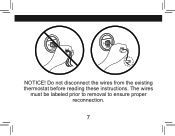
RC Y G W RC Y G W w NOTICE! The wires must be labeled prior to removal to ensure proper reconnection. 7 Do not disconnect the wires from the existing thermostat before reading these instructions.
RC Y G W RC Y G W w NOTICE! The wires must be labeled prior to removal to ensure proper reconnection. 7 Do not disconnect the wires from the existing thermostat before reading these instructions.
Owner's Manual
Page 9
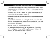
... not visible, they may be removed or disengaged. Some models may have doors that must be connected to expose the wires and mounting screws.) 9 Turn the system power OFF from the wall. (Some thermostats may have multiple covers, screws or other locking devices that open to ... the power to the HVAC system OFF at the main power panel or at the furnace. (Failure to turn off the power to access the wires from the existing thermostat. See page 8 for common examples.) 3.
... not visible, they may be removed or disengaged. Some models may have doors that must be connected to expose the wires and mounting screws.) 9 Turn the system power OFF from the wall. (Some thermostats may have multiple covers, screws or other locking devices that open to ... the power to the HVAC system OFF at the main power panel or at the furnace. (Failure to turn off the power to access the wires from the existing thermostat. See page 8 for common examples.) 3.
Owner's Manual
Page 10
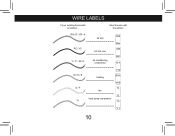
label the wire with this sticker: RH / R / VR / 4 24 Volt RH RC / VC 24 Volt cool RC Y / C* / M / O air conditioning compressor W / H / B G / F Y1 heating Y/0 W/B fan G heat pump compressor Y1 10 Y1 G W/B Y/0 RC RH wire labels if your existing thermostat is marked...
label the wire with this sticker: RH / R / VR / 4 24 Volt RH RC / VC 24 Volt cool RC Y / C* / M / O air conditioning compressor W / H / B G / F Y1 heating Y/0 W/B fan G heat pump compressor Y1 10 Y1 G W/B Y/0 RC RH wire labels if your existing thermostat is marked...

Owner's Manual
Page 11
... the existing terminal designation for non-battery powered thermostats. 5. You may be a Common wire and should be capped with standards, so wire color should be used only for proper identification. *If wires marked Y & C are labeled, disconnect each wire according to the Wire Labels chart. (If the terminals are not labeled, contact a qualified HVAC technician.) W RC...
... the existing terminal designation for non-battery powered thermostats. 5. You may be a Common wire and should be capped with standards, so wire color should be used only for proper identification. *If wires marked Y & C are labeled, disconnect each wire according to the Wire Labels chart. (If the terminals are not labeled, contact a qualified HVAC technician.) W RC...
Owner's Manual
Page 13
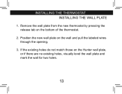
Remove the wall plate from the new thermostat by pressing the release tab on the wall and pull the labeled wires through the opening. 3. Position the new wall plate on the bottom of the thermostat. 2. If the existing holes do not match those on the Hunter wall plate, or if there are no existing holes, visually level the wall plate and mark the wall for two holes. 13 installing the thermostat INSTALLING THE WALL PLATE 1.
Remove the wall plate from the new thermostat by pressing the release tab on the wall and pull the labeled wires through the opening. 3. Position the new wall plate on the bottom of the thermostat. 2. If the existing holes do not match those on the Hunter wall plate, or if there are no existing holes, visually level the wall plate and mark the wall for two holes. 13 installing the thermostat INSTALLING THE WALL PLATE 1.
Owner's Manual
Page 15
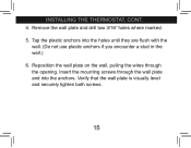
Remove the wall plate and drill two 3/16" holes where marked. 5. Reposition the wall plate on the wall, pulling the wires through the wall plate and into the holes until they are flush with the wall. (Do not use plastic anchors if you encounter a stud in the wall.) 6. Verify that the wall plate is visually level and securely tighten both screws. 15 Tap the plastic anchors into the anchors. Insert the mounting screws through the opening. installing the thermostat, cont. 4.
Remove the wall plate and drill two 3/16" holes where marked. 5. Reposition the wall plate on the wall, pulling the wires through the wall plate and into the holes until they are flush with the wall. (Do not use plastic anchors if you encounter a stud in the wall.) 6. Verify that the wall plate is visually level and securely tighten both screws. 15 Tap the plastic anchors into the anchors. Insert the mounting screws through the opening. installing the thermostat, cont. 4.

Owner's Manual
Page 17
...do not have both an RH and RC wire, remove this jumper. Wires should be inserted behind the black terminal shields. Note: A jumper wire has been provided, connecting the RC and RH terminals for systems that do not provide both an RH and RC wire, leave the jumper in electrical tape and... carefully pushed back into the wall to the terminals as shown. Match and connect the wires from the wall to prevent interference. 17 Push any extra wires should be individually wrapped in place. 2. Tighten each screw after the connection has been made. (The ends ...
...do not have both an RH and RC wire, remove this jumper. Wires should be inserted behind the black terminal shields. Note: A jumper wire has been provided, connecting the RC and RH terminals for systems that do not provide both an RH and RC wire, leave the jumper in electrical tape and... carefully pushed back into the wall to the terminals as shown. Match and connect the wires from the wall to prevent interference. 17 Push any extra wires should be individually wrapped in place. 2. Tighten each screw after the connection has been made. (The ends ...
Owner's Manual
Page 56
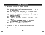
Replace the batteries. 5 e. Check your system has 4 wires, ensure the jumper wire is power to the desired position. 5 b. Replace batteries. 56 troubleshooting 5. There may be as much as a 4-minute delay before the system turns on or off ... between the RC and RH terminals. 5 g. Wait. If applicable, make sure the furnace blower door is set to the system. 5 d. If your system for proper wiring 6. Check the Heat/Cool function switch to protect the compressor. 5 c. The display will come on, but it is closed properly. 5 f. My heating or cooling will...
Replace the batteries. 5 e. Check your system has 4 wires, ensure the jumper wire is power to the desired position. 5 b. Replace batteries. 56 troubleshooting 5. There may be as much as a 4-minute delay before the system turns on or off ... between the RC and RH terminals. 5 g. Wait. If applicable, make sure the furnace blower door is set to the system. 5 d. If your system for proper wiring 6. Check the Heat/Cool function switch to protect the compressor. 5 c. The display will come on, but it is closed properly. 5 f. My heating or cooling will...
Owner's Manual
Page 57
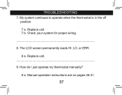
Check your system for proper wiring. 8. Replace unit 9. Manual operation instructions are on pages 28-31. 57 Replace unit. 7 b. My system continues to operate when the thermostat is in the off position. 7 a. The LCD screen permanently reads HI, LO, or ERR. 8 a. troubleshooting 7. How do I just operate my thermostat manually? 9 a.
Check your system for proper wiring. 8. Replace unit 9. Manual operation instructions are on pages 28-31. 57 Replace unit. 7 b. My system continues to operate when the thermostat is in the off position. 7 a. The LCD screen permanently reads HI, LO, or ERR. 8 a. troubleshooting 7. How do I just operate my thermostat manually? 9 a.
Owner's Manual
Page 3
Table of Contents Important Information 5 Tools...6 Uninstalling the Existing Unit 7 Installing the Thermostat 12 Installing the Wall Plate 12 Connecting the Wires 16 Attaching the Thermostat 18 Settings 22 Methods of Operation 26 Manual Operation / Override 28 Default Programs 32 Creating Custom Progams 34 Icons and Features 38 Important Features 52 Troubleshooting 53 3
Table of Contents Important Information 5 Tools...6 Uninstalling the Existing Unit 7 Installing the Thermostat 12 Installing the Wall Plate 12 Connecting the Wires 16 Attaching the Thermostat 18 Settings 22 Methods of Operation 26 Manual Operation / Override 28 Default Programs 32 Creating Custom Progams 34 Icons and Features 38 Important Features 52 Troubleshooting 53 3


