Owner's Manual
Page 1
Form# 42710-01 20091204 ©2009 Hunter Fan Co. Set & $ave Programmable Thermostat Installation and Operation Manual Model 44360 English
Form# 42710-01 20091204 ©2009 Hunter Fan Co. Set & $ave Programmable Thermostat Installation and Operation Manual Model 44360 English

Owner's Manual
Page 3
Table of Contents Important Information 5 Tools...6 Uninstalling the Existing Unit 7 Installing the Thermostat 12 Installing the Wall Plate 12 Connecting the Wires 16 Attaching the Thermostat 18 Settings 22 Methods of Operation 26 Manual Operation / Override 28 Default Programs 32 Creating Custom Progams 34 Icons and Features 38 Important Features 52 Troubleshooting 53 3
Table of Contents Important Information 5 Tools...6 Uninstalling the Existing Unit 7 Installing the Thermostat 12 Installing the Wall Plate 12 Connecting the Wires 16 Attaching the Thermostat 18 Settings 22 Methods of Operation 26 Manual Operation / Override 28 Default Programs 32 Creating Custom Progams 34 Icons and Features 38 Important Features 52 Troubleshooting 53 3
Owner's Manual
Page 4
Thank you for complete operation instructions. Please read this manual before beginning installation and save this booklet for choosing a Hunter programmable thermostat. The Hunter Technical Support Group is available from 7 am to 5:00 Saturdays CST. Friday and 8:00 to 7 pm Monday - Your new Hunter thermostat will provide years of reliable service and year-round energy savings. Set & Save Programmable Thermostat Model 44360 Congratulations! They may be reached toll-free at 1-888-830-1326. 4
Thank you for complete operation instructions. Please read this manual before beginning installation and save this booklet for choosing a Hunter programmable thermostat. The Hunter Technical Support Group is available from 7 am to 5:00 Saturdays CST. Friday and 8:00 to 7 pm Monday - Your new Hunter thermostat will provide years of reliable service and year-round energy savings. Set & Save Programmable Thermostat Model 44360 Congratulations! They may be reached toll-free at 1-888-830-1326. 4
Owner's Manual
Page 5
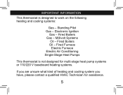
important information This thermostat is not designed for multi-stage heat pump systems or 110/220 V baseboard heating systems. If you are unsure what kind of heating and cooling system you have, please contact a qualified HVAC Technician for assistance. 5 Millivolt Systems Oil - Fired Boilers Gas - Fired Furnace Electric Furnace Electric Air Conditioning Single-Stage Heat Pumps This thermostat is designed to work on the following heating and cooling systems: Gas - Fired Boilers Oil - Standing Pilot Gas - Electronic Ignition Gas -
important information This thermostat is not designed for multi-stage heat pump systems or 110/220 V baseboard heating systems. If you are unsure what kind of heating and cooling system you have, please contact a qualified HVAC Technician for assistance. 5 Millivolt Systems Oil - Fired Boilers Gas - Fired Furnace Electric Furnace Electric Air Conditioning Single-Stage Heat Pumps This thermostat is designed to work on the following heating and cooling systems: Gas - Fired Boilers Oil - Standing Pilot Gas - Electronic Ignition Gas -
Owner's Manual
Page 6
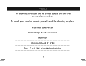
Tools This thermostat includes two #8 slotted screws and two wall anchors for mounting. To install your new thermostat, you will need the following supplies: Flat-head screwdriver Small Phillips-head screwdriver Hammer Electric drill and 3/16" bit Two 1.5 Volt (AA) size alkaline batteries 6
Tools This thermostat includes two #8 slotted screws and two wall anchors for mounting. To install your new thermostat, you will need the following supplies: Flat-head screwdriver Small Phillips-head screwdriver Hammer Electric drill and 3/16" bit Two 1.5 Volt (AA) size alkaline batteries 6
Owner's Manual
Page 7
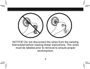
RC Y G W RC Y G W w NOTICE! Do not disconnect the wires from the existing thermostat before reading these instructions. The wires must be labeled prior to removal to ensure proper reconnection. 7
RC Y G W RC Y G W w NOTICE! Do not disconnect the wires from the existing thermostat before reading these instructions. The wires must be labeled prior to removal to ensure proper reconnection. 7
Owner's Manual
Page 9
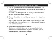
..., screws or other locking devices that open to access the wires from the existing thermostat. Remove the existing thermostat cover to expose the wires and mounting screws.) 9 Turn the system power OFF from the wall. (Some thermostats may be removed or disengaged. See page 8 for common examples.) 3. Locate, ...but do not disconnect the wires. (If wires are not visible, they may have doors that must be connected to the existing thermostat before removal could damage your system.) 2. Turn the power to the HVAC system OFF at the main power panel or at the furnace. (...
..., screws or other locking devices that open to access the wires from the existing thermostat. Remove the existing thermostat cover to expose the wires and mounting screws.) 9 Turn the system power OFF from the wall. (Some thermostats may be removed or disengaged. See page 8 for common examples.) 3. Locate, ...but do not disconnect the wires. (If wires are not visible, they may have doors that must be connected to the existing thermostat before removal could damage your system.) 2. Turn the power to the HVAC system OFF at the main power panel or at the furnace. (...
Owner's Manual
Page 10
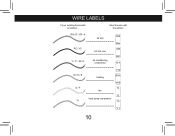
Y1 G W/B Y/0 RC RH wire labels if your existing thermostat is marked... label the wire with this sticker: RH / R / VR / 4 24 Volt RH RC / VC 24 Volt cool RC Y / C* / M / O air conditioning compressor W / H / B G / F Y1 heating Y/0 W/B fan G heat pump compressor Y1 10
Y1 G W/B Y/0 RC RH wire labels if your existing thermostat is marked... label the wire with this sticker: RH / R / VR / 4 24 Volt RH RC / VC 24 Volt cool RC Y / C* / M / O air conditioning compressor W / H / B G / F Y1 heating Y/0 W/B fan G heat pump compressor Y1 10

Owner's Manual
Page 11
.... If you disconnect them. After all wires are both present, C may want to secure the wires to the existing terminal designation for non-battery powered thermostats. 5. uninstalling the existing unit, cont. 4. Refer to the wall as you have a wire marked C, do not always comply with an approved electrical connector, such as...
.... If you disconnect them. After all wires are both present, C may want to secure the wires to the existing terminal designation for non-battery powered thermostats. 5. uninstalling the existing unit, cont. 4. Refer to the wall as you have a wire marked C, do not always comply with an approved electrical connector, such as...
Owner's Manual
Page 13
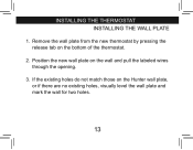
If the existing holes do not match those on the wall and pull the labeled wires through the opening. 3. Position the new wall plate on the Hunter wall plate, or if there are no existing holes, visually level the wall plate and mark the wall for two holes. 13 Remove the wall plate from the new thermostat by pressing the release tab on the bottom of the thermostat. 2. installing the thermostat INSTALLING THE WALL PLATE 1.
If the existing holes do not match those on the wall and pull the labeled wires through the opening. 3. Position the new wall plate on the Hunter wall plate, or if there are no existing holes, visually level the wall plate and mark the wall for two holes. 13 Remove the wall plate from the new thermostat by pressing the release tab on the bottom of the thermostat. 2. installing the thermostat INSTALLING THE WALL PLATE 1.
Owner's Manual
Page 15
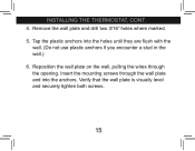
Tap the plastic anchors into the anchors. Verify that the wall plate is visually level and securely tighten both screws. 15 Insert the mounting screws through the opening. Reposition the wall plate on the wall, pulling the wires through the wall plate and into the holes until they are flush with the wall. (Do not use plastic anchors if you encounter a stud in the wall.) 6. Remove the wall plate and drill two 3/16" holes where marked. 5. installing the thermostat, cont. 4.
Tap the plastic anchors into the anchors. Verify that the wall plate is visually level and securely tighten both screws. 15 Insert the mounting screws through the opening. Reposition the wall plate on the wall, pulling the wires through the wall plate and into the holes until they are flush with the wall. (Do not use plastic anchors if you encounter a stud in the wall.) 6. Remove the wall plate and drill two 3/16" holes where marked. 5. installing the thermostat, cont. 4.

Owner's Manual
Page 17
..., remove this jumper. Tighten each screw after the connection has been made. (The ends of any excess wire length back into the wall.) 3. installing the thermostat, cont. Note: A jumper wire has been provided, connecting the RC and RH terminals for systems that do not remove, the terminal screws.
..., remove this jumper. Tighten each screw after the connection has been made. (The ends of any excess wire length back into the wall.) 3. installing the thermostat, cont. Note: A jumper wire has been provided, connecting the RC and RH terminals for systems that do not remove, the terminal screws.
Owner's Manual
Page 18
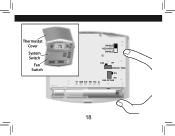
Thermostat Cover T AM 4 HEAT System Switch Fan Switch ENABLE RECOVERY DISABLE STD HP SYSTEM TYPE HG Y1 W/B Y/O RH RC G HE FAN OPTION 18
Thermostat Cover T AM 4 HEAT System Switch Fan Switch ENABLE RECOVERY DISABLE STD HP SYSTEM TYPE HG Y1 W/B Y/O RH RC G HE FAN OPTION 18
Owner's Manual
Page 19
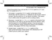
.... 19 Recovery - System type - Select either STD (Standard) or HP (Heat Pump) to HG (default) for gas furnace and oil burners. ATTACHING THE THERMOSTAT Lift the thermostat cover and set to the DISABLE position. See pages 44-45 for electric furnaces. (The switch has no effect when the system is set... switch is in the ENABLE position. If you wish to AUTO. 1. Locate the HE/HG switch on the back of the thermostat. Locate the System Type switch on the back of the thermostat. Set the switch to HE for more information. 3. Locate the Auto Recovery switch on the back of the...
.... 19 Recovery - System type - Select either STD (Standard) or HP (Heat Pump) to HG (default) for gas furnace and oil burners. ATTACHING THE THERMOSTAT Lift the thermostat cover and set to the DISABLE position. See pages 44-45 for electric furnaces. (The switch has no effect when the system is set... switch is in the ENABLE position. If you wish to AUTO. 1. Locate the HE/HG switch on the back of the thermostat. Locate the System Type switch on the back of the thermostat. Set the switch to HE for more information. 3. Locate the Auto Recovery switch on the back of the...
Owner's Manual
Page 21
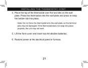
Place the top of the thermostat over the two tabs on the wall plate. If the thermostat does not snap into place. Lift the front cover and insert two AA alkaline batteries. 6. Restore power at the electrical panel or furnace. 21 Press the thermostat onto the wall plate and press to snap the bottom tab into place properly, the unit may be damaged. installing the thermostat, cont. 4. Note: Do not force the thermostat onto the wall plate, as the terminal pins may not work. 5.
Place the top of the thermostat over the two tabs on the wall plate. If the thermostat does not snap into place. Lift the front cover and insert two AA alkaline batteries. 6. Restore power at the electrical panel or furnace. 21 Press the thermostat onto the wall plate and press to snap the bottom tab into place properly, the unit may be damaged. installing the thermostat, cont. 4. Note: Do not force the thermostat onto the wall plate, as the terminal pins may not work. 5.
Owner's Manual
Page 23
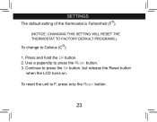
Continue to Celsius (Co): 1. settings The default setting of the thermostat is Fahrenheit (Fo). (NOTICE: CHANGING THIS SETTING WILL RESET THE THERMOSTAT TO FACTORY DEFAULT PROGRAMS.) To change to press the Up button, but release the Reset button when the LCD turns on. Use a paperclip to F, press only the Reset button. 23 Press and hold the Up button. 2. To reset the unit to press the Reset button. 3.
Continue to Celsius (Co): 1. settings The default setting of the thermostat is Fahrenheit (Fo). (NOTICE: CHANGING THIS SETTING WILL RESET THE THERMOSTAT TO FACTORY DEFAULT PROGRAMS.) To change to press the Up button, but release the Reset button when the LCD turns on. Use a paperclip to F, press only the Reset button. 23 Press and hold the Up button. 2. To reset the unit to press the Reset button. 3.
Owner's Manual
Page 25
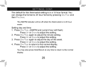
... the format to adjust the setting. 3. Press Up or Down to 24 hour format by pressing Day/Time and then Program. The default for this thermostat setting is in a 12 hour format. Press Day/Time again to adjust the setting. 2. Setting day and time: 1. Press Day/Time. (AM/PM and current... hour will be off when the thermostat is in 24 hour mode. You may also press Hold/Return at any time to return to the normal display. The AM/PM indicator will...
... the format to adjust the setting. 3. Press Up or Down to 24 hour format by pressing Day/Time and then Program. The default for this thermostat setting is in a 12 hour format. Press Day/Time again to adjust the setting. 2. Setting day and time: 1. Press Day/Time. (AM/PM and current... hour will be off when the thermostat is in 24 hour mode. You may also press Hold/Return at any time to return to the normal display. The AM/PM indicator will...

Owner's Manual
Page 27
To utilize the pre-programmed settings, see pages 28-35. methods of operation This thermostat gives you the ability to program up to 4 custom temperature settings per day or utilize pre-programmed settings. For manual operation / override instructions, see pages 36-37. To create custom programs, see pages 38-41. 27
To utilize the pre-programmed settings, see pages 28-35. methods of operation This thermostat gives you the ability to program up to 4 custom temperature settings per day or utilize pre-programmed settings. For manual operation / override instructions, see pages 36-37. To create custom programs, see pages 38-41. 27
Owner's Manual
Page 29
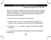
... button when the display flashes.) 2. Press the Up or Down buttons to only override the current program: 1. The system will revert back to operate their thermostats manually, adjusting settings as desired. MANUAL OPERATION / OVERRIDE Many people prefer to the program at the next scheduled program time. 29
... button when the display flashes.) 2. Press the Up or Down buttons to only override the current program: 1. The system will revert back to operate their thermostats manually, adjusting settings as desired. MANUAL OPERATION / OVERRIDE Many people prefer to the program at the next scheduled program time. 29
Owner's Manual
Page 31
Press and release Hold/Return to return to enter Manual Override mode. (Release the button when the display flashes.) 3. Press and hold Up or Down for one second to the normal display. 31 Press the Up or Down buttons to permanently override all settings and adjust the thermostat manually: 1. Press Hold/Return until the Hold icon appears. 2. PERMANENT OVERRIDE If you want to adjust the temperature setting as desired. 4. methods of operation 2.
Press and release Hold/Return to return to enter Manual Override mode. (Release the button when the display flashes.) 3. Press and hold Up or Down for one second to the normal display. 31 Press the Up or Down buttons to permanently override all settings and adjust the thermostat manually: 1. Press Hold/Return until the Hold icon appears. 2. PERMANENT OVERRIDE If you want to adjust the temperature setting as desired. 4. methods of operation 2.


