Owner's Manual
Page 5
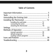
Table of Contents Important Information 5 Tools 6 Uninstalling the Existing Unit 7 Installing the Thermostat 12 installing the wall plate 12 connecting the wires 16 attaching the thermostat 18 Settings 22 Methods of Operation 26 manual operation 28 default programs 32 creating custom programs 34 Icons and Features 38 Troubleshooting 49 3
Table of Contents Important Information 5 Tools 6 Uninstalling the Existing Unit 7 Installing the Thermostat 12 installing the wall plate 12 connecting the wires 16 attaching the thermostat 18 Settings 22 Methods of Operation 26 manual operation 28 default programs 32 creating custom programs 34 Icons and Features 38 Troubleshooting 49 3
Owner's Manual
Page 9
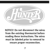
NOTICE! Do not disconnect the wires from the existing thermostat before reading these instructions. The wires must be labeled prior to removal to ensure proper reconnection. 7
NOTICE! Do not disconnect the wires from the existing thermostat before reading these instructions. The wires must be labeled prior to removal to ensure proper reconnection. 7
Owner's Manual
Page 11
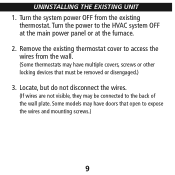
UNINSTALLING THE EXISTING UNIT 1. Locate, but do not disconnect the wires. (If wires are not visible, they may be removed or disengaged.) 3. Turn the power to expose the wires and mounting screws.) 9 Some models may have doors that must be connected to access the wires from the existing thermostat. Turn the system power OFF from the wall. (Some thermostats may have multiple covers, screws or other locking devices that open to the HVAC system OFF at the main power panel or at the furnace. 2. Remove the existing thermostat cover to the back of the wall plate.
UNINSTALLING THE EXISTING UNIT 1. Locate, but do not disconnect the wires. (If wires are not visible, they may be removed or disengaged.) 3. Turn the power to expose the wires and mounting screws.) 9 Some models may have doors that must be connected to access the wires from the existing thermostat. Turn the system power OFF from the wall. (Some thermostats may have multiple covers, screws or other locking devices that open to the HVAC system OFF at the main power panel or at the furnace. 2. Remove the existing thermostat cover to the back of the wall plate.
Owner's Manual
Page 12
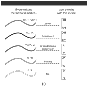
label the wire with this sticker: G W Y RC RH RH / R / VR / 4 24 Volt RH RC / VC 24 Volt cool RC Y / C* / M air conditioning compressor Y W / H heating W G / F fan G 10 if your existing thermostat is marked...
label the wire with this sticker: G W Y RC RH RH / R / VR / 4 24 Volt RH RC / VC 24 Volt cool RC Y / C* / M air conditioning compressor Y W / H heating W G / F fan G 10 if your existing thermostat is marked...
Owner's Manual
Page 13
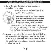
...during disconnection. If you disconnect them. You may be a Common wire and should be used only for proper identification. *If wires marked Y & C are not labeled, contact a qualified HVAC technician.) W RC Y G W Note: Wire colors do not connect it to the existing terminal designation for non-...battery powered thermostats. 5. Using the provided stickers, label each wire and remove the existing wall plate. 11 This wire is used . After all wires are labeled, disconnect each wire according to the chart. (If the terminals are both present, C may want...
...during disconnection. If you disconnect them. You may be a Common wire and should be used only for proper identification. *If wires marked Y & C are not labeled, contact a qualified HVAC technician.) W RC Y G W Note: Wire colors do not connect it to the existing terminal designation for non-...battery powered thermostats. 5. Using the provided stickers, label each wire and remove the existing wall plate. 11 This wire is used . After all wires are labeled, disconnect each wire according to the chart. (If the terminals are both present, C may want...
Owner's Manual
Page 15
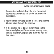
Position the new wall plate on the Hunter wall plate, or if there are no existing holes, visually level the wall plate and mark the wall for two holes. 13 If the existing holes do not match those on the wall and pull the labeled wires through the opening. 3. Remove the wall plate from the new thermostat by pressing the release tab on the bottom of the thermostat. 2. INSTALLING THE THERMOSTAT INSTALLING THE WALL PLATE 1.
Position the new wall plate on the Hunter wall plate, or if there are no existing holes, visually level the wall plate and mark the wall for two holes. 13 If the existing holes do not match those on the wall and pull the labeled wires through the opening. 3. Remove the wall plate from the new thermostat by pressing the release tab on the bottom of the thermostat. 2. INSTALLING THE THERMOSTAT INSTALLING THE WALL PLATE 1.
Owner's Manual
Page 17
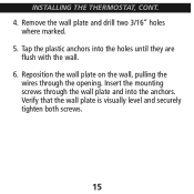
Tap the plastic anchors into the anchors. Remove the wall plate and drill two 3/16" holes where marked. 5. Verify that the wall plate is visually level and securely tighten both screws. 15 Insert the mounting screws through the opening. Reposition the wall plate on the wall, pulling the wires through the wall plate and into the holes until they are flush with the wall. 6. INSTALLING THE THERMOSTAT, CONT. 4.
Tap the plastic anchors into the anchors. Remove the wall plate and drill two 3/16" holes where marked. 5. Verify that the wall plate is visually level and securely tighten both screws. 15 Insert the mounting screws through the opening. Reposition the wall plate on the wall, pulling the wires through the wall plate and into the holes until they are flush with the wall. 6. INSTALLING THE THERMOSTAT, CONT. 4.
Owner's Manual
Page 19
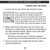
... been provided, connecting the RC and RH terminals for systems that do not provide both an RH and RC wire, leave the jumper in electrical tape and carefully pushed back into the wall to the terminals as shown. If you do not remove, the terminal ...screws. Loosen, but do not have both an RH and RC wire, remove this jumper. Match and connect the wires from the wall to prevent interference. 17 Wires should be inserted behind the black terminal shields. CONNECTING THE WIRES 1. Tighten each screw after the connection has been made. (The ends of any...
... been provided, connecting the RC and RH terminals for systems that do not provide both an RH and RC wire, leave the jumper in electrical tape and carefully pushed back into the wall to the terminals as shown. If you do not remove, the terminal ...screws. Loosen, but do not have both an RH and RC wire, remove this jumper. Match and connect the wires from the wall to prevent interference. 17 Wires should be inserted behind the black terminal shields. CONNECTING THE WIRES 1. Tighten each screw after the connection has been made. (The ends of any...
Owner's Manual
Page 52
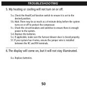
... be as much as a 4-minute delay before the system turns on , but it is installed between the RC and RH terminals. 6. If your system has 4 wires, ensure the jumper wire is set to ensure it will come on or off . 5 a. The display will not stay illuminated. 6 a.
... be as much as a 4-minute delay before the system turns on , but it is installed between the RC and RH terminals. 6. If your system has 4 wires, ensure the jumper wire is set to ensure it will come on or off . 5 a. The display will not stay illuminated. 6 a.
Owner's Manual
Page 1
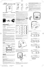
... If you follow the labeling procedures correctly, you require further assistance, call Hunter Technical Support at the furnace. ■ Remove existing thermostat cover and thermostat. RC ■ IMPORTANT! This wire provides Relay electricity to change the batteries and keep thermostat's clock and program ...Press the top of two AA 1.5V batteries. Tape up the wire and do not line up settings. Your new Hunter thermostat will prevent damage to the normal display from Hunter Air Purifiers CeilingFans Humidifiers IMPORTANT INFORMATION 1. AJ705/41433 #1/art 6/7/04 ...
... If you follow the labeling procedures correctly, you require further assistance, call Hunter Technical Support at the furnace. ■ Remove existing thermostat cover and thermostat. RC ■ IMPORTANT! This wire provides Relay electricity to change the batteries and keep thermostat's clock and program ...Press the top of two AA 1.5V batteries. Tape up the wire and do not line up settings. Your new Hunter thermostat will prevent damage to the normal display from Hunter Air Purifiers CeilingFans Humidifiers IMPORTANT INFORMATION 1. AJ705/41433 #1/art 6/7/04 ...

Owner's Manual
Page 2
...Check your circuit breakers and switches to ensure there is also a selector switch for both HEAT and COOL. If your system only uses 4-wires, be flashing. Then reprogram. 1. Replace unit. TH PM HOLD TEMP ■ You can be displayed on the front of the thermostat ...Fan will flash to your program settings, press PROGRAM repeatedly to cycle through 5 to provide a comfortable room temperature under most other problems, call Hunter Technical support at any other systems. "HE" position is independent of time: HOLD/RET ■ Press to change temperature mode. FAN ON...
...Check your circuit breakers and switches to ensure there is also a selector switch for both HEAT and COOL. If your system only uses 4-wires, be flashing. Then reprogram. 1. Replace unit. TH PM HOLD TEMP ■ You can be displayed on the front of the thermostat ...Fan will flash to your program settings, press PROGRAM repeatedly to cycle through 5 to provide a comfortable room temperature under most other problems, call Hunter Technical support at any other systems. "HE" position is independent of time: HOLD/RET ■ Press to change temperature mode. FAN ON...


