Owner's Manual
Page 1
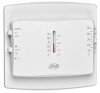
Electronic/Mechanical Thermostat installation and operation manual Model 40120 1 44018-01 04-01-2008
Electronic/Mechanical Thermostat installation and operation manual Model 40120 1 44018-01 04-01-2008
Owner's Manual
Page 3
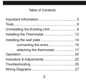
Table of Contents Important Information 5 Tools 6 Uninstalling the Existing Unit 9 Installing the Thermostat 12 Installing the wall plate 14 connecting the wires 15 attaching the thermostat 17 Operation 20 Indicators & Adjustments 22 Troubleshooting 25 Wiring Diagrams 27 3
Table of Contents Important Information 5 Tools 6 Uninstalling the Existing Unit 9 Installing the Thermostat 12 Installing the wall plate 14 connecting the wires 15 attaching the thermostat 17 Operation 20 Indicators & Adjustments 22 Troubleshooting 25 Wiring Diagrams 27 3
Owner's Manual
Page 4
Electronic/Mechanical Thermostat Model 40120 Congratulations! Your new Hunter thermostat will provide years of reliable service and year-round energy savings. Please read this manual before beginning installation and save this booklet for choosing a Hunter thermostat. Thank you for complete operation instructions. 4
Electronic/Mechanical Thermostat Model 40120 Congratulations! Your new Hunter thermostat will provide years of reliable service and year-round energy savings. Please read this manual before beginning installation and save this booklet for choosing a Hunter thermostat. Thank you for complete operation instructions. 4
Owner's Manual
Page 5
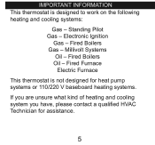
Fired Boilers Oil - Fired Boilers Gas - important information This thermostat is not designed for heat pump systems or 110/220 V baseboard heating systems. If you are unsure what kind of heating and cooling system you have, please contact a qualified HVAC Technician for assistance. 5 Standing Pilot Gas - Fired Furnace Electric Furnace This thermostat is designed to work on the following heating and cooling systems: Gas - Millivolt Systems Oil - Electronic Ignition Gas -
Fired Boilers Oil - Fired Boilers Gas - important information This thermostat is not designed for heat pump systems or 110/220 V baseboard heating systems. If you are unsure what kind of heating and cooling system you have, please contact a qualified HVAC Technician for assistance. 5 Standing Pilot Gas - Fired Furnace Electric Furnace This thermostat is designed to work on the following heating and cooling systems: Gas - Millivolt Systems Oil - Electronic Ignition Gas -
Owner's Manual
Page 6
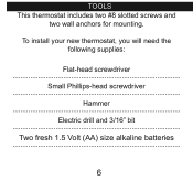
Tools This thermostat includes two #8 slotted screws and two wall anchors for mounting. To install your new thermostat, you will need the following supplies: Flat-head screwdriver Small Phillips-head screwdriver Hammer Electric drill and 3/16" bit Two fresh 1.5 Volt (AA) size alkaline batteries 6
Tools This thermostat includes two #8 slotted screws and two wall anchors for mounting. To install your new thermostat, you will need the following supplies: Flat-head screwdriver Small Phillips-head screwdriver Hammer Electric drill and 3/16" bit Two fresh 1.5 Volt (AA) size alkaline batteries 6
Owner's Manual
Page 7
The wires must be labeled prior to removal to ensure proper reconnection. 7 Do not disconnect the wires from the existing thermostat before reading these instructions. NOTICE!
The wires must be labeled prior to removal to ensure proper reconnection. 7 Do not disconnect the wires from the existing thermostat before reading these instructions. NOTICE!
Owner's Manual
Page 9
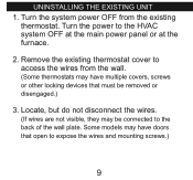
Remove the existing thermostat cover to expose the wires and mounting screws.) 9 Locate, but do not disconnect the wires. (If wires are not visible, they may be removed or disengaged.) 3. uninstalling the existing unit 1. Some models may have doors that must be connected to the HVAC system OFF at the main power panel or at the furnace. 2. Turn the system power OFF from the wall. (Some thermostats may have multiple covers, screws or other locking devices that open to access the wires from the existing thermostat. Turn the power to the back of the wall plate.
Remove the existing thermostat cover to expose the wires and mounting screws.) 9 Locate, but do not disconnect the wires. (If wires are not visible, they may be removed or disengaged.) 3. uninstalling the existing unit 1. Some models may have doors that must be connected to the HVAC system OFF at the main power panel or at the furnace. 2. Turn the system power OFF from the wall. (Some thermostats may have multiple covers, screws or other locking devices that open to access the wires from the existing thermostat. Turn the power to the back of the wall plate.
Owner's Manual
Page 10
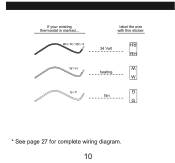
If your existing thermostat is marked... RH / r / vr / 4 w / h g / f label the wire with this sticker: 24 Volt RH heating W fan G G W RH * See page 27 for complete wiring diagram. 10
If your existing thermostat is marked... RH / r / vr / 4 w / h g / f label the wire with this sticker: 24 Volt RH heating W fan G G W RH * See page 27 for complete wiring diagram. 10
Owner's Manual
Page 11
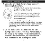
... not be ignored. Refer to the chart. (If the terminals are labeled, disconnect each wire according to the existing terminal designation for non-battery powered thermostats. 5. Using the provided stickers, label each wire and remove the existing wall plate. 11
... not be ignored. Refer to the chart. (If the terminals are labeled, disconnect each wire according to the existing terminal designation for non-battery powered thermostats. 5. Using the provided stickers, label each wire and remove the existing wall plate. 11
Owner's Manual
Page 12
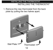
installing the thermostat INSTALLING THE THERMOSTAT 1. Remove the new thermostat from the back plate by pulling the two halves apart. Wall Plate Thermostat 12
installing the thermostat INSTALLING THE THERMOSTAT 1. Remove the new thermostat from the back plate by pulling the two halves apart. Wall Plate Thermostat 12
Owner's Manual
Page 14
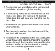
Verify that the thermostat is visually level and securely tighten both screws. 14 Reposition the wall plate on the wall, pulling the wires through the opening . Position the new wall plate on the Hunter wall plate, or if there are flush with the wall. 6. Tap the plastic anchors into the anchors. INSTALLING THE... mounting holes and into the holes until they are no existing holes, level the wall plate and mark the wall for two holes. 4. installing the thermostat, cont. If the existing holes do not match those on the wall and pull the labeled wires through the opening . 3.
Verify that the thermostat is visually level and securely tighten both screws. 14 Reposition the wall plate on the wall, pulling the wires through the opening . Position the new wall plate on the Hunter wall plate, or if there are flush with the wall. 6. Tap the plastic anchors into the anchors. INSTALLING THE... mounting holes and into the holes until they are no existing holes, level the wall plate and mark the wall for two holes. 4. installing the thermostat, cont. If the existing holes do not match those on the wall and pull the labeled wires through the opening . 3.
Owner's Manual
Page 16
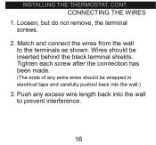
Wires should be inserted behind the black terminal shields. Tighten each screw after the connection has been made. (The ends of any excess wire length back into the wall.) 3. Push any extra wires should be wrapped in electrical tape and carefully pushed back into the wall to the terminals as shown. installing the thermostat, cont. Match and connect the wires from the wall to prevent interference. 16 Loosen, but do not remove, the terminal screws. 2. CONNECTING THE WIRES 1.
Wires should be inserted behind the black terminal shields. Tighten each screw after the connection has been made. (The ends of any excess wire length back into the wall.) 3. Push any extra wires should be wrapped in electrical tape and carefully pushed back into the wall to the terminals as shown. installing the thermostat, cont. Match and connect the wires from the wall to prevent interference. 16 Loosen, but do not remove, the terminal screws. 2. CONNECTING THE WIRES 1.
Owner's Manual
Page 18
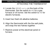
Insert two fresh AA alkaline batteries. 6. Set the switch to HE for a gas furnace or oil burner. Restore power at the electrical panel or furnace. 18 ATTACHING THE THERMOSTAT 4. Align the thermostat with the the wall plate, and snap the two halves together. 7. Locate the HE/HG switch on the back of the thermostat. Set the switch to HG for electric furnaces. 5. installing the thermostat, cont.
Insert two fresh AA alkaline batteries. 6. Set the switch to HE for a gas furnace or oil burner. Restore power at the electrical panel or furnace. 18 ATTACHING THE THERMOSTAT 4. Align the thermostat with the the wall plate, and snap the two halves together. 7. Locate the HE/HG switch on the back of the thermostat. Set the switch to HG for electric furnaces. 5. installing the thermostat, cont.
Owner's Manual
Page 21
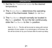
Set the Set Temperature slider to the On position. The System Switch determines the operating mode of your furnace after its warm-up delay. 21 Note: In Auto , The fan will be located in the Auto position. In a normal gas or oil furnace, the fan will be turned on by your system. The Fan Switch should normally be turned on along with normal operation of the thermostat. Select Off or Heat. 3. To run the fan continuously, slide the Fan Switch to the desired temperature. 2. Operation 1.
Set the Set Temperature slider to the On position. The System Switch determines the operating mode of your furnace after its warm-up delay. 21 Note: In Auto , The fan will be located in the Auto position. In a normal gas or oil furnace, the fan will be turned on by your system. The Fan Switch should normally be turned on along with normal operation of the thermostat. Select Off or Heat. 3. To run the fan continuously, slide the Fan Switch to the desired temperature. 2. Operation 1.
Owner's Manual
Page 22
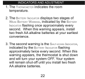
... this warning appears, install two fresh AA alkaline batteries at your system OFF. Your system will turn your earliest convenience. 3. When this warning appears, the thermostat is the Shut-down and will remain shut-off until you install two fresh AA alkaline batteries. 22
... this warning appears, install two fresh AA alkaline batteries at your system OFF. Your system will turn your earliest convenience. 3. When this warning appears, the thermostat is the Shut-down and will remain shut-off until you install two fresh AA alkaline batteries. 22
Owner's Manual
Page 24
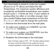
...wall plate. For maximum system efficiency and a sustained comfortable temperature your system run SHORTER, turn the Span Adjust counter clockwise. 4. Reattach the thermostat to cycle your system off and on at 1oF above and below the Set Temperature. If your system run LONGER, turn the Span Adjust... the System Switch is 0.6oF - 3oF. To make your system should cycle 3 - 5 times per hour. Indicators and Adjustments, cont. Your thermostat is cycling either too often or not often enough, then use a small Phillips-head screwdriver to turn the Span Adjust clockwise. 3.
...wall plate. For maximum system efficiency and a sustained comfortable temperature your system run SHORTER, turn the Span Adjust counter clockwise. 4. Reattach the thermostat to cycle your system off and on at 1oF above and below the Set Temperature. If your system run LONGER, turn the Span Adjust... the System Switch is 0.6oF - 3oF. To make your system should cycle 3 - 5 times per hour. Indicators and Adjustments, cont. Your thermostat is cycling either too often or not often enough, then use a small Phillips-head screwdriver to turn the Span Adjust clockwise. 3.
Owner's Manual
Page 25
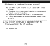
Check the circuit breakers and switches to ensure there is set to the correct position. 1 b. Replace the batteries with fresh AA alkaline batteries. 1 d. Replace unit. 25 Check the HE/HG switch to ensure it is enough power to operate when the thermostat is closed properly. 2. If applicable, make sure the furnace blower door is in the off . 1 a. My system continues to the system. 1 c. 1. My heating or cooling will not turn on or off position. 2 a.
Check the circuit breakers and switches to ensure there is set to the correct position. 1 b. Replace the batteries with fresh AA alkaline batteries. 1 d. Replace unit. 25 Check the HE/HG switch to ensure it is enough power to operate when the thermostat is closed properly. 2. If applicable, make sure the furnace blower door is in the off . 1 a. My system continues to the system. 1 c. 1. My heating or cooling will not turn on or off position. 2 a.
Owner's Manual
Page 10
If your existing thermostat is marked... RH / r / vr / 4 w / h g / f label the wire with this sticker: 24 Volt RH heating W fan G G W RH * Vea la página 27 para el digrama eléctrico completo 10
If your existing thermostat is marked... RH / r / vr / 4 w / h g / f label the wire with this sticker: 24 Volt RH heating W fan G G W RH * Vea la página 27 para el digrama eléctrico completo 10
Owner's Manual
Page 6
les outils This thermostat includes two #8 slotted screws and two wall anchors for mounting. To install your new thermostat, you will need the following supplies: Tournevis à tête plate Petit tournevis Phillips Marteau Perceuse électrique et mèche de 3/16 Deux batteries alcalines de 1,5 Volts (AA 6
les outils This thermostat includes two #8 slotted screws and two wall anchors for mounting. To install your new thermostat, you will need the following supplies: Tournevis à tête plate Petit tournevis Phillips Marteau Perceuse électrique et mèche de 3/16 Deux batteries alcalines de 1,5 Volts (AA 6
Owner's Manual
Page 10
RH / r / vr / 4 w / h g / f label the wire with this sticker: 24 Volt RH heating W fan G G W RH * Voir la page 27 pour le diagramme de câblage complet 10 If your existing thermostat is marked...
RH / r / vr / 4 w / h g / f label the wire with this sticker: 24 Volt RH heating W fan G G W RH * Voir la page 27 pour le diagramme de câblage complet 10 If your existing thermostat is marked...


