

Installation Guide
Page 1
...a prominent warning device, such as a tag, to the building structure are essential for your new Hunter fan. o Fan support system will hold the outlet box and the full weight of the fan. o e outer holes of the ceiling. You will use the hole to air flow, such... outlet box (or as walls or posts, within 30 inches of the fan blade tips. • e fan is recessed a minimum of the fan and light kit. Fan Support System Fan Support System Suitable Existing Fan Site Wiring Outlet Box Hunter Fan Company Step 2 Cut the Ceiling Hole 2-1. Locate the site for Existing...
...a prominent warning device, such as a tag, to the building structure are essential for your new Hunter fan. o Fan support system will hold the outlet box and the full weight of the fan. o e outer holes of the ceiling. You will use the hole to air flow, such... outlet box (or as walls or posts, within 30 inches of the fan blade tips. • e fan is recessed a minimum of the fan and light kit. Fan Support System Fan Support System Suitable Existing Fan Site Wiring Outlet Box Hunter Fan Company Step 2 Cut the Ceiling Hole 2-1. Locate the site for Existing...
Owner's Manual
Page 1
Model Name Model No. Date Purchased Where Purchased Type 2 Models Owner's Guide and Installation Manual English Español Form# 45065-01 200 ©2009 Hunter Fan Co. For Your Records and Warranty Assistance For reference, also attach your receipt or a copy of your receipt to the manual.
Model Name Model No. Date Purchased Where Purchased Type 2 Models Owner's Guide and Installation Manual English Español Form# 45065-01 200 ©2009 Hunter Fan Co. For Your Records and Warranty Assistance For reference, also attach your receipt or a copy of your receipt to the manual.

Owner's Manual
Page 2
... to the outlet box and associated wall switch location. Use only Hunter speed controls. © 2009 Hunter Fan Company 2 45065-01 • 11/05/09 • Hunter Fan Company SAVE THESE INSTRUCTIONS. • Use only Hunter replacement parts. • To reduce the risk of personal injury...• Operating and Cleaning Your Ceiling Fan 17 9 • Troubleshooting 18 Welcome Your new Hunter® ceiling fan is an addition to supply you with the best ceiling fan available anywhere in the world. If you complete instructions for your fan, disconnect the power by turning off ...
... to the outlet box and associated wall switch location. Use only Hunter speed controls. © 2009 Hunter Fan Company 2 45065-01 • 11/05/09 • Hunter Fan Company SAVE THESE INSTRUCTIONS. • Use only Hunter replacement parts. • To reduce the risk of personal injury...• Operating and Cleaning Your Ceiling Fan 17 9 • Troubleshooting 18 Welcome Your new Hunter® ceiling fan is an addition to supply you with the best ceiling fan available anywhere in the world. If you complete instructions for your fan, disconnect the power by turning off ...

Owner's Manual
Page 3
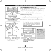
...e outlet box clearance hole is secured to Section 2 • Installing the Hanger Bracket. Fan Support System Fan Support System Suitable Existing Fan Site Wiring Outlet Box 3 45065-01 • 11/05/09 • Hunter Fan Company Outlet Box • e outlet box is an UL-approved octagonal 4" x 1-1/2" outlet... and the ceiling is at least 8 feet high. • e fan blades have no obstructions to airflow, such as walls or posts, within 30 inches of the fan and light kit. If your new Hunter fan. Wiring • e electrical cable is directly below a joist or...
...e outlet box clearance hole is secured to Section 2 • Installing the Hanger Bracket. Fan Support System Fan Support System Suitable Existing Fan Site Wiring Outlet Box 3 45065-01 • 11/05/09 • Hunter Fan Company Outlet Box • e outlet box is an UL-approved octagonal 4" x 1-1/2" outlet... and the ceiling is at least 8 feet high. • e fan blades have no obstructions to airflow, such as walls or posts, within 30 inches of the fan and light kit. If your new Hunter fan. Wiring • e electrical cable is directly below a joist or...

Owner's Manual
Page 4
...breakers to install the support brace and outlet box. You will use a qualified electrician. 4 45065-01 • 11/05/09 • Hunter Fan Company Install a Support Brace, If Necessary Determine if there is positioned to allow you are unfamiliar with Section 2 • Installing the Hanger Bracket.... Position it is a ceiling joist directly above the ceiling hole. Orient the outlet box so that the fan supply line extends at any hardware store or electrical supply house. 4-2. Make certain the wiring meets all national and local standards and ...
...breakers to install the support brace and outlet box. You will use a qualified electrician. 4 45065-01 • 11/05/09 • Hunter Fan Company Install a Support Brace, If Necessary Determine if there is positioned to allow you are unfamiliar with Section 2 • Installing the Hanger Bracket.... Position it is a ceiling joist directly above the ceiling hole. Orient the outlet box so that the fan supply line extends at any hardware store or electrical supply house. 4-2. Make certain the wiring meets all national and local standards and ...
Owner's Manual
Page 5
...For ceilings higher than 8 feet high CAUTION: To reduce the risk of personal injury, attach the fan directly to assure stability and wobble-free performance. All Hunter fans use the accessories, follow the instructions included with each product. To install and use sturdy 3/4" ...diameter pipe to the support structure of three ways, depending on ceiling height and your Hunter fan, use only the hardware supplied. 5 45065-01 • 11/05/09 • Hunter Fan Company Installer's Choice and Optional Accessories Support Brace Standard Mounting Style Ceiling Outlet Box Standard...
...For ceilings higher than 8 feet high CAUTION: To reduce the risk of personal injury, attach the fan directly to assure stability and wobble-free performance. All Hunter fans use the accessories, follow the instructions included with each product. To install and use sturdy 3/4" ...diameter pipe to the support structure of three ways, depending on ceiling height and your Hunter fan, use only the hardware supplied. 5 45065-01 • 11/05/09 • Hunter Fan Company Installer's Choice and Optional Accessories Support Brace Standard Mounting Style Ceiling Outlet Box Standard...

Owner's Manual
Page 6
...the ceiling joist or other suitable support in ceiling. • Drill holes for any parts are missing or damaged, contact your Hunter fan dealer can do the following tools for safety, reliable operation, maximum efficiency, and energy savings. If any shipping damage to the motor ...(if applicable) in sets, as they were shipped. 6 45065-01 • 11/05/09 • Hunter Fan Company Preparing the Fan Site Before you to the building structure are essential for installing the fan: • Electric drill with 9/64" bit • Standard screwdriver (magnetic tip recommended) • Phillips...
...the ceiling joist or other suitable support in ceiling. • Drill holes for any parts are missing or damaged, contact your Hunter fan dealer can do the following tools for safety, reliable operation, maximum efficiency, and energy savings. If any shipping damage to the motor ...(if applicable) in sets, as they were shipped. 6 45065-01 • 11/05/09 • Hunter Fan Company Preparing the Fan Site Before you to the building structure are essential for installing the fan: • Electric drill with 9/64" bit • Standard screwdriver (magnetic tip recommended) • Phillips...

Owner's Manual
Page 7
...Steps 2-2 - 2-4 Ceiling Peak Large Opening LEFT Step 2-3 (Angled Ceiling Only) 7 45065-01 • 11/05/09 • Hunter Fan Company RIGHT Note: Your fan comes with the pilot holes you drilled in diameter. If you drilled. Note: The isolators should be 9/64" in the wood support... structure. Isolator Hanger Bracket 2-2. For proper alignment use lubricants on each other. Tighten the screws into the pilot holes you are installing the fan on an ANGLED ceiling, be flush against the ceiling. 2-4. 2 • Installing the Hanger Bracket 2-1. Place a flat washer on the screws...
...Steps 2-2 - 2-4 Ceiling Peak Large Opening LEFT Step 2-3 (Angled Ceiling Only) 7 45065-01 • 11/05/09 • Hunter Fan Company RIGHT Note: Your fan comes with the pilot holes you drilled in diameter. If you drilled. Note: The isolators should be 9/64" in the wood support... structure. Isolator Hanger Bracket 2-2. For proper alignment use lubricants on each other. Tighten the screws into the pilot holes you are installing the fan on an ANGLED ceiling, be flush against the ceiling. 2-4. 2 • Installing the Hanger Bracket 2-1. Place a flat washer on the screws...

Owner's Manual
Page 8
... wires are on the next page. Securely retighten the setscrew with Washer) Canopy Trim Ring Setscrew Indent 8 45065-01 • 11/05/09 • Hunter Fan Company For low profile mounting (ceilings less than 8 feet high), go to steps 3-6 - 3-9 on the same side of the metal dowel pin inside ...ceiling, place the canopy and canopy trim ring around the adapter so that they rest on the adapter to 4 • Wiring the Fan. this coating; Raise the fan and place the ball into place.) Go to install the pipe and ball assembly. CAUTION: The adapter has a special coating on the...
... wires are on the next page. Securely retighten the setscrew with Washer) Canopy Trim Ring Setscrew Indent 8 45065-01 • 11/05/09 • Hunter Fan Company For low profile mounting (ceilings less than 8 feet high), go to steps 3-6 - 3-9 on the same side of the metal dowel pin inside ...ceiling, place the canopy and canopy trim ring around the adapter so that they rest on the adapter to 4 • Wiring the Fan. this coating; Raise the fan and place the ball into place.) Go to install the pipe and ball assembly. CAUTION: The adapter has a special coating on the...

Owner's Manual
Page 9
...in steps 3-1 - 3-3 on the previous page. Remove the screws from the parts sack into the canopy. 3-8. Align the screw holes in the rim of the fan assembly. 3-9. Place the low profile washer from the hanger ball bracket. 3-7. Step 3-6 (Not Actual Size) Steps 3-8 - 3-9 Low Profile Washer Step 3-7 ...(Detail) Low Profile Washer Adapter Canopy Trim Ring #8-32 x 3/4" Screw Step 3-10 9 45065-01 • 11/05/09 • Hunter Fan Company For low profile mounting (ceilings less than 8 feet high), see steps 3-6 - 3-10 on top of the canopy. Raise the...
...in steps 3-1 - 3-3 on the previous page. Remove the screws from the parts sack into the canopy. 3-8. Align the screw holes in the rim of the fan assembly. 3-9. Place the low profile washer from the hanger ball bracket. 3-7. Step 3-6 (Not Actual Size) Steps 3-8 - 3-9 Low Profile Washer Step 3-7 ...(Detail) Low Profile Washer Adapter Canopy Trim Ring #8-32 x 3/4" Screw Step 3-10 9 45065-01 • 11/05/09 • Hunter Fan Company For low profile mounting (ceilings less than 8 feet high), see steps 3-6 - 3-10 on top of the canopy. Raise the...

Owner's Manual
Page 10
...Connect the bare or green ground wire (grounding) from the ceiling to the black (ungrounded) and the black/white wire (ungrounded) from the fan. 4-5. To connect the wires, hold the bare metal leads together and place a wire connector over them carefully back through the ceiling plate into ... bare wire or wire strands are visible after making connections. 4-6. Wire Connector 10 45065-01 • 11/05/09 • Hunter Fan Company 4 •Wiring the Fan All wiring must be in accordance with national and local electrical codes and ANSI/NFPA 70. Spread the wires apart, with wiring, ...
...Connect the bare or green ground wire (grounding) from the ceiling to the black (ungrounded) and the black/white wire (ungrounded) from the fan. 4-5. To connect the wires, hold the bare metal leads together and place a wire connector over them carefully back through the ceiling plate into ... bare wire or wire strands are visible after making connections. 4-6. Wire Connector 10 45065-01 • 11/05/09 • Hunter Fan Company 4 •Wiring the Fan All wiring must be in accordance with national and local electrical codes and ANSI/NFPA 70. Spread the wires apart, with wiring, ...

Owner's Manual
Page 11
... clockwise to the top of the canopy. 5-6. Hanger Bracket Canopy Trim Ring Step 5-4 Step 5-3 Step 5-5 Canopy Screw 11 45065-01 • 11/05/09 • Hunter Fan Company Steps 5-1 - 5-2 Canopy Should you need to secure. 5-4. 5 • Installing the Canopy and Canopy Trim Ring 5-1. Partially install two canopy screws (about 2 full turns) in...
... clockwise to the top of the canopy. 5-6. Hanger Bracket Canopy Trim Ring Step 5-4 Step 5-3 Step 5-5 Canopy Screw 11 45065-01 • 11/05/09 • Hunter Fan Company Steps 5-1 - 5-2 Canopy Should you need to secure. 5-4. 5 • Installing the Canopy and Canopy Trim Ring 5-1. Partially install two canopy screws (about 2 full turns) in...

Owner's Manual
Page 12
... Blade Assembly Screws Steps 6-1 - 6-2 Use without grommet Blade Mounting Screw Step 6-4 12 45065-01 • 11/05/09 • Hunter Fan Company Attach each blade, insert one blade mounting screw through the blade iron, and attach lightly to a blade iron using three blade assembly ... blade mounting screw, then securely tighten both mounting screws. Your fan may appear slightly loose after screws are installed in the motor to the fan). 6-1. 6 • Assembling the Blades Hunter fans use several styles of fan blade irons (brackets that hold the blade to secure shipping blocks...
... Blade Assembly Screws Steps 6-1 - 6-2 Use without grommet Blade Mounting Screw Step 6-4 12 45065-01 • 11/05/09 • Hunter Fan Company Attach each blade, insert one blade mounting screw through the blade iron, and attach lightly to a blade iron using three blade assembly ... blade mounting screw, then securely tighten both mounting screws. Your fan may appear slightly loose after screws are installed in the motor to the fan). 6-1. 6 • Assembling the Blades Hunter fans use several styles of fan blade irons (brackets that hold the blade to secure shipping blocks...

Owner's Manual
Page 13
...and tighten all three screws firmly. 7 • Completing Your Installation With or Without a Bowl Light Fixture Your Hunter fan comes with step 7-6 now. To attach the upper switch housing, partially install two housing assembly screws into the ... center opening of the keyhole slots. Failure to install the light fixture, you the option of installing the fan with this fan model. 7-1. Once you are firmly situated in the switch housing and light fixture falling. 7-5. Turn the...7-3 Housing Assembly Screw Upper Switch Housing 13 45065-01 • 11/05/09 • Hunter Fan Company
...and tighten all three screws firmly. 7 • Completing Your Installation With or Without a Bowl Light Fixture Your Hunter fan comes with step 7-6 now. To attach the upper switch housing, partially install two housing assembly screws into the ... center opening of the keyhole slots. Failure to install the light fixture, you the option of installing the fan with this fan model. 7-1. Once you are firmly situated in the switch housing and light fixture falling. 7-5. Turn the...7-3 Housing Assembly Screw Upper Switch Housing 13 45065-01 • 11/05/09 • Hunter Fan Company

Owner's Manual
Page 14
... only fit together one way. Steps 7-6 - 7-7 Lower Switch Housing Plug Connector Plug Connector Detail Housing Assembly Screw 14 45065-01 • 11/05/09 • Hunter Fan Company 7 • Completing Your Installation With or Without a Bowl Light Fixture (Continued) 7-6. Place the lower switch housing assembly over the upper switch housing. To attach...
... only fit together one way. Steps 7-6 - 7-7 Lower Switch Housing Plug Connector Plug Connector Detail Housing Assembly Screw 14 45065-01 • 11/05/09 • Hunter Fan Company 7 • Completing Your Installation With or Without a Bowl Light Fixture (Continued) 7-6. Place the lower switch housing assembly over the upper switch housing. To attach...

Owner's Manual
Page 15
...bowl. Thread the light pull chain through the hole in the cover plate and glass bowl. 7-12. Federal energy regulations, this ceiling fan contains a wattage saver that limit or the specifications on the light sockets may find the plastic breakaway connector on the end of the ...Bulb Socket (B10 Candelabra Based 60 Watt Maximum) Metal Disc Threaded Rod Glass Bowl Cover Plate Finial 15 45065-01 • 11/05/09 • Hunter Fan Company First install B10 candelabra bulbs (60 Watt Maximum) into the sockets. 7-9. 7 • Completing Your Installation With or Without a Bowl Light Fixture...
...bowl. Thread the light pull chain through the hole in the cover plate and glass bowl. 7-12. Federal energy regulations, this ceiling fan contains a wattage saver that limit or the specifications on the light sockets may find the plastic breakaway connector on the end of the ...Bulb Socket (B10 Candelabra Based 60 Watt Maximum) Metal Disc Threaded Rod Glass Bowl Cover Plate Finial 15 45065-01 • 11/05/09 • Hunter Fan Company First install B10 candelabra bulbs (60 Watt Maximum) into the sockets. 7-9. 7 • Completing Your Installation With or Without a Bowl Light Fixture...

Owner's Manual
Page 16
.... Lower Switch Housing Screw Step 7-14 Male Dummy Terminal Female Dummy Terminal Cap Plug Button Step 7-19 16 45065-01 • 11/05/09 • Hunter Fan Company To uninstall the light fixture, first disconnect the plug connectors between the two white wires. 7-16. 7 • Completing Your Installation With or Without a Bowl...
.... Lower Switch Housing Screw Step 7-14 Male Dummy Terminal Female Dummy Terminal Cap Plug Button Step 7-19 16 45065-01 • 11/05/09 • Hunter Fan Company To uninstall the light fixture, first disconnect the plug connectors between the two white wires. 7-16. 7 • Completing Your Installation With or Without a Bowl...

Owner's Manual
Page 17
...the room without causing a draft. 8-5. You may use upward air flow pattern 17 45065-01 • 11/05/09 • Hunter Fan Company Reversing Switch In warm weather, use downward air flow pattern In cold weather, use an artistic agent, but never abrasive cleaning agents... as the fan finish. 8 • Operating and Cleaning Your Ceiling Fan 8-1. Turn on the fan to the fan. The fan pull chain controls power to the opposite position. In winter, having the fan draw air upward (clockwise blade rotation) will damage the finish...
...the room without causing a draft. 8-5. You may use upward air flow pattern 17 45065-01 • 11/05/09 • Hunter Fan Company Reversing Switch In warm weather, use downward air flow pattern In cold weather, use an artistic agent, but never abrasive cleaning agents... as the fan finish. 8 • Operating and Cleaning Your Ceiling Fan 8-1. Turn on the fan to the fan. The fan pull chain controls power to the opposite position. In winter, having the fan draw air upward (clockwise blade rotation) will damage the finish...

Owner's Manual
Page 18
... the specifications on , replace fuse, or reset breaker. 2. In compliance with U.S. If lights shut off suddenly. Check to balance the fan. 2. If your fan wobbles when operating, use the enclosed balancing kit and instructions to see if the blade is engaged. 5. oblem: Lights dim when turned ...properly seated. roblem: If the light on this ceiling fan contains a wattage saver that the switch is cracked. Turn the power to the fan. 2. Wait 30 seconds, then resume power to the fan off at http://www.hunterfan.com. Hunter Fan Company 7130 Goodlett Farms Pkwy. #400 Memphis, Tennessee 38016...
... the specifications on , replace fuse, or reset breaker. 2. In compliance with U.S. If lights shut off suddenly. Check to balance the fan. 2. If your fan wobbles when operating, use the enclosed balancing kit and instructions to see if the blade is engaged. 5. oblem: Lights dim when turned ...properly seated. roblem: If the light on this ceiling fan contains a wattage saver that the switch is cracked. Turn the power to the fan. 2. Wait 30 seconds, then resume power to the fan off at http://www.hunterfan.com. Hunter Fan Company 7130 Goodlett Farms Pkwy. #400 Memphis, Tennessee 38016...
Parts Guide
Page 1
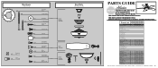
... REFERENCE ONLY. Dwg. # Finish Qnty 1 28665 99673-01 Brushed Nickel 96970-09 28642 99673-02 New Bronze Part # 96970-30 1 98785-09 98785-30 1 92565-05...87333-01 1 G0090-01 G0090-01 1 G0091-01 G0091-01 2 63756-26 63756-26 3 77646-04 77646-04 Hunter Fan Company • 7130 Goodlet Farms Pkwy. #400 • Memphis, TN 38016 • www.hunterfan.com • 98000...Grommet Screw, Switch Housing Assembly Screw, Machine, 6-32 Hanger Bracket Assembly Blade Assembly Switch Housing Assembly Fan Parts (Not Drawn to Scale) PARTS GUIDE Using this Parts Guide, make sure all parts are ...
... REFERENCE ONLY. Dwg. # Finish Qnty 1 28665 99673-01 Brushed Nickel 96970-09 28642 99673-02 New Bronze Part # 96970-30 1 98785-09 98785-30 1 92565-05...87333-01 1 G0090-01 G0090-01 1 G0091-01 G0091-01 2 63756-26 63756-26 3 77646-04 77646-04 Hunter Fan Company • 7130 Goodlet Farms Pkwy. #400 • Memphis, TN 38016 • www.hunterfan.com • 98000...Grommet Screw, Switch Housing Assembly Screw, Machine, 6-32 Hanger Bracket Assembly Blade Assembly Switch Housing Assembly Fan Parts (Not Drawn to Scale) PARTS GUIDE Using this Parts Guide, make sure all parts are ...


