
Installation Guide
Page 1
o e outlet box is an UL-approved octagonal 4" x 1-1/2" outlet box (or as specified by the support brace manufacturer). Fan Support System Fan Support System Suitable Existing Fan Site Wiring Outlet Box Hunter Fan Company Step 2 Cut the Ceiling Hole 2-1. If the joist is there, determine if it to allow you to recess the bottom of the outlet...
o e outlet box is an UL-approved octagonal 4" x 1-1/2" outlet box (or as specified by the support brace manufacturer). Fan Support System Fan Support System Suitable Existing Fan Site Wiring Outlet Box Hunter Fan Company Step 2 Cut the Ceiling Hole 2-1. If the joist is there, determine if it to allow you to recess the bottom of the outlet...

Owner's Manual
Page 1
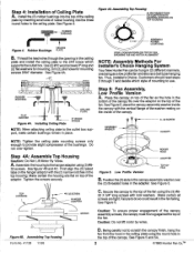
... FOR HUNTER CEILING FANS USING INSTALLER'S CHOICE MOUNTINGS READ AND SAVE THESE INSTRUCTIONS CAUTION 1. ifyouam unfamiliar with wiring, youshould use no object can be in Wiring. To reduce the risk ofpersonal injury, do not bend the blade brackets wheninstalling the brackets orcleaning the fan. Select..." CLEARANCE TO OBSTRUCTIONS no larger than one of Fan A. A. Caution: Do not use two #8 x 1-1/2" wood screws and washers. If more than the minor diameter of parts. CEILING OUTLET BOX Figure 2. S. 0 :0 ." Use Hunter Controls only. 2. B. Use the innermost holes ...
... FOR HUNTER CEILING FANS USING INSTALLER'S CHOICE MOUNTINGS READ AND SAVE THESE INSTRUCTIONS CAUTION 1. ifyouam unfamiliar with wiring, youshould use no object can be in Wiring. To reduce the risk ofpersonal injury, do not bend the blade brackets wheninstalling the brackets orcleaning the fan. Select..." CLEARANCE TO OBSTRUCTIONS no larger than one of Fan A. A. Caution: Do not use two #8 x 1-1/2" wood screws and washers. If more than the minor diameter of parts. CEILING OUTLET BOX Figure 2. S. 0 :0 ." Use Hunter Controls only. 2. B. Use the innermost holes ...
Owner's Manual
Page 2
... O 0 O SLAOCSCRSEAEMTWIBOLNYS SVIHEOWW: LIONGOTKAINBGADNODWNONTOCNHTAOLPIGONFMFAENNT NOTE: Assembly Methods For Installer's Choice Hanging System Your New Hunter Fan can be hung in the top housing. place the canopy assembly washer inside of the canopy. 8.32 SCREW WASASSHEEMRBLY CANOPY NOTE: Tighten the ceiling plate mounting screws only enough to the 2X4 brace which style of mounting to...
... O 0 O SLAOCSCRSEAEMTWIBOLNYS SVIHEOWW: LIONGOTKAINBGADNODWNONTOCNHTAOLPIGONFMFAENNT NOTE: Assembly Methods For Installer's Choice Hanging System Your New Hunter Fan can be hung in the top housing. place the canopy assembly washer inside of the canopy. 8.32 SCREW WASASSHEEMRBLY CANOPY NOTE: Tighten the ceiling plate mounting screws only enough to the 2X4 brace which style of mounting to...
Owner's Manual
Page 3
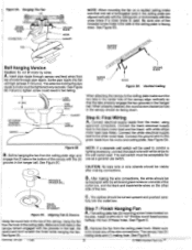
... located on the other side of motor through canopy and feed wires from the motor and ceiling plate. -I Figure 5A. WIRE CONNECTOR FAN /" / CEILING PLATE HOOK CANOPY NOTE: When mounting the fan on a vaulted ceiling make sure the two tabs in the center hole of the canopy align vertically so that ...screw could result in the top of the wire connections. Connect the white electrical supply lead to break any of the canopy, hang the fan from the ceiling plate hook. Connect the ground wire to the wall switch lead. See Figure 5A. Figure 5B B. CD GROOVE IN HANGER BALL NOTE...
... located on the other side of motor through canopy and feed wires from the motor and ceiling plate. -I Figure 5A. WIRE CONNECTOR FAN /" / CEILING PLATE HOOK CANOPY NOTE: When mounting the fan on a vaulted ceiling make sure the two tabs in the center hole of the canopy align vertically so that ...screw could result in the top of the wire connections. Connect the white electrical supply lead to break any of the canopy, hang the fan from the ceiling plate hook. Connect the ground wire to the wall switch lead. See Figure 5A. Figure 5B B. CD GROOVE IN HANGER BALL NOTE...
Owner's Manual
Page 5
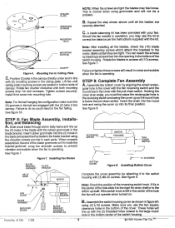
...belly band and line up draft. STEP 9: Complete Fan Assembly A. Slide wood blade through slot in the blade bracket. Failure to the motor. When properly assembled, the end of the switch housing. 4 ©1993 Hunter Firi CEILING PLATE MOUNTING SCREWS MOUNTING HOLE MOUNTING SLOTS (2) CANOPY ...Figure G. Lift fan until both mounting screws drop Into slot recesses. Assemble the bottom cover by aligning the small rectan- ...
...belly band and line up draft. STEP 9: Complete Fan Assembly A. Slide wood blade through slot in the blade bracket. Failure to the motor. When properly assembled, the end of the switch housing. 4 ©1993 Hunter Firi CEILING PLATE MOUNTING SCREWS MOUNTING HOLE MOUNTING SLOTS (2) CANOPY ...Figure G. Lift fan until both mounting screws drop Into slot recesses. Assemble the bottom cover by aligning the small rectan- ...
Owner's Manual
Page 6
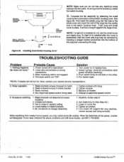
... close to one side or the other. 4. Tighten all blades. 4. Form No. 41128 11/93 5 ©1993 Hunter Fan Co.TM SWITCH HOUSING COVER SWITCH L HOUSING USE SQUARE HOLES SMALL SWITCH HOUSING COVER 32 SCREWS (2) r im- loosen canopy, check all connections (tu'rn ... NOTE: Make sure you do not use the small cover and plastic plug. Motor reversing switch not engaged 4. Push switch firmly to vaulted ceiling. 4. Nothing Happens fan does not move fan. 4. Use balancing kit (See Step 8C) 3. If a light kit is installed after the cover is assembled, then the cover and plug ...
... close to one side or the other. 4. Tighten all blades. 4. Form No. 41128 11/93 5 ©1993 Hunter Fan Co.TM SWITCH HOUSING COVER SWITCH L HOUSING USE SQUARE HOLES SMALL SWITCH HOUSING COVER 32 SCREWS (2) r im- loosen canopy, check all connections (tu'rn ... NOTE: Make sure you do not use the small cover and plastic plug. Motor reversing switch not engaged 4. Push switch firmly to vaulted ceiling. 4. Nothing Happens fan does not move fan. 4. Use balancing kit (See Step 8C) 3. If a light kit is installed after the cover is assembled, then the cover and plug ...
Parts Guide
Page 1
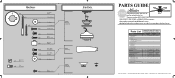
...Qnty 1 25866 93738-04 Gloss White Part # 94945-03 25867 93738-06 Brushed Nickel Part # 94945-09 6 74508-36 74508-36 1 G0677-13 G0677-45 11 63755-05 63755-05 1 84007-01 84007-01 1 96757-01 96757-01 1 93738-00-863 93738-05-865 1 07570-01 07570-01 Hunter Fan Company ..., call 888-830-1326 for assistance. REFER TO THE INSTALLATION MANUAL FOR FULL ASSEMBLY INSTRUCTIONS. Parts List Item Name * Hanging System Kit Ceiling Plate Canopy Canopy Trim Ring Hanger Ball / Downrod Assembly Low Profile Washer Canopy Screw Wood Screw Flat Washer Mounting Isolator * Locking Screw Machine...
...Qnty 1 25866 93738-04 Gloss White Part # 94945-03 25867 93738-06 Brushed Nickel Part # 94945-09 6 74508-36 74508-36 1 G0677-13 G0677-45 11 63755-05 63755-05 1 84007-01 84007-01 1 96757-01 96757-01 1 93738-00-863 93738-05-865 1 07570-01 07570-01 Hunter Fan Company ..., call 888-830-1326 for assistance. REFER TO THE INSTALLATION MANUAL FOR FULL ASSEMBLY INSTRUCTIONS. Parts List Item Name * Hanging System Kit Ceiling Plate Canopy Canopy Trim Ring Hanger Ball / Downrod Assembly Low Profile Washer Canopy Screw Wood Screw Flat Washer Mounting Isolator * Locking Screw Machine...


