
Installation Guide
Page 1
... or electrical supply house. 5-4. Step 5 Step 5 Prepare the Wiring 5-1. For instructions to install your ceiling fan, go to your fan manual and continue with an approved connector, available at least 7 feet above the ceiling hole. Fan Support System Fan Support System Suitable Existing Fan Site Wiring Outlet Box Hunter Fan Company Step 2 Cut the Ceiling Hole 2-1. Attach the fan supply line to your fan manual and begin with two #8 x 1-1/2" wood screws and washers. e bottom of the outlet box must...
... or electrical supply house. 5-4. Step 5 Step 5 Prepare the Wiring 5-1. For instructions to install your ceiling fan, go to your fan manual and continue with an approved connector, available at least 7 feet above the ceiling hole. Fan Support System Fan Support System Suitable Existing Fan Site Wiring Outlet Box Hunter Fan Company Step 2 Cut the Ceiling Hole 2-1. Attach the fan supply line to your fan manual and begin with two #8 x 1-1/2" wood screws and washers. e bottom of the outlet box must...

Owner's Manual
Page 1
Model Name Model No. Date Purchased Where Purchased Type 2 Models Owner's Guide and Installation Manual English Español Form# 45022-01 20101015 ©2010 Hunter Fan Co. For Your Records and Warranty Assistance For reference, also attach your receipt or a copy of your receipt to the manual.
Model Name Model No. Date Purchased Where Purchased Type 2 Models Owner's Guide and Installation Manual English Español Form# 45022-01 20101015 ©2010 Hunter Fan Co. For Your Records and Warranty Assistance For reference, also attach your receipt or a copy of your receipt to the manual.
Owner's Manual
Page 2
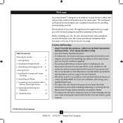
... bend the blade attachment system when installing, balancing, or cleaning the fan. Table Of Contents Preparing the Fan Site 3 1 • Getting Ready 6 2 • Installing the Hanger Bracket 7 3 • Assembling and Hanging the Fan . . . . 8 4 •Wiring the Fan 10 5 • Installing the Canopy and Canopy Trim Ring 11 6 • Assembling the Blades 12 7 • Completing Your Installation With or Without a Bowl Light Fixture 13 8 • Operating and Cleaning Your Ceiling Fan 17 9 • Troubleshooting 18 Welcome Your new Hunter® ceiling fan is an...
... bend the blade attachment system when installing, balancing, or cleaning the fan. Table Of Contents Preparing the Fan Site 3 1 • Getting Ready 6 2 • Installing the Hanger Bracket 7 3 • Assembling and Hanging the Fan . . . . 8 4 •Wiring the Fan 10 5 • Installing the Canopy and Canopy Trim Ring 11 6 • Assembling the Blades 12 7 • Completing Your Installation With or Without a Bowl Light Fixture 13 8 • Operating and Cleaning Your Ceiling Fan 17 9 • Troubleshooting 18 Welcome Your new Hunter® ceiling fan is an...
Owner's Manual
Page 3
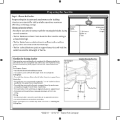
... off every item, prepare a new fan site as specified by an approved connector. • Six inches of the fan. 30" From Wall or Nearest Obstruction 7' Minimum Blades to Section 2 • Installing the Ceiling Plate. Fan Support System Fan Support System Suitable Existing Fan Site Wiring Outlet Box 3 45022-01 • 10/15/10 • Hunter Fan Company Wiring • e electrical cable is suitable, skip ahead to Floor 8' Minimum Ceiling Height Checklist for your...
... off every item, prepare a new fan site as specified by an approved connector. • Six inches of the fan. 30" From Wall or Nearest Obstruction 7' Minimum Blades to Section 2 • Installing the Ceiling Plate. Fan Support System Fan Support System Suitable Existing Fan Site Wiring Outlet Box 3 45022-01 • 10/15/10 • Hunter Fan Company Wiring • e electrical cable is suitable, skip ahead to Floor 8' Minimum Ceiling Height Checklist for your...
Owner's Manual
Page 4
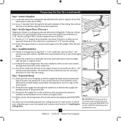
... washers. e bottom of the outlet box must be in the box align with Section 2 • Installing the Ceiling Plate. Step 3 - Attach a 2" x 4" support brace between two joists. Position it is a ceiling joist directly above the ceiling hole. Step 4 - Obtain a UL-approved octagonal 4" x 1-1/2" outlet box, plus two #8 x 1-1/2" wood screws and washers, available from any hardware store or electrical supply house. 5-4. Step 5 - For instructions to install your ceiling fan, go to install the support...
... washers. e bottom of the outlet box must be in the box align with Section 2 • Installing the Ceiling Plate. Step 3 - Attach a 2" x 4" support brace between two joists. Position it is a ceiling joist directly above the ceiling hole. Step 4 - Obtain a UL-approved octagonal 4" x 1-1/2" outlet box, plus two #8 x 1-1/2" wood screws and washers, available from any hardware store or electrical supply house. 5-4. Step 5 - For instructions to install your ceiling fan, go to install the support...
Owner's Manual
Page 5
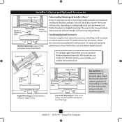
... Mounting Style 8 12 Angled Mounting recommended for a vaulted or angled ceiling Support Brace Low Profile Mounting Style Ceiling Outlet Box Low Profile Mounting fits close to these instructions, and use only Hunter speed controls. The steps in one of three ways, depending on ceiling height and your Hunter fan, use only the hardware supplied. 5 45022-01 • 10/15/10 • Hunter Fan Company Considering Optional Accessories Consider using Hunter's optional accessories, including a wall-mounted or remote speed control. You can purchase Hunter extension downrods...
... Mounting Style 8 12 Angled Mounting recommended for a vaulted or angled ceiling Support Brace Low Profile Mounting Style Ceiling Outlet Box Low Profile Mounting fits close to these instructions, and use only Hunter speed controls. The steps in one of three ways, depending on ceiling height and your Hunter fan, use only the hardware supplied. 5 45022-01 • 10/15/10 • Hunter Fan Company Considering Optional Accessories Consider using Hunter's optional accessories, including a wall-mounted or remote speed control. You can purchase Hunter extension downrods...
Owner's Manual
Page 6
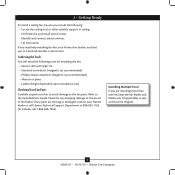
... Tools You will need help installing the fan, your Hunter fan dealer can do the following tools for and install wood screws. • Identify and connect electrical wires. • Lift 40 pounds. Refer to the motor or fan blades. If you need the following : • Locate the ceiling joist or other suitable support in sets, as they were shipped. 6 45022-01 • 10/15/10 • Hunter Fan Company Installing Multiple Fans? If you are...
... Tools You will need help installing the fan, your Hunter fan dealer can do the following tools for and install wood screws. • Identify and connect electrical wires. • Lift 40 pounds. Refer to the motor or fan blades. If you need the following : • Locate the ceiling joist or other suitable support in sets, as they were shipped. 6 45022-01 • 10/15/10 • Hunter Fan Company Installing Multiple Fans? If you are...
Owner's Manual
Page 7
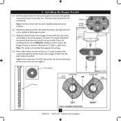
... the hanger bracket as shown in the outlet box. Thread the lead wires from each of the hanger bracket. 2-3. Tighten the screws into the pilot holes you drilled in the hanger bracket with four pre-installed neoprene noise isolators. Do not over tighten. 3" Screw Flat Washer Ceiling Peak Large Opening OR Steps 2-2 - 2-4 Ceiling Peak Large Opening LEFT Step 2-3 (Angled Ceiling Only) 7 45022-01 • 10/15/10 • Hunter Fan Company...
... the hanger bracket as shown in the outlet box. Thread the lead wires from each of the hanger bracket. 2-3. Tighten the screws into the pilot holes you drilled in the hanger bracket with four pre-installed neoprene noise isolators. Do not over tighten. 3" Screw Flat Washer Ceiling Peak Large Opening OR Steps 2-2 - 2-4 Ceiling Peak Large Opening LEFT Step 2-3 (Angled Ceiling Only) 7 45022-01 • 10/15/10 • Hunter Fan Company...
Owner's Manual
Page 8
... still be visible; the coating prevents the downrod from a flat or angled ceiling, place the canopy and canopy trim ring around the adapter so that they rest on the fan assembly. 3-2. this coating; WARNING: Do not carry or lift fan by canopy. 3-4. Feed the wires from the fan through the downrod. 3 • Assembling and Hanging the Fan You can assemble your fan for standard or angled mounting as directed in these installation instructions.
... still be visible; the coating prevents the downrod from a flat or angled ceiling, place the canopy and canopy trim ring around the adapter so that they rest on the fan assembly. 3-2. this coating; WARNING: Do not carry or lift fan by canopy. 3-4. Feed the wires from the fan through the downrod. 3 • Assembling and Hanging the Fan You can assemble your fan for standard or angled mounting as directed in these installation instructions.
Owner's Manual
Page 9
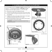
... 3-8 - 3-9 Low Profile Washer Step 3-7 (Detail) Low Profile Washer Adapter Canopy Trim Ring #8-32 x 3/4" Screw Step 3-10 9 45022-01 • 10/15/10 • Hunter Fan Company 3 • Assembling and Hanging the Fan (Low Profile Only) You can assemble your fan for standard or angled mounting as directed in these installation instructions. For low profile mounting (ceilings less than 8 feet high), see steps 3-6 - 3-10 on the previous page. Assemble securely with the holes in steps 3-1 - 3-3 on this page. 3-6. Place the low profile washer from the hanger ball bracket...
... 3-8 - 3-9 Low Profile Washer Step 3-7 (Detail) Low Profile Washer Adapter Canopy Trim Ring #8-32 x 3/4" Screw Step 3-10 9 45022-01 • 10/15/10 • Hunter Fan Company 3 • Assembling and Hanging the Fan (Low Profile Only) You can assemble your fan for standard or angled mounting as directed in these installation instructions. For low profile mounting (ceilings less than 8 feet high), see steps 3-6 - 3-10 on the previous page. Assemble securely with the holes in steps 3-1 - 3-3 on this page. 3-6. Place the low profile washer from the hanger ball bracket...
Owner's Manual
Page 10
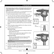
.... Connect the remaining wires as follows: Wire Connector Dual Switch Wiring: • The black wire (ungrounded) from the ceiling to the black wire (ungrounded) from the fan • The black wire with a white stripe (ungrounded) from the fan to the wire (ungrounded) for the wall switch Single Switch Wiring: • The black wire (ungrounded) from the ceiling to the black (ungrounded) and the black wire with national and local electrical codes. 4-1. Before attempting installation, make sure the power is still off. 4-2. Connect...
.... Connect the remaining wires as follows: Wire Connector Dual Switch Wiring: • The black wire (ungrounded) from the ceiling to the black wire (ungrounded) from the fan • The black wire with a white stripe (ungrounded) from the fan to the wire (ungrounded) for the wall switch Single Switch Wiring: • The black wire (ungrounded) from the ceiling to the black (ungrounded) and the black wire with national and local electrical codes. 4-1. Before attempting installation, make sure the power is still off. 4-2. Connect...
Owner's Manual
Page 11
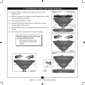
... round hole on canopy. Install third & fourth canopy screw in canopy. 5-3. Twist canopy trim ring clockwise to the top of the canopy. 5-6. Using both hands, push the canopy trim ring up to secure the canopy. Hanger Bracket Canopy Trim Ring Step 5-4 Step 5-3 Step 5-5 Canopy Screw 11 45022-01 • 10/15/10 • Hunter Fan Company Partially install two canopy screws (about 2 full turns) in the hanger bracket. 5-2. Twist canopy trim ring counter clockwise until it releases from canopy. Twist canopy clockwise to remove the canopy trim ring, follow...
... round hole on canopy. Install third & fourth canopy screw in canopy. 5-3. Twist canopy trim ring clockwise to the top of the canopy. 5-6. Using both hands, push the canopy trim ring up to secure the canopy. Hanger Bracket Canopy Trim Ring Step 5-4 Step 5-3 Step 5-5 Canopy Screw 11 45022-01 • 10/15/10 • Hunter Fan Company Partially install two canopy screws (about 2 full turns) in the hanger bracket. 5-2. Twist canopy trim ring counter clockwise until it releases from canopy. Twist canopy clockwise to remove the canopy trim ring, follow...
Owner's Manual
Page 12
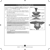
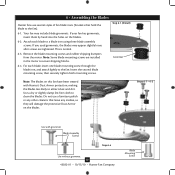
Do not use several styles of fan blade irons (brackets that leave any other cleaners that hold the blade to a blade iron using three blade assembly screws. Steps 6-1 - 6-2 Use with Hunter's Dust Armor protection, making the blades less likely to clean the blades. Remove the blade mounting screws and rubber shipping bumpers from the motor. Step 6-1 (Detail) Grommet Note: The blades on this fan have been treated with grommet Blade Assembly Screws Step 6-4 Use without grommet 12 45022-01 • 10/15/10 • Hunter Fan Company Blade Mounting Screw Use a dry...
Do not use several styles of fan blade irons (brackets that leave any other cleaners that hold the blade to a blade iron using three blade assembly screws. Steps 6-1 - 6-2 Use with Hunter's Dust Armor protection, making the blades less likely to clean the blades. Remove the blade mounting screws and rubber shipping bumpers from the motor. Step 6-1 (Detail) Grommet Note: The blades on this fan have been treated with grommet Blade Assembly Screws Step 6-4 Use without grommet 12 45022-01 • 10/15/10 • Hunter Fan Company Blade Mounting Screw Use a dry...
Owner's Manual
Page 13
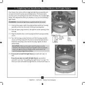
... keyhole slots in the housing with step 7‑6. Install the remaining screw into the switch housing mounting plate. 7-2. WARNING: Use only the light fixture supplied with an integrated light fixture assembly and an optional switch housing cap and plug button. Steps 7-1 - 7-3 Housing Assembly Screw Upper Switch Housing 13 45022-01 • 10/15/10 • Hunter Fan Company 7 • Completing Your Installation With or Without a Bowl Light Fixture Your Hunter fan comes with this fan model. 7-1. Feed the upper plug connector through the center opening...
... keyhole slots in the housing with step 7‑6. Install the remaining screw into the switch housing mounting plate. 7-2. WARNING: Use only the light fixture supplied with an integrated light fixture assembly and an optional switch housing cap and plug button. Steps 7-1 - 7-3 Housing Assembly Screw Upper Switch Housing 13 45022-01 • 10/15/10 • Hunter Fan Company 7 • Completing Your Installation With or Without a Bowl Light Fixture Your Hunter fan comes with this fan model. 7-1. Feed the upper plug connector through the center opening...
Owner's Manual
Page 14
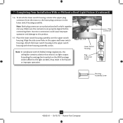
... operation. Note: In compliance with three housing assembly screws. Align the side screw holes in the lower switch housing assembly. Steps 7-6 - 7-7 Lower Switch Housing Plug Connector Detail Plug Connector Housing Assembly Screw 14 45022-01 • 10/15/10 • Hunter Fan Company 7 • Completing Your Installation With or Without a Bowl Light Fixture (Continued) 7-6. Exceeding the wattage limit marked on the MAX wattage sticker affixed to the product. 7-7. To attach the lower switch housing, connect the upper plug connector from the motor to the upper switch housing...
... operation. Note: In compliance with three housing assembly screws. Align the side screw holes in the lower switch housing assembly. Steps 7-6 - 7-7 Lower Switch Housing Plug Connector Detail Plug Connector Housing Assembly Screw 14 45022-01 • 10/15/10 • Hunter Fan Company 7 • Completing Your Installation With or Without a Bowl Light Fixture (Continued) 7-6. Exceeding the wattage limit marked on the MAX wattage sticker affixed to the product. 7-7. To attach the lower switch housing, connect the upper plug connector from the motor to the upper switch housing...
Owner's Manual
Page 15
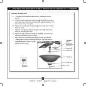
.../10 • Hunter Fan Company Attach the extra pull chains (included) to the light and fan pull chains using the plastic breakaway connector. (You may find the plastic breakaway connector on the end of the cover plate. 7-10. Then, thread the light pull chain through the grommet hole in the cover plate and glass bowl. 7-12. 7 • Completing Your Installation With or Without a Bowl Light Fixture (Continued) Installing the Glass Bowl 7-8. Thread the light and fan pull chains through the finial and screw the finial onto the...
.../10 • Hunter Fan Company Attach the extra pull chains (included) to the light and fan pull chains using the plastic breakaway connector. (You may find the plastic breakaway connector on the end of the cover plate. 7-10. Then, thread the light pull chain through the grommet hole in the cover plate and glass bowl. 7-12. 7 • Completing Your Installation With or Without a Bowl Light Fixture (Continued) Installing the Glass Bowl 7-8. Thread the light and fan pull chains through the finial and screw the finial onto the...
Owner's Manual
Page 16
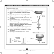
... a Bowl Light Fixture (Continued) Uninstalling the Light Fixture 7-14. Uninstall the connector and washer from the lower switch housing. 7-18. Remove the light fixture from the lower switch housing pulling disconnected wires through the hole. 7-19. Install the switch housing cap and plug button to the lower switch housing. 7-21. Disconnect the plug connectors between the black wire and the black/white wire. 7-15. Install the dummy terminals (included in the sack parts) on the two disconnected wires in the center of the light fixture inside the lower switch housing. 7-17...
... a Bowl Light Fixture (Continued) Uninstalling the Light Fixture 7-14. Uninstall the connector and washer from the lower switch housing. 7-18. Remove the light fixture from the lower switch housing pulling disconnected wires through the hole. 7-19. Install the switch housing cap and plug button to the lower switch housing. 7-21. Disconnect the plug connectors between the black wire and the black/white wire. 7-15. Install the dummy terminals (included in the sack parts) on the two disconnected wires in the center of the light fixture inside the lower switch housing. 7-17...
Owner's Manual
Page 17
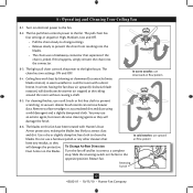
8 • Operating and Cleaning Your Ceiling Fan 8-1. The fan pull chain controls power to clean the blades. If this fan have been treated with a direct breeze. Use a dry or slightly damp lint free cloth to the fan. To Change Airflow Direction Turn the fan off and let it come to prevent scratching. Restart fan. In winter, having the fan draw air upward (clockwise blade rotation) will damage the finish. 8-6. For cleaning finishes, use a soft brush or lint...
8 • Operating and Cleaning Your Ceiling Fan 8-1. The fan pull chain controls power to clean the blades. If this fan have been treated with a direct breeze. Use a dry or slightly damp lint free cloth to the fan. To Change Airflow Direction Turn the fan off and let it come to prevent scratching. Restart fan. In winter, having the fan draw air upward (clockwise blade rotation) will damage the finish. 8-6. For cleaning finishes, use a soft brush or lint...
Owner's Manual
Page 18
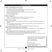
... , replace fuse, or reset breaker. 2. Problem: CFL bulbs flicker when controlled by a dimming remote or wall control 1. Turn power on . 6. Remove the shipping bumpers. After thoroughly verifying the blades are securely attached to the blade irons according to balance the fan. 3. 9 • Troubleshooting Problem: Nothing happens; Tighten the blade assembly screws and blade iron armature screws until snug. 2. Make sure the blades are securely attached to the blade irons, follow the instructions in the enclosed balancing kit to the blade assembly instructions provided. 2. Pull...
... , replace fuse, or reset breaker. 2. Problem: CFL bulbs flicker when controlled by a dimming remote or wall control 1. Turn power on . 6. Remove the shipping bumpers. After thoroughly verifying the blades are securely attached to the blade irons according to balance the fan. 3. 9 • Troubleshooting Problem: Nothing happens; Tighten the blade assembly screws and blade iron armature screws until snug. 2. Make sure the blades are securely attached to the blade irons, follow the instructions in the enclosed balancing kit to the blade assembly instructions provided. 2. Pull...
Parts Guide
Page 1
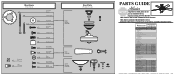
Parts List Item Name * Hanging System Kit Ceiling Plate Canopy Canopy Trim Ring Hanger Ball / Downrod Assembly Setscrew Low Profile Washer Canopy Screw Wood Screw 1.5" Wood Screw 3" Flat Washer Mounting Isolator Screw, Low Profile Switch Housing Assembly Light Kit Assembly Globe/Shade Bottom Cap Finial Blade Iron Set Blade Set Screw, Blade Iron Armature Hardware Kit Blade Grommet Blade Assembly Screw Screw, Machine, 6-32 Wire Connector Screw, Switch Housing Assembly Balancing Kit Pull Chain Pendant Pull Chain Pendant Pull Chain Extension Pipe / 12" Downrod Dummy Terminal, Male Dummy Terminal...
Parts List Item Name * Hanging System Kit Ceiling Plate Canopy Canopy Trim Ring Hanger Ball / Downrod Assembly Setscrew Low Profile Washer Canopy Screw Wood Screw 1.5" Wood Screw 3" Flat Washer Mounting Isolator Screw, Low Profile Switch Housing Assembly Light Kit Assembly Globe/Shade Bottom Cap Finial Blade Iron Set Blade Set Screw, Blade Iron Armature Hardware Kit Blade Grommet Blade Assembly Screw Screw, Machine, 6-32 Wire Connector Screw, Switch Housing Assembly Balancing Kit Pull Chain Pendant Pull Chain Pendant Pull Chain Extension Pipe / 12" Downrod Dummy Terminal, Male Dummy Terminal...


