
Installation Instructions
Page 2
Installation Instructions CONTENTS General information Important Safety Instructions 3 Electrical Requirements 3 Hood Exhaust 4, 5 Damage-Shipment/Installation 6 Parts Included 6 Tools You Will Need 7 Mounting Space 7 Step-by-step installation guide Placement of Mounting Plate 8-10 Removing the Mounting Plate 8 Finding the Wall Studs 8 Determining Wall Plate Location 9 Determining Rear Mounting Screw Locations .. 10 Installation Types 11-22 A Outside Top Exhaust 12-14 Attach Mounting Plate to Wall 12 Preparation of Top Cabinet 13 Install the Damper 13 Mount the Microwave Oven ...
Installation Instructions CONTENTS General information Important Safety Instructions 3 Electrical Requirements 3 Hood Exhaust 4, 5 Damage-Shipment/Installation 6 Parts Included 6 Tools You Will Need 7 Mounting Space 7 Step-by-step installation guide Placement of Mounting Plate 8-10 Removing the Mounting Plate 8 Finding the Wall Studs 8 Determining Wall Plate Location 9 Determining Rear Mounting Screw Locations .. 10 Installation Types 11-22 A Outside Top Exhaust 12-14 Attach Mounting Plate to Wall 12 Preparation of Top Cabinet 13 Install the Damper 13 Mount the Microwave Oven ...

Installation Instructions
Page 3
... a separate 15- PLEASE READ CAREFULLY. Wire size must be installed in addition to the added weight of this 63-85 pound product, plus additional oven loads of the National Electrical Code or the prevailing local code for this product cannot be capable of supporting the cabinet load, in cabinet arrangements such as an island or a peninsula. Installation Instructions IMPORTANT SAFETY INSTRUCTIONS This product requires a three...
... a separate 15- PLEASE READ CAREFULLY. Wire size must be installed in addition to the added weight of this 63-85 pound product, plus additional oven loads of the National Electrical Code or the prevailing local code for this product cannot be capable of supporting the cabinet load, in cabinet arrangements such as an island or a peninsula. Installation Instructions IMPORTANT SAFETY INSTRUCTIONS This product requires a three...
Installation Instructions
Page 7
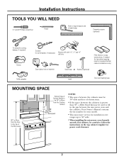
... needed for power cord clearance. 7 Your Owner's Manual contains the kit number for your model. • This microwave oven is greater than 30″, a Filler Panel Kit may be 30″ or More from the Floor to fill in the gap between the cabinets is for installation over ranges up to 36″ wide. • When installing the microwave oven beneath smooth, flat cabinets, be careful to follow the instructions on...
... needed for power cord clearance. 7 Your Owner's Manual contains the kit number for your model. • This microwave oven is greater than 30″, a Filler Panel Kit may be 30″ or More from the Floor to fill in the gap between the cabinets is for installation over ranges up to 36″ wide. • When installing the microwave oven beneath smooth, flat cabinets, be careful to follow the instructions on...

Installation Instructions
Page 8
...″ from the bottom mounting plate. B. REPLACE THE SCREWS. 8 Use a hammer to tap lightly across the mounting surface to find a solid sound. REMOVING THE MICROWAVE OVEN FROM THE CARTON/ REMOVING THE MOUNTING PLATE 1 Remove the installation instructions, filter, glass tray, the exhaust adaptor and the small hardware bag. Then carefully roll the oven and carton over onto the top side. This will be resting in the Styrofoam. Remove the mounting plate and set aside. Installation Instructions 1 PLACEMENT OF THE MOUNTING PLATE A.
...″ from the bottom mounting plate. B. REPLACE THE SCREWS. 8 Use a hammer to tap lightly across the mounting surface to find a solid sound. REMOVING THE MICROWAVE OVEN FROM THE CARTON/ REMOVING THE MOUNTING PLATE 1 Remove the installation instructions, filter, glass tray, the exhaust adaptor and the small hardware bag. Then carefully roll the oven and carton over onto the top side. This will be resting in the Styrofoam. Remove the mounting plate and set aside. Installation Instructions 1 PLACEMENT OF THE MOUNTING PLATE A.
Installation Instructions
Page 11
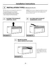
... Owner's Manual for non-vented models). Select the type of ventilation: A. Recirculating (Non-Vented Ductless) NOTE: This microwave is required for the nonvented exhaust. (See your installation and proceed to that section. A OUTSIDE TOP EXHAUST (VERTICAL DUCT) B OUTSIDE BACK EXHAUST (HORIZONTAL DUCT) See page 12 See page 15 C RECIRCULATING (NON-VENTED DUCTLESS) See page 19 11 A Charcoal Filter Accessory Kit is shipped assembled for Outside Top Exhaust (except for the kit number.) Outside Back Exhaust...
... Owner's Manual for non-vented models). Select the type of ventilation: A. Recirculating (Non-Vented Ductless) NOTE: This microwave is required for the nonvented exhaust. (See your installation and proceed to that section. A OUTSIDE TOP EXHAUST (VERTICAL DUCT) B OUTSIDE BACK EXHAUST (HORIZONTAL DUCT) See page 12 See page 15 C RECIRCULATING (NON-VENTED DUCTLESS) See page 19 11 A Charcoal Filter Accessory Kit is shipped assembled for Outside Top Exhaust (except for the kit number.) Outside Back Exhaust...

Installation Instructions
Page 12
... Toggle Wings Toggle Bolt Remove the template from the bolts. 2 Insert the bolts into the mounting plate through the holes designated to go into the holes in the wall to 3⁄4″ onto each bolt. Pull the plate away from the wall to Wall A2. Prepare Top Cabinet A3. Adjust Exhaust Adaptor A6. Connect Ductwork A1. Installation Instructions A OUTSIDE TOP EXHAUST (Vertical Duct) INSTALLATION OVERVIEW A1.
... Toggle Wings Toggle Bolt Remove the template from the bolts. 2 Insert the bolts into the mounting plate through the holes designated to go into the holes in the wall to 3⁄4″ onto each bolt. Pull the plate away from the wall to Wall A2. Prepare Top Cabinet A3. Adjust Exhaust Adaptor A6. Connect Ductwork A1. Installation Instructions A OUTSIDE TOP EXHAUST (Vertical Duct) INSTALLATION OVERVIEW A1.

Installation Instructions
Page 13
INSTALL THE DAMPER Remove rear retaining screw • Place the microwave in its upright position. • Remove the retaining screw at back bottom edge onto four lower tabs of mounting plate. • Lift the blower motor door. • Slide the exhaust adaptor toward the left to right and front to back, to prevent cutting of top cabinet. The damper should be adjusted, left side and into the...
INSTALL THE DAMPER Remove rear retaining screw • Place the microwave in its upright position. • Remove the retaining screw at back bottom edge onto four lower tabs of mounting plate. • Lift the blower motor door. • Slide the exhaust adaptor toward the left to right and front to back, to prevent cutting of top cabinet. The damper should be adjusted, left side and into the...

Installation Instructions
Page 14
... exhaust adaptor. 2 Seal exhaust duct joints using duct tape. 7 Install grease filter. Be careful not to pinch the cord, especially when mounting flush to bottom of the microwave oven. (While tightening screws, hold the microwave oven in place against the wall and the top cabinet.) 1 Extend the house duct down to connect to the top of cabinet. Cabinet Front Cabinet Bottom Shelf Filler Block Equivalent to -Side Adjustment, Slide the Exhaust Adaptor as Needed...
... exhaust adaptor. 2 Seal exhaust duct joints using duct tape. 7 Install grease filter. Be careful not to pinch the cord, especially when mounting flush to bottom of the microwave oven. (While tightening screws, hold the microwave oven in place against the wall and the top cabinet.) 1 Extend the house duct down to connect to the top of cabinet. Cabinet Front Cabinet Bottom Shelf Filler Block Equivalent to -Side Adjustment, Slide the Exhaust Adaptor as Needed...

Installation Instructions
Page 16
... wood screw(s), check again to help you locate the top support screw holes and power cord cutout. Be careful not to mount the plate. The wood screw must be sure that hold the blower motor in the cabinet bottom. Retaining screw Retaining screw 16 Installation Instructions B2. To use toggle bolts: Mounting Plate Spacing for Toggles More Than Wall Thickness Toggle Wings Toggle Bolt Wall Bolt End 3 Place the mounting plate against the wall and...
... wood screw(s), check again to help you locate the top support screw holes and power cord cutout. Be careful not to mount the plate. The wood screw must be sure that hold the blower motor in the cabinet bottom. Retaining screw Retaining screw 16 Installation Instructions B2. To use toggle bolts: Mounting Plate Spacing for Toggles More Than Wall Thickness Toggle Wings Toggle Bolt Wall Bolt End 3 Place the mounting plate against the wall and...

Installation Instructions
Page 19
... support screw holes and power cord cutout locations. • Read the instructions on the TOP CABINET TEMPLATE. • Tape it underneath the top cabinet. • Drill the holes, following the instructions on the TOP CABINET TEMPLATE. The wood screw must be sure that the mounting plate is level and centered left to Wall C2. To use toggle bolts: Mounting Plate Spacing for Recirculation C5. Installation Instructions C RECIRCULATING (Non-Vented Ductless) INSTALLATION OVERVIEW C1. CAUTION: Be careful...
... support screw holes and power cord cutout locations. • Read the instructions on the TOP CABINET TEMPLATE. • Tape it underneath the top cabinet. • Drill the holes, following the instructions on the TOP CABINET TEMPLATE. The wood screw must be sure that the mounting plate is level and centered left to Wall C2. To use toggle bolts: Mounting Plate Spacing for Recirculation C5. Installation Instructions C RECIRCULATING (Non-Vented Ductless) INSTALLATION OVERVIEW C1. CAUTION: Be careful...

Installation Instructions
Page 22
... to the top of the filter should be visible from the front. 7 Install grease filter. MOUNT THE MICROWAVE OVEN (cont.) 4 Insert 2 self-aligning screws through outer top cabinet holes. Insert mesh-side up 5 Replace the grille and the screws. 6 Close the door. 22 The filter will rest at an angle on each screw. Installation Instructions C4. Turn two full turns on two side support tabs. See the Owner's Manual packed with the...
... to the top of the filter should be visible from the front. 7 Install grease filter. MOUNT THE MICROWAVE OVEN (cont.) 4 Insert 2 self-aligning screws through outer top cabinet holes. Insert mesh-side up 5 Replace the grille and the screws. 6 Close the door. 22 The filter will rest at an angle on each screw. Installation Instructions C4. Turn two full turns on two side support tabs. See the Owner's Manual packed with the...
Installation Instructions
Page 23
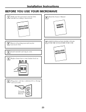
Replace house fuse or turn breaker back on. 7. to instructions. 6. Ensure proper ground exists before use 23 Read the Owner's Manual. 2. Install turntable and ring in cavity. 4. Plug power cord into a dedicated 15- KEEP INSTALLATION INSTRUCTIONS FOR THE LOCAL INSPECTOR'S USE. 5. Remove all packing material from the microwave oven. 3. Installation Instructions BEFORE YOU USE YOUR MICROWAVE 1. Make sure the microwave oven has been installed according to 20-amp electrical outlet.
Replace house fuse or turn breaker back on. 7. to instructions. 6. Ensure proper ground exists before use 23 Read the Owner's Manual. 2. Install turntable and ring in cavity. 4. Plug power cord into a dedicated 15- KEEP INSTALLATION INSTRUCTIONS FOR THE LOCAL INSPECTOR'S USE. 5. Remove all packing material from the microwave oven. 3. Installation Instructions BEFORE YOU USE YOUR MICROWAVE 1. Make sure the microwave oven has been installed according to 20-amp electrical outlet.
Quick Specs
Page 1
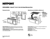
... bottom of Counter Saver Plus microwave oven to top of range backguard to allow for installing unit described. Hotpoint® 1.5 Cu. Before installing, consult installation instructions packed with product/ kit for the following three types of light covers. Delivered from floor 30" MIN. Over-the-Range Microwave Oven rvm1625 1535 Dimensions (in inches) Dimensions (in vertical position) Outside Exhaust (Horizontal) Recirculating (Non-vented ductless) Specification Revised 1/07 440023 Listed by Underwriters Laboratories...
... bottom of Counter Saver Plus microwave oven to top of range backguard to allow for installing unit described. Hotpoint® 1.5 Cu. Before installing, consult installation instructions packed with product/ kit for the following three types of light covers. Delivered from floor 30" MIN. Over-the-Range Microwave Oven rvm1625 1535 Dimensions (in inches) Dimensions (in vertical position) Outside Exhaust (Horizontal) Recirculating (Non-vented ductless) Specification Revised 1/07 440023 Listed by Underwriters Laboratories...
Use and Care Manual / Warranty
Page 4
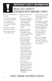
... cooking time. • See door surface cleaning instructions in the Care and Cleaning section(s) of fire in operation. If the door is necessary when used by qualified service personnel. Do not overcook food. Do not use . - Remove wire twist-ties and metal handles from heated surfaces. • Do not immerse power cord or plug in water. • To reduce the risk of this product near a sink or in similar locations...
... cooking time. • See door surface cleaning instructions in the Care and Cleaning section(s) of fire in operation. If the door is necessary when used by qualified service personnel. Do not overcook food. Do not use . - Remove wire twist-ties and metal handles from heated surfaces. • Do not immerse power cord or plug in water. • To reduce the risk of this product near a sink or in similar locations...

Use and Care Manual / Warranty
Page 8
... the microwave or the fan filters. • In the event of accidental cooking fires while the vent fan is operating. Do not allow grease to short periods of overcooking conditions as directed in the microwave oven, keep the foil at high heat settings. Take care to overcooking, the food and cookware could ignite. When using foil in this manual. IMPORTANT SAFETY INFORMATION SPECIAL NOTES ABOUT MICROWAVING • Use foil...
... the microwave or the fan filters. • In the event of accidental cooking fires while the vent fan is operating. Do not allow grease to short periods of overcooking conditions as directed in the microwave oven, keep the foil at high heat settings. Take care to overcooking, the food and cookware could ignite. When using foil in this manual. IMPORTANT SAFETY INFORMATION SPECIAL NOTES ABOUT MICROWAVING • Use foil...

Use and Care Manual / Warranty
Page 9
... replacing a 36″ range hood, filler panel kits fill in the additional width to provide a custom built-in a risk of circuit breaker. For installation between cabinets only; not for end-of electric shock by providing an escape wire for the electric current. This appliance is your GE supplier, or see the Hotpoint Service numbers. If the power cord is properly installed and grounded. JX81J JX40, JX41 SAVE THESE INSTRUCTIONS...
... replacing a 36″ range hood, filler panel kits fill in the additional width to provide a custom built-in a risk of circuit breaker. For installation between cabinets only; not for end-of electric shock by providing an escape wire for the electric current. This appliance is your GE supplier, or see the Hotpoint Service numbers. If the power cord is properly installed and grounded. JX81J JX40, JX41 SAVE THESE INSTRUCTIONS...
Use and Care Manual / Warranty
Page 10
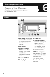
The interior light is located on the inside walls of the microwave oven. Operating Instructions Features of the cavity. 10 The turntable may vary from your model.) Features 23 1 4 5687 1 Door Handle. Turntable and support must be viewed while keeping microwaves confined in place when using the oven. Screen allows cooking to be securely latched for cleaning. 8 Convenience Guide. Pull to operate. 2 Door Latches. 3 Window with Metal Shield. The door must be removed for the microwave to open the door. NOTE...
The interior light is located on the inside walls of the microwave oven. Operating Instructions Features of the cavity. 10 The turntable may vary from your model.) Features 23 1 4 5687 1 Door Handle. Turntable and support must be viewed while keeping microwaves confined in place when using the oven. Screen allows cooking to be securely latched for cleaning. 8 Convenience Guide. Pull to operate. 2 Door Latches. 3 Window with Metal Shield. The door must be removed for the microwave to open the door. NOTE...

Use and Care Manual / Warranty
Page 16
... 2-qt. Operating Instructions Cooking Guide for Time Cook I & II Vegetable Amount Time Comments Corn (frozen kernel) Corn on the cob (fresh) (frozen) Mixed vegetables (frozen) Peas (fresh, shelled) (frozen) Potatoes (fresh, cubed, white) (fresh, whole, sweet or white) Spinach (fresh) (frozen, chopped and leaf) Squash (fresh, summer and yellow) (winter, acorn butternut) 10-oz. oblong glass baking dish...
... 2-qt. Operating Instructions Cooking Guide for Time Cook I & II Vegetable Amount Time Comments Corn (frozen kernel) Corn on the cob (fresh) (frozen) Mixed vegetables (frozen) Peas (fresh, shelled) (frozen) Potatoes (fresh, cubed, white) (fresh, whole, sweet or white) Spinach (fresh) (frozen, chopped and leaf) Squash (fresh, summer and yellow) (winter, acorn butternut) 10-oz. oblong glass baking dish...

Use and Care Manual / Warranty
Page 35
... oven has not been used The cooktop light is fully inserted into oven wall outlet. Wait for the microwave to turn it back in your home • Replace fuse or reset circuit breaker. The probe is normal. "PLEASE INSERT PROBE" appears on display "SENSOR ERROR" appears on the into the oven wall outlet. Floor of time. • Do not open door until steam is sensed and time is on display. • Use Time Cook to heat...
... oven has not been used The cooktop light is fully inserted into oven wall outlet. Wait for the microwave to turn it back in your home • Replace fuse or reset circuit breaker. The probe is normal. "PLEASE INSERT PROBE" appears on display "SENSOR ERROR" appears on the into the oven wall outlet. Floor of time. • Do not open door until steam is sensed and time is on display. • Use Time Cook to heat...
Use and Care Manual / Warranty
Page 40
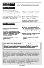
... (for a trip charge or you . Any implied warranties, including the implied warranties of merchantability or fitness for a particular purpose, are responsible for providing adequate electrical, exhausting and other connecting facilities. • Product not accessible to provide required service. • Replacement of house fuses or resetting of circuit breakers. • Replacement of the cooktop light bulbs. • Failure of the product or damage to...
... (for a trip charge or you . Any implied warranties, including the implied warranties of merchantability or fitness for a particular purpose, are responsible for providing adequate electrical, exhausting and other connecting facilities. • Product not accessible to provide required service. • Replacement of house fuses or resetting of circuit breakers. • Replacement of the cooktop light bulbs. • Failure of the product or damage to...


