Installation Instructions
Page 1
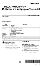
... tube, do not place your application. 3. Contact your local waste management authority for your old control in the trash. TB7100A1000 MultiPRO™ Multispeed and Multipurpose Thermostat APPLICATION INSTALLATION INSTRUCTIONS The TB7100A1000 MultiPRO™ Multispeed and Multipurpose Thermostat provides electronic control of 24 Vac heating and cooling systems. See Table 1 for automatic fan speed selection (fan coil...
... tube, do not place your application. 3. Contact your local waste management authority for your old control in the trash. TB7100A1000 MultiPRO™ Multispeed and Multipurpose Thermostat APPLICATION INSTALLATION INSTRUCTIONS The TB7100A1000 MultiPRO™ Multispeed and Multipurpose Thermostat provides electronic control of 24 Vac heating and cooling systems. See Table 1 for automatic fan speed selection (fan coil...
Installation Instructions
Page 2
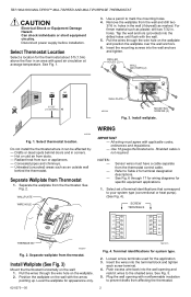
... wall anchors (provided) into the wall opening with the arrow pointing up. M22258 Fig. 1. Use 18 gauge thermostat wire. SCREW TERMINALS THERMOSTAT M22267 Fig. 2. Position the wallplate on the wall: 1. Loosen screw terminals used for specific equipment applications. 1....not required. Can shock individuals or short equipment circuitry. Use a pencil to prevent drafts from the thermostat. TB7100A1000 MULTIPRO™ MULTISPEED AND MULTIPURPOSE THERMOSTAT CAUTION Electrical Shock or Equipment Damage Hazard. See Fig. 6 through 17 for wiring diagrams for the...
... wall anchors (provided) into the wall opening with the arrow pointing up. M22258 Fig. 1. Use 18 gauge thermostat wire. SCREW TERMINALS THERMOSTAT M22267 Fig. 2. Position the wallplate on the wall: 1. Loosen screw terminals used for specific equipment applications. 1....not required. Can shock individuals or short equipment circuitry. Use a pencil to prevent drafts from the thermostat. TB7100A1000 MULTIPRO™ MULTISPEED AND MULTIPURPOSE THERMOSTAT CAUTION Electrical Shock or Equipment Damage Hazard. See Fig. 6 through 17 for wiring diagrams for the...
Installation Instructions
Page 3
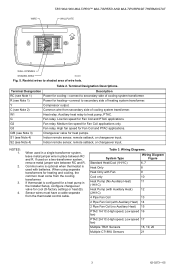
.... O/B (see Note 4) Indoor remote sensor, remote setback, or changeover input. Auxiliary heat relay to shaded area of cooling system transformer. G Fan relay. WIRE TB7100A1000 MULTIPRO™ MULTISPEED AND MULTIPURPOSE THERMOSTAT WALLPLATE WALL OPENING SHADED AREA M22266 Fig. 5. Restrict wires to heat pump, PTAC. Y Compressor output. S2 (see Note 3) Changeover valve for Fan Coil...
.... O/B (see Note 4) Indoor remote sensor, remote setback, or changeover input. Auxiliary heat relay to shaded area of cooling system transformer. G Fan relay. WIRE TB7100A1000 MULTIPRO™ MULTISPEED AND MULTIPURPOSE THERMOSTAT WALLPLATE WALL OPENING SHADED AREA M22266 Fig. 5. Restrict wires to heat pump, PTAC. Y Compressor output. S2 (see Note 3) Changeover valve for Fan Coil...
Installation Instructions
Page 4
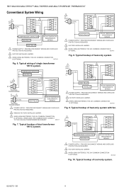
.../1C system. 1 L1 (HOT) C 3 W1 G G2 L2 24 VAC Y G3 O/B S1 RC S2 R2 HEAT RELAY INDOOR TEMPERATURE SENSOR/REMOTE SETBACK 1 POWER SUPPLY. TB7100A1000 MULTIPRO™ MULTISPEED AND MULTIPURPOSE THERMOSTAT Conventional System Wiring L1 1 (HOT) C 3 W1 G G2 Y G3 24 VAC O/B S1 L2 RC S2 R2 COMPRESSOR CONTACTOR FAN RELAY INDOOR TEMPERATURE SENSOR/REMOTE...
.../1C system. 1 L1 (HOT) C 3 W1 G G2 L2 24 VAC Y G3 O/B S1 RC S2 R2 HEAT RELAY INDOOR TEMPERATURE SENSOR/REMOTE SETBACK 1 POWER SUPPLY. TB7100A1000 MULTIPRO™ MULTISPEED AND MULTIPURPOSE THERMOSTAT Conventional System Wiring L1 1 (HOT) C 3 W1 G G2 Y G3 24 VAC O/B S1 L2 RC S2 R2 COMPRESSOR CONTACTOR FAN RELAY INDOOR TEMPERATURE SENSOR/REMOTE...
Installation Instructions
Page 5
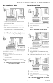
TB7100A1000 MULTIPRO™ MULTISPEED AND MULTIPURPOSE THERMOSTAT Heat Pump System Wiring Fan Coil System Wiring L1 (HOT) 3 24 VAC C W1 L2 G G2 1 Y G3 4 O/B S1 RC S2 R2 CHANGEOVER VALVE COMPRESSOR... FACTORY INSTALLED JUMPER. 3 WHEN USING BATTERIES, THE 24V COMMON CONNECTION IS OPTIONAL. WIRES MUST HAVE A CABLE SEPARATE FROM THE THERMOSTAT CABLE. M27421 Fig. 11. WIRES MUST HAVE A CABLE SEPARATE FROM THE THERMOSTAT CABLE. PROVIDE DISCONNECT MEANS AND OVERLOAD PROTECTION AS REQUIRED. 2 FACTORY INSTALLED JUMPER. 3 WHEN USING BATTERIES, THE 24V COMMON CONNECTION...
TB7100A1000 MULTIPRO™ MULTISPEED AND MULTIPURPOSE THERMOSTAT Heat Pump System Wiring Fan Coil System Wiring L1 (HOT) 3 24 VAC C W1 L2 G G2 1 Y G3 4 O/B S1 RC S2 R2 CHANGEOVER VALVE COMPRESSOR... FACTORY INSTALLED JUMPER. 3 WHEN USING BATTERIES, THE 24V COMMON CONNECTION IS OPTIONAL. WIRES MUST HAVE A CABLE SEPARATE FROM THE THERMOSTAT CABLE. M27421 Fig. 11. WIRES MUST HAVE A CABLE SEPARATE FROM THE THERMOSTAT CABLE. PROVIDE DISCONNECT MEANS AND OVERLOAD PROTECTION AS REQUIRED. 2 FACTORY INSTALLED JUMPER. 3 WHEN USING BATTERIES, THE 24V COMMON CONNECTION...
Installation Instructions
Page 6
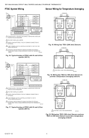
... IS A 10K OHM SENSOR. Typical hookup of PTAC with HI and LO fan speeds (1H/1C). WIRES MUST HAVE A CABLE SEPARATE FROM THE THERMOSTAT CABLE. Typical hookup of PTAC with HI and LO fan speeds (2H/1C). 1 TR21-A 1 TR21-A 1 THE TR21-A IS A 10K OHM ... network 62-0273-05 6 SUBBASE S1 S2 TR21 TR21 T T T T TR21 TR21 T T T T M27481 Fig. 18. M27483 Fig. 20. TB7100A1000 MULTIPRO™ MULTISPEED AND MULTIPURPOSE THERMOSTAT PTAC System Wiring Sensor Wiring for Temperature Averaging L1 (HOT) 3 24 VAC C W1 L2 G G2 1 Y G3 4 O/B S1 RC S2 R2 CHANGEOVER...
... IS A 10K OHM SENSOR. Typical hookup of PTAC with HI and LO fan speeds (1H/1C). WIRES MUST HAVE A CABLE SEPARATE FROM THE THERMOSTAT CABLE. Typical hookup of PTAC with HI and LO fan speeds (2H/1C). 1 TR21-A 1 TR21-A 1 THE TR21-A IS A 10K OHM ... network 62-0273-05 6 SUBBASE S1 S2 TR21 TR21 T T T T TR21 TR21 T T T T M27481 Fig. 18. M27483 Fig. 20. TB7100A1000 MULTIPRO™ MULTISPEED AND MULTIPURPOSE THERMOSTAT PTAC System Wiring Sensor Wiring for Temperature Averaging L1 (HOT) 3 24 VAC C W1 L2 G G2 1 Y G3 4 O/B S1 RC S2 R2 CHANGEOVER...
Installation Instructions
Page 7
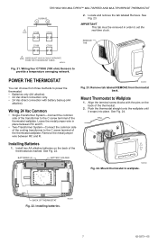
...-Connect the common side of the transformer to the C screw terminal of the thermostat. 2. See Fig. 22. BACK OF THERMOSTAT Fig. 22. Installing batteries. Install two AA alkaline batteries on the back of the thermostat wallplate. TB7100A1000 MULTIPRO™ MULTISPEED AND MULTIPURPOSE THERMOSTAT SUBBASE S1 S2 1 C7189 C7189 2. Leave the metal jumper wire in order to...
...-Connect the common side of the transformer to the C screw terminal of the thermostat. 2. See Fig. 22. BACK OF THERMOSTAT Fig. 22. Installing batteries. Install two AA alkaline batteries on the back of the thermostat wallplate. TB7100A1000 MULTIPRO™ MULTISPEED AND MULTIPURPOSE THERMOSTAT SUBBASE S1 S2 1 C7189 C7189 2. Leave the metal jumper wire in order to...
Installation Instructions
Page 8
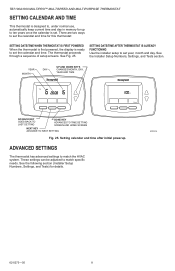
... SETTING SCREEN AND HOME SCREEN NEXT KEY ADVANCE TO NEXT SETTING Fig. 25. See Fig. 25. ADVANCED SETTINGS The thermostat has advanced settings to match specific needs. See the Installer Setup Numbers, Settings, and Tests section. There are two ...thermostat: SETTING DATE/TIME WHEN THERMOSTAT IS FIRST POWERED When the thermostat is first powered, the display is set. SETTING DATE/TIME AFTER THERMOSTAT IS ALREADY FUNCTIONING Use the installer setup to set year, month and day. TB7100A1000 MULTIPRO™ MULTISPEED AND MULTIPURPOSE THERMOSTAT SETTING CALENDAR AND TIME This thermostat...
... SETTING SCREEN AND HOME SCREEN NEXT KEY ADVANCE TO NEXT SETTING Fig. 25. See Fig. 25. ADVANCED SETTINGS The thermostat has advanced settings to match specific needs. See the Installer Setup Numbers, Settings, and Tests section. There are two ...thermostat: SETTING DATE/TIME WHEN THERMOSTAT IS FIRST POWERED When the thermostat is first powered, the display is set. SETTING DATE/TIME AFTER THERMOSTAT IS ALREADY FUNCTIONING Use the installer setup to set year, month and day. TB7100A1000 MULTIPRO™ MULTISPEED AND MULTIPURPOSE THERMOSTAT SETTING CALENDAR AND TIME This thermostat...
Installation Instructions
Page 9
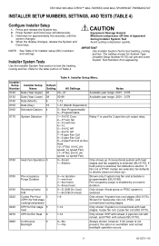
... shown if HP with reheat, 2 pipe fan coil with reheat, and PTAC with reheat (ISU 0170). 0280 Continuous Backlight 0 0-No 1-Yes Always shown; TB7100A1000 MULTIPRO™ MULTISPEED AND MULTIPURPOSE THERMOSTAT INSTALLER SETUP NUMBERS, SETTINGS, AND TESTS (TABLE 4) Configure Installer Setup 1. CAUTION Equipment Damage Hazard. If heat pump is bypassed during Installer System Test...
... shown if HP with reheat, 2 pipe fan coil with reheat, and PTAC with reheat (ISU 0170). 0280 Continuous Backlight 0 0-No 1-Yes Always shown; TB7100A1000 MULTIPRO™ MULTISPEED AND MULTIPURPOSE THERMOSTAT INSTALLER SETUP NUMBERS, SETTINGS, AND TESTS (TABLE 4) Configure Installer Setup 1. CAUTION Equipment Damage Hazard. If heat pump is bypassed during Installer System Test...
Installation Instructions
Page 10
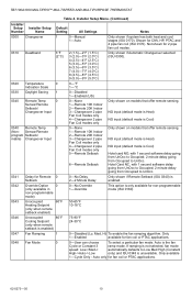
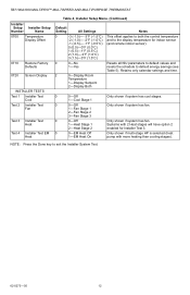
... Low Med High (Constant High->Auto-> Low only) and ISU 0348 is the fan Cycle or Constant 3 ramp mode. Only available 1-Cycle Only - TB7100A1000 MULTIPRO™ MULTISPEED AND MULTIPURPOSE THERMOSTAT Table 4. Not shown for non-programmable mode (ISU 0160) 0343 Unoccupied Heating Setpoint (only when remote setback enabled) 60°F 50-65°...
... Low Med High (Constant High->Auto-> Low only) and ISU 0348 is the fan Cycle or Constant 3 ramp mode. Only available 1-Cycle Only - TB7100A1000 MULTIPRO™ MULTISPEED AND MULTIPURPOSE THERMOSTAT Table 4. Not shown for non-programmable mode (ISU 0160) 0343 Unoccupied Heating Setpoint (only when remote setback enabled) 60°F 50-65°...
Installation Instructions
Page 11
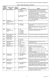
... in CNV, Heat Pump, PTAC (ISU 0170). Partial 1: Locks out schedule and system changes. Only shown if system has heat stages (ISU 0170). TB7100A1000 MULTIPRO™ MULTISPEED AND MULTIPURPOSE THERMOSTAT Table 4. Fan will be set after the user selects the constant fan speed. Applies to fossil or cool only systems (ISU 0170) Only...
... in CNV, Heat Pump, PTAC (ISU 0170). Partial 1: Locks out schedule and system changes. Only shown if system has heat stages (ISU 0170). TB7100A1000 MULTIPRO™ MULTISPEED AND MULTIPURPOSE THERMOSTAT Table 4. Fan will be set after the user selects the constant fan speed. Applies to fossil or cool only systems (ISU 0170) Only...
Installation Instructions
Page 12
... Setpoint 2-Display Both Notes This offset applies to both the control temperature and to exit the Installer System Test. 62-0273-05 12 TB7100A1000 MULTIPRO™ MULTISPEED AND MULTIPURPOSE THERMOSTAT Installer Setup Number Installer Setup Name 0700 Temperature Display Offset 0710 0720 Restore Factory Defaults Screen Display INSTALLER TESTS Test 1 Installer Test Cool...
... Setpoint 2-Display Both Notes This offset applies to both the control temperature and to exit the Installer System Test. 62-0273-05 12 TB7100A1000 MULTIPRO™ MULTISPEED AND MULTIPURPOSE THERMOSTAT Installer Setup Number Installer Setup Name 0700 Temperature Display Offset 0710 0720 Restore Factory Defaults Screen Display INSTALLER TESTS Test 1 Installer Test Cool...
Installation Instructions
Page 13
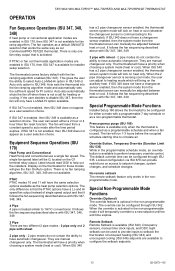
... fan sequencing described above with ISU 347, 348, 349. 2 pipe with a programmable 7 day schedule or as our CommercialPRO TB7220 thermostat. Remote Setback Remote Setback is not enabled, then ISU 349 does not appear as a user selection choice. The only difference is ...sensing cool mode, the user can be configured for fan ramp algorithm. The fan will have automatic changeover. OPERATION TB7100A1000 MULTIPRO™ MULTISPEED AND MULTIPURPOSE THERMOSTAT Fan Sequence Operations (ISU 347, 348, 349) If heat pump or conventional application modes are enabled in the...
... fan sequencing described above with ISU 347, 348, 349. 2 pipe with a programmable 7 day schedule or as our CommercialPRO TB7220 thermostat. Remote Setback Remote Setback is not enabled, then ISU 349 does not appear as a user selection choice. The only difference is ...sensing cool mode, the user can be configured for fan ramp algorithm. The fan will have automatic changeover. OPERATION TB7100A1000 MULTIPRO™ MULTISPEED AND MULTIPURPOSE THERMOSTAT Fan Sequence Operations (ISU 347, 348, 349) If heat pump or conventional application modes are enabled in the...
Installation Instructions
Page 14
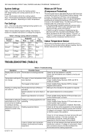
...Timer expires, "Cool On" or "Heat On" (heat pumps only)" appears solidly in the display). Heating or cooling does Thermostat minimum off . activated. If voltage is a call for more information. Check the heating equipment to find the cause of ... Sensor instructions for cooling or heating during the Minimum-Off Time, the thermostat displays "Wait." - were reached. Set system Selection to respond. TB7100A1000 MULTIPRO™ MULTISPEED AND MULTIPURPOSE THERMOSTAT System Settings Heat-Thermostat controls the heating system. Fan is on . Fan Settings Auto -Fan...
...Timer expires, "Cool On" or "Heat On" (heat pumps only)" appears solidly in the display). Heating or cooling does Thermostat minimum off . activated. If voltage is a call for more information. Check the heating equipment to find the cause of ... Sensor instructions for cooling or heating during the Minimum-Off Time, the thermostat displays "Wait." - were reached. Set system Selection to respond. TB7100A1000 MULTIPRO™ MULTISPEED AND MULTIPURPOSE THERMOSTAT System Settings Heat-Thermostat controls the heating system. Fan is on . Fan Settings Auto -Fan...
Installation Instructions
Page 15
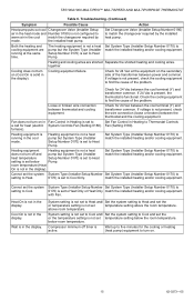
... (Installer Setup Number 0170) is not in Heating is not present, check the wire connection (loose or broken) between the thermostat and the cooling equipment. Loose or broken wire connection between power and common. match the installed heating and/or cooling equipment.... Number 0170) to Heat setting is not in the display). Cooling equipment failure. TB7100A1000 MULTIPRO™ MULTISPEED AND MULTIPURPOSE THERMOSTAT Table 6. the installed heat pump. If 24 Vac is present, the thermostat is set to find the cause of the problem. Heating equipment is not a heat...
... (Installer Setup Number 0170) is not in Heating is not present, check the wire connection (loose or broken) between the thermostat and the cooling equipment. Loose or broken wire connection between power and common. match the installed heating and/or cooling equipment.... Number 0170) to Heat setting is not in the display). Cooling equipment failure. TB7100A1000 MULTIPRO™ MULTISPEED AND MULTIPURPOSE THERMOSTAT Table 6. the installed heat pump. If 24 Vac is present, the thermostat is set to find the cause of the problem. Heating equipment is not a heat...
Installation Instructions
Page 16
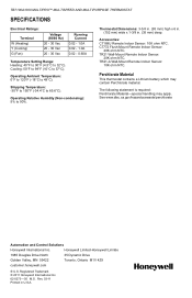
...Remote Indoor Sensor: 20K ohm NTC. Perchlorate Material This thermostat contains a Lithium battery which may apply. See www.dtsc.ca.gov/hazardouswaste/perchlorate Automation and Control Solutions Honeywell International Inc. Operating Relative Humidity (Non-condensing): 5% ...Honeywell International Inc. 62-0273-05 M.S. Operating Ambient Temperature: 0°F to 120°F (-18°C to 90%. Shipping Temperature: -30°F to 150°F (-34.4°C to 32°C). Rev. 03-11 Printed in . (35 mm) deep. TB7100A1000 MULTIPRO™ MULTISPEED AND MULTIPURPOSE THERMOSTAT...
...Remote Indoor Sensor: 20K ohm NTC. Perchlorate Material This thermostat contains a Lithium battery which may apply. See www.dtsc.ca.gov/hazardouswaste/perchlorate Automation and Control Solutions Honeywell International Inc. Operating Relative Humidity (Non-condensing): 5% ...Honeywell International Inc. 62-0273-05 M.S. Operating Ambient Temperature: 0°F to 120°F (-18°C to 90%. Shipping Temperature: -30°F to 150°F (-34.4°C to 32°C). Rev. 03-11 Printed in . (35 mm) deep. TB7100A1000 MULTIPRO™ MULTISPEED AND MULTIPURPOSE THERMOSTAT...