Owner's Manual
Page 2
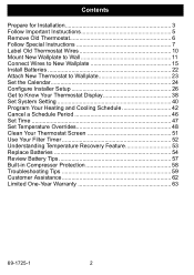
... Wallplate to Wall 11 Connect Wires to New Wallplate 15 Install Batteries 22 Attach New Thermostat to Wallplate 23 Set the Calendar 24 Configure Installer Setup 26 Get to Know Your Thermostat Display 38 Set System Setting 40 Program Your Heating and Cooling Schedule 42 Cancel a... Schedule Period 46 Set Time 47 Set Temperature Overrides 48 Clean Your Thermostat Screen 51 Use Your Filter Timer 52 Understanding Temperature Recovery Feature 53 Replace Batteries 54 Review Battery Tips 57 Built-in Compressor Protection 58 ...
... Wallplate to Wall 11 Connect Wires to New Wallplate 15 Install Batteries 22 Attach New Thermostat to Wallplate 23 Set the Calendar 24 Configure Installer Setup 26 Get to Know Your Thermostat Display 38 Set System Setting 40 Program Your Heating and Cooling Schedule 42 Cancel a... Schedule Period 46 Set Time 47 Set Temperature Overrides 48 Clean Your Thermostat Screen 51 Use Your Filter Timer 52 Understanding Temperature Recovery Feature 53 Replace Batteries 54 Review Battery Tips 57 Built-in Compressor Protection 58 ...

Owner's Manual
Page 4
use 7/32 in . Step 1. for plaster • Level (optional) • Hammer • Pencil • Electrical tape 69-1725-1 4 for drywall; Check that you have everything required for Installation (Cont) 2. use 3/16 in . Prepare for the installation: • Three AAA alkaline batteries • No. 2 Phillips screwdriver and standard pocket screwdriver • Drill • Drill bit -
use 7/32 in . Step 1. for plaster • Level (optional) • Hammer • Pencil • Electrical tape 69-1725-1 4 for drywall; Check that you have everything required for Installation (Cont) 2. use 3/16 in . Prepare for the installation: • Three AAA alkaline batteries • No. 2 Phillips screwdriver and standard pocket screwdriver • Drill • Drill bit -

Owner's Manual
Page 5
M22034 5 69-1725-1 DO NOT WIRE NEW THERMOSTAT BASED ON WIRE COLOR. Step 2. These Installation Instructions explain later how to use the enclosed wire labels to correctly mark the wires connected to the heating and/or cooling system. OLD THERMOSTAT YELLOW WHITE Y W RED G GREEN RC R ORANGE ! Follow Important Instructions 1. Do not connect the wires to the new thermostat based on wire color because damage can occur to your old thermostat.
M22034 5 69-1725-1 DO NOT WIRE NEW THERMOSTAT BASED ON WIRE COLOR. Step 2. These Installation Instructions explain later how to use the enclosed wire labels to correctly mark the wires connected to the heating and/or cooling system. OLD THERMOSTAT YELLOW WHITE Y W RED G GREEN RC R ORANGE ! Follow Important Instructions 1. Do not connect the wires to the new thermostat based on wire color because damage can occur to your old thermostat.

Owner's Manual
Page 10
Remove any remaining part of the wire. 69-1725-1 10 Do not allow the wires to wrap a wire label around each wire, use the enclosed wire labels to fall into the wall opening after the wires are disconnected. 2. As you disconnect each wire that matches the letter designation. ...Do not connect wires to the wire labels. OLD THERMOSTAT W Y RC G Y G RC W R R WIRE LABEL LETTER DESIGNATION SCREW TERMINAL WIRE WIRE HOLE M22039 When connecting the wires to the new...
Remove any remaining part of the wire. 69-1725-1 10 Do not allow the wires to wrap a wire label around each wire, use the enclosed wire labels to fall into the wall opening after the wires are disconnected. 2. As you disconnect each wire that matches the letter designation. ...Do not connect wires to the wire labels. OLD THERMOSTAT W Y RC G Y G RC W R R WIRE LABEL LETTER DESIGNATION SCREW TERMINAL WIRE WIRE HOLE M22039 When connecting the wires to the new...

Owner's Manual
Page 15
... system. If you have a CONVENTIONAL or HEAT PUMP system. 15 69-1725-1 See table on the wallplate. 2. Step 7. If wires are to wire the new thermostat. WALLPLATE METAL JUMPER WIRE TERMINAL BLOCK SCREW TERMINALS LETTER DESIGNATIONS RC R W Y G C M22206 3. Select the correct letter designations to New Wallplate 1. Match the labeled... wires to the letter designations on page 29 to help you determine if you have a standard heating and/or cooling system, use the HEAT PUMP letter designations to be connected, leave the metal jumper wire in place.
... system. If you have a CONVENTIONAL or HEAT PUMP system. 15 69-1725-1 See table on the wallplate. 2. Step 7. If wires are to wire the new thermostat. WALLPLATE METAL JUMPER WIRE TERMINAL BLOCK SCREW TERMINALS LETTER DESIGNATIONS RC R W Y G C M22206 3. Select the correct letter designations to New Wallplate 1. Match the labeled... wires to the letter designations on page 29 to help you determine if you have a standard heating and/or cooling system, use the HEAT PUMP letter designations to be connected, leave the metal jumper wire in place.

Owner's Manual
Page 16
Insert the labeled wires into the holes on the side of the labeled wires do not match the letter designations, see next page for wire connections. WALLPLATE WIRE HOLE INSERT WIRE IN HOLE YW RC R G LABELED WIRES TERMINAL BLOCK SCREW TERMINALS LETTER DESIGNATIONS RC R W Y G C (NOT USED) M22207 69-1725-1 16 Step 7. Connect Wires to New Wallplate (Cont) 5. Tighten the screw terminals. 6. If any of the terminal block that match the letter designations. Loosen the screw terminals.
Insert the labeled wires into the holes on the side of the labeled wires do not match the letter designations, see next page for wire connections. WALLPLATE WIRE HOLE INSERT WIRE IN HOLE YW RC R G LABELED WIRES TERMINAL BLOCK SCREW TERMINALS LETTER DESIGNATIONS RC R W Y G C (NOT USED) M22207 69-1725-1 16 Step 7. Connect Wires to New Wallplate (Cont) 5. Tighten the screw terminals. 6. If any of the terminal block that match the letter designations. Loosen the screw terminals.

Owner's Manual
Page 17
...appear on the new thermostat the labeled wires 1 RC 1 R RC or R R or RH, 4, V W or W1, H W Y or Y1, M Y G or F G C or C1, X, B C Y2 Y2 W2 W2 2 2 34 M22208 Do not connect more than one wire to each terminal. Be sure to New Wallplate (Cont) 7. Use the information on ...your old and new thermostats. Connect Wires to read the notes referenced in the numbered triangles above. CONVENTIONAL Possible letter letter designations designations on on ...
...appear on the new thermostat the labeled wires 1 RC 1 R RC or R R or RH, 4, V W or W1, H W Y or Y1, M Y G or F G C or C1, X, B C Y2 Y2 W2 W2 2 2 34 M22208 Do not connect more than one wire to each terminal. Be sure to New Wallplate (Cont) 7. Use the information on ...your old and new thermostats. Connect Wires to read the notes referenced in the numbered triangles above. CONVENTIONAL Possible letter letter designations designations on on ...

Owner's Manual
Page 18
... wire should be connected on the new thermostat. 2 If wires were connected to the new thermostat. Connect the old R to the new RC and the old RH to the new R. 3 If two C and/or C1 wires were connected to the old thermostat, do not use. 4 If one of each wire separately with electrical tape... and do not connect them to both RC and R on the new thermostat, remove metal jumper wire between RC and R on the new thermostat. Wrap the bare end of the terminals, RC...
... wire should be connected on the new thermostat. 2 If wires were connected to the new thermostat. Connect the old R to the new RC and the old RH to the new R. 3 If two C and/or C1 wires were connected to the old thermostat, do not use. 4 If one of each wire separately with electrical tape... and do not connect them to both RC and R on the new thermostat, remove metal jumper wire between RC and R on the new thermostat. Wrap the bare end of the terminals, RC...
Owner's Manual
Page 19
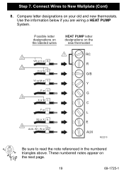
Possible letter designations on the labeled wires HEAT PUMP letter designations on the new thermostat 1 2 VR or V or R 3 H or B, O Y1 or M or Y F or G 3 X or B, C F or L X2 or X, E 4 AUX, W1, W or W2 RC R O/B Y G C L E AUX M22210 Be sure to New Wallplate (Cont) 8. Use the information below if you are wiring a HEAT PUMP System. These numbered notes appear on your old and new thermostats. Connect Wires to read the note referenced in the numbered triangles above. Step 7. Compare letter designations on the next page. 19 69-1725-1
Possible letter designations on the labeled wires HEAT PUMP letter designations on the new thermostat 1 2 VR or V or R 3 H or B, O Y1 or M or Y F or G 3 X or B, C F or L X2 or X, E 4 AUX, W1, W or W2 RC R O/B Y G C L E AUX M22210 Be sure to New Wallplate (Cont) 8. Use the information below if you are wiring a HEAT PUMP System. These numbered notes appear on your old and new thermostats. Connect Wires to read the note referenced in the numbered triangles above. Step 7. Compare letter designations on the next page. 19 69-1725-1
Owner's Manual
Page 24
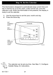
When the thermostat is first powered, the display is ready to set the calendar. 1. Use the arrow keys to set the year, month and day. 2. SET CURRENT DATE SET MONTH MON TUE WED THU FRI DONE USE ARROWS TO SET YEAR M22226 The calendar can be set . Step 10. Press the Done key. Set the Calendar This thermostat is set any time. See Step 11, Configure Installer Setup, for up to ten years, under normal use, once the calendar is designed to automatically keep current time and day in memory for instructions. 69-1725-1 24
When the thermostat is first powered, the display is ready to set the calendar. 1. Use the arrow keys to set the year, month and day. 2. SET CURRENT DATE SET MONTH MON TUE WED THU FRI DONE USE ARROWS TO SET YEAR M22226 The calendar can be set . Step 10. Press the Done key. Set the Calendar This thermostat is set any time. See Step 11, Configure Installer Setup, for up to ten years, under normal use, once the calendar is designed to automatically keep current time and day in memory for instructions. 69-1725-1 24

Owner's Manual
Page 25
Press the Done key. USE ARROWS TO SET TIME MON WED THU FRI SAT DONE M22227 25 69-1725-1 Use the arrow keys to set the current time. 4. Set the Calendar (Cont) 3. Step 10.
Press the Done key. USE ARROWS TO SET TIME MON WED THU FRI SAT DONE M22227 25 69-1725-1 Use the arrow keys to set the current time. 4. Set the Calendar (Cont) 3. Step 10.
Owner's Manual
Page 26
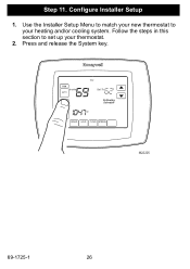
Configure Installer Setup 1. Press and release the System key. Step 11. FAN ON Inside AUTO THU Set To SYSTEM EM HEAT OFF COOL Following Schedule AM SCHED HOLD CLOCK SCREEN M22225 69-1725-1 26 Use the Installer Setup Menu to match your new thermostat to set up your heating and/or cooling system. Follow the steps in this section to your thermostat. 2.
Configure Installer Setup 1. Press and release the System key. Step 11. FAN ON Inside AUTO THU Set To SYSTEM EM HEAT OFF COOL Following Schedule AM SCHED HOLD CLOCK SCREEN M22225 69-1725-1 26 Use the Installer Setup Menu to match your new thermostat to set up your heating and/or cooling system. Follow the steps in this section to your thermostat. 2.

Owner's Manual
Page 31
... NUMBER DONE PRESS TO EXIT INSTALLER SETUP UP ARROW DOWN ARROW Installer Setup Number 0190 Installer Setup Name (Select Your Setting) Settings Heat Pump 0 - Changeover Use this setting if you do not have a number 0190 on the left side of your display, press the Up or Down arrow to the O/B terminal... Installer Setup Number. After you connected a Valve wire labeled O to select your setting, press the Up arrow key to go to the next page. 14. Use this setting if you select your setting for Installer Setup Number 0190. 15.
... NUMBER DONE PRESS TO EXIT INSTALLER SETUP UP ARROW DOWN ARROW Installer Setup Number 0190 Installer Setup Name (Select Your Setting) Settings Heat Pump 0 - Changeover Use this setting if you do not have a number 0190 on the left side of your display, press the Up or Down arrow to the O/B terminal... Installer Setup Number. After you connected a Valve wire labeled O to select your setting, press the Up arrow key to go to the next page. 14. Use this setting if you select your setting for Installer Setup Number 0190. 15.

Owner's Manual
Page 41
FAN AUTO Inside SYSTEM HEAT THU Set To Following Schedule AM SCHED HOLD CLOCK SCREEN M22262 41 69-1725-1 The fan runs only when the heating or cooling system is on. On-The fan runs continuously. Set System Setting (Cont) Set Fan Setting Press the Fan button to select Auto or On: Auto-Normal setting for more efficient air cleaning. Use this setting for improved air circulation or for most homes.
FAN AUTO Inside SYSTEM HEAT THU Set To Following Schedule AM SCHED HOLD CLOCK SCREEN M22262 41 69-1725-1 The fan runs only when the heating or cooling system is on. On-The fan runs continuously. Set System Setting (Cont) Set Fan Setting Press the Fan button to select Auto or On: Auto-Normal setting for more efficient air cleaning. Use this setting for improved air circulation or for most homes.
Owner's Manual
Page 47
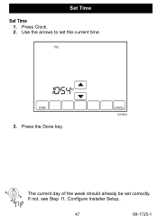
TUE AM DONE 3. Press the Done key. CANCEL M19958 The current day of the week should already be set the current time. If not, see Step 11, Configure Installer Setup. 47 69-1725-1 Use the arrows to set correctly. Press Clock. 2. Set Time Set Time 1.
TUE AM DONE 3. Press the Done key. CANCEL M19958 The current day of the week should already be set the current time. If not, see Step 11, Configure Installer Setup. 47 69-1725-1 Use the arrows to set correctly. Press Clock. 2. Set Time Set Time 1.

Owner's Manual
Page 51
Use a damp cloth slightly moistened with water or household glass cleaner to clean the thermostat screen. 51 69-1725-1 Do not spray any type of liquid directly onto the thermostat itself. Clean Your Thermostat Screen 1. Then use the cloth to clean the screen. 3. Press the Screen key. The thermostat locks out all touch keys for cleaning. Press the Done key to return to allow for 30 seconds to the Home Screen and normal operation. Repeat the above steps, as necessary. 4. OK TO CLEAN SCREEN M19964 2. If using household glass cleaner, spray the cleaner on a cloth.
Use a damp cloth slightly moistened with water or household glass cleaner to clean the thermostat screen. 51 69-1725-1 Do not spray any type of liquid directly onto the thermostat itself. Clean Your Thermostat Screen 1. Then use the cloth to clean the screen. 3. Press the Screen key. The thermostat locks out all touch keys for cleaning. Press the Done key to return to allow for 30 seconds to the Home Screen and normal operation. Repeat the above steps, as necessary. 4. OK TO CLEAN SCREEN M19964 2. If using household glass cleaner, spray the cleaner on a cloth.

Owner's Manual
Page 52
... TUE WED THU FRI SAT SUN FAN AUTO OK TO PICK MULTIPLE DAYS SCREEN LOCKED CHANGE FILTER UV LAMP HUMIDIFIER PAD Inside Set To SYSTEM RESET HEAT ...Installer Setup or the new reload value you when to change your furnace filter. Use the Up or Down arrow keys to change the number of run Time Days. Press the Done key to go back to restart the filter timer. Press...value. "Change Filter" appears on the screen. 2. Press the Reset key to viewing the filter timer. 4. Use Your Filter Timer The Filter Timer notifies you selected in step 2.) 5. Press the Done key. 69-1725-1 52
... TUE WED THU FRI SAT SUN FAN AUTO OK TO PICK MULTIPLE DAYS SCREEN LOCKED CHANGE FILTER UV LAMP HUMIDIFIER PAD Inside Set To SYSTEM RESET HEAT ...Installer Setup or the new reload value you when to change your furnace filter. Use the Up or Down arrow keys to change the number of run Time Days. Press the Done key to go back to restart the filter timer. Press...value. "Change Filter" appears on the screen. 2. Press the Reset key to viewing the filter timer. 4. Use Your Filter Timer The Filter Timer notifies you selected in step 2.) 5. Press the Done key. 69-1725-1 52
Owner's Manual
Page 57
...the display one month before the batteries run down completely. 57 69-1725-1 Always use fresh AAA alkaline batteries. Although the thermostat has a Low Battery indicator, replace the batteries once a year to prevent the thermostat and heating/ cooling system from shutting down if the batteries run down due to ... The LO Battery indicator flashes in the display. Review Battery Tips 1. Replace the batteries as soon as long and can leak, causing thermostat damage. 3. As a precaution, replace the batteries when leaving your home for more than a month to lack of battery power. 4.
...the display one month before the batteries run down completely. 57 69-1725-1 Always use fresh AAA alkaline batteries. Although the thermostat has a Low Battery indicator, replace the batteries once a year to prevent the thermostat and heating/ cooling system from shutting down if the batteries run down due to ... The LO Battery indicator flashes in the display. Review Battery Tips 1. Replace the batteries as soon as long and can leak, causing thermostat damage. 3. As a precaution, replace the batteries when leaving your home for more than a month to lack of battery power. 4.

Owner's Manual
Page 63
...from defects in the workmanship or materials, under normal use and service, for a period of one (1) year from the date of purchase by damage which occurred while the product was in the possession of a consumer. If you . HONEYWELL SHALL NOT BE LIABLE FOR ANY LOSS OR DAMAGE...Douglas Dr N Golden Valley, MN 55422 This warranty does not cover removal or reinstallation costs. In Canada, write Retail Products ON15-02H, Honeywell Limited/Honeywell Limitée, 35 Dynamic Drive, Scarborough, Ontario M1V4Z9. 63 69-1725-1 THE DURATION OF ANY IMPLIED WARRANTIES, INCLUDING THE WARRANTIES OF ...
...from defects in the workmanship or materials, under normal use and service, for a period of one (1) year from the date of purchase by damage which occurred while the product was in the possession of a consumer. If you . HONEYWELL SHALL NOT BE LIABLE FOR ANY LOSS OR DAMAGE...Douglas Dr N Golden Valley, MN 55422 This warranty does not cover removal or reinstallation costs. In Canada, write Retail Products ON15-02H, Honeywell Limited/Honeywell Limitée, 35 Dynamic Drive, Scarborough, Ontario M1V4Z9. 63 69-1725-1 THE DURATION OF ANY IMPLIED WARRANTIES, INCLUDING THE WARRANTIES OF ...


