
Owner's Manual
Page 21
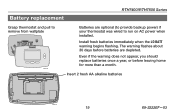
Even if the warning does not appear, you should replace batteries once a year, or before batteries are optional (to provide backup power) if your thermostat was wired to run on AC power when installed. Insert 2 fresh AA alkaline batteries M28101 19 69-2222EF-03 The warning flashes about 30 days before leaving home for more than a month. Battery replacement RTH7400/RTH7500 Series Grasp thermostat and pull to remove from wallplate M28103 Batteries are depleted. Install fresh batteries immediately when the LO BATT warning begins flashing.
Even if the warning does not appear, you should replace batteries once a year, or before batteries are optional (to provide backup power) if your thermostat was wired to run on AC power when installed. Insert 2 fresh AA alkaline batteries M28101 19 69-2222EF-03 The warning flashes about 30 days before leaving home for more than a month. Battery replacement RTH7400/RTH7500 Series Grasp thermostat and pull to remove from wallplate M28103 Batteries are depleted. Install fresh batteries immediately when the LO BATT warning begins flashing.

Owners Guide
Page 2
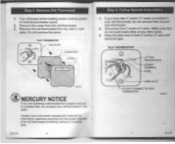
call Honeywell Customer Care at 1-800-468-1502 before returning the thermostat to Wallpiele Configure Installer Setup Customer Assistance Limited One-Year Warranty 64-1730 Step 1. Contents ... . Check that the following items are included 5 6 7 10 11 16 23 WALLPLATE 24 26 THERMOSTAT 62 63 MOUNTING SCREWS (2) AND WALL ANCHORS (2) -0TT OWNER'S GUIDE WIRE LABELS CAUTION CARD/ OWNER'S GUIDE itummegicon ••=t 004•0 Min YIP• .i• b If any of the items shown above are missing. Prepare for...
call Honeywell Customer Care at 1-800-468-1502 before returning the thermostat to Wallpiele Configure Installer Setup Customer Assistance Limited One-Year Warranty 64-1730 Step 1. Contents ... . Check that the following items are included 5 6 7 10 11 16 23 WALLPLATE 24 26 THERMOSTAT 62 63 MOUNTING SCREWS (2) AND WALL ANCHORS (2) -0TT OWNER'S GUIDE WIRE LABELS CAUTION CARD/ OWNER'S GUIDE itummegicon ••=t 004•0 Min YIP• .i• b If any of the items shown above are missing. Prepare for...

Owners Guide
Page 3
... not connect the wires to the new thermostat based on wire color because damage can occur to the heating and/or cooling system These Installation Instructions explain later how to use 7/32 in for drywall: use the enclosed wire labels to correctly mark the wires connected to your old... thermostat OLD THERMOSTAT TE DO NOT WIRE NEW THERMOSTAT BASED ON WIRE COLOR. 69-1730 Prepare for plaster • Level (optional) • Hammer •...
... not connect the wires to the new thermostat based on wire color because damage can occur to the heating and/or cooling system These Installation Instructions explain later how to use 7/32 in for drywall: use the enclosed wire labels to correctly mark the wires connected to your old... thermostat OLD THERMOSTAT TE DO NOT WIRE NEW THERMOSTAT BASED ON WIRE COLOR. 69-1730 Prepare for plaster • Level (optional) • Hammer •...
Owners Guide
Page 4
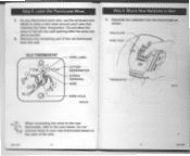
...thermostat in a sealed tube 69.17 30 6 Step 4. Disconnect the C and/or Cl wires Make sure they do not place your new thermostat 2. OLD THERMOSTAT 0 C \ R C LETTER DESIGNATION SCREW TERMINAL WIRE WIRE HOLE DO NOT CONNECT TO NEW THERMOSTAT M22201 7 es.173o Turn off power at the ...heating and/or cooling system or fuse/circuit breaker panel. 2. Do not remove the wires. Follow Special Instructions 1. Remove the cover from the wall or wall- plate. Remove Old Thermostat 1. If you are replacing a thermostat that ...
...thermostat in a sealed tube 69.17 30 6 Step 4. Disconnect the C and/or Cl wires Make sure they do not place your new thermostat 2. OLD THERMOSTAT 0 C \ R C LETTER DESIGNATION SCREW TERMINAL WIRE WIRE HOLE DO NOT CONNECT TO NEW THERMOSTAT M22201 7 es.173o Turn off power at the ...heating and/or cooling system or fuse/circuit breaker panel. 2. Do not remove the wires. Follow Special Instructions 1. Remove the cover from the wall or wall- plate. Remove Old Thermostat 1. If you are replacing a thermostat that ...

Owners Guide
Page 5
...Step 4. Follow Special Instructions (Cont) 5. Wrap the end of the wires that are not connected with electrical tape OLD THERMOSTAT Y r: Rc (0) LETTER DESIGNATION w SCREW TERMINAL WIRE WIRE HOLE WIRES NOT CONNECTED - If you find any wires not connected to your old thermostat. If you have only one C ... O C LETTER DESIGNATION SCREW TERMINAL WIRE R WIRE HOLE CONNECT TO THE "C" ON THE NEW THERMOSTAT M27223 Step 4. do not connect them to your old thermostat, connect this wire to C on the new thermostat Visit www honevwell com/yourhome or call Honeywell Customer Care at 1-800-468-1502...
...Step 4. Follow Special Instructions (Cont) 5. Wrap the end of the wires that are not connected with electrical tape OLD THERMOSTAT Y r: Rc (0) LETTER DESIGNATION w SCREW TERMINAL WIRE WIRE HOLE WIRES NOT CONNECTED - If you find any wires not connected to your old thermostat. If you have only one C ... O C LETTER DESIGNATION SCREW TERMINAL WIRE R WIRE HOLE CONNECT TO THE "C" ON THE NEW THERMOSTAT M27223 Step 4. do not connect them to your old thermostat, connect this wire to C on the new thermostat Visit www honevwell com/yourhome or call Honeywell Customer Care at 1-800-468-1502...
Owners Guide
Page 6
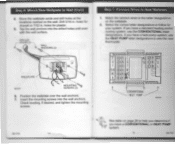
... Wallplate to the new thermostat. Label Old Thermostat Wires 1. Step 5. refer to fall into the wall opening after the wires are disconnected 2. Remove any remaining part of the wire 111.1730 t t ILI 130 use the enclosed wire labels to wrap a wire label around each wire. Do not connect wires to your new thermostat based on the color...
... Wallplate to the new thermostat. Label Old Thermostat Wires 1. Step 5. refer to fall into the wall opening after the wires are disconnected 2. Remove any remaining part of the wire 111.1730 t t ILI 130 use the enclosed wire labels to wrap a wire label around each wire. Do not connect wires to your new thermostat based on the color...
Owners Guide
Page 7
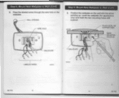
Mount New Wallplate to Wall (Cont) 3. WIRE HOLE Step 6. Position the wallplate on the wallplate WALL OPENING - Mount New Wallplate to Wall (Cont) 2. Pass the labeled wires through the wire hole on the wall with the arrow pointing up Level the wallplate (for appearance only) and mark the two mounting holes with a pencil. LEVEL PLACE LEVEL ON SUPPORT TABS MARX MOUNTING !C: HOLES (2) WALLPLATE LABELED WIRES 2ry WALLPLATE w2292 n-1730 12 13 Step 6.
Mount New Wallplate to Wall (Cont) 3. WIRE HOLE Step 6. Position the wallplate on the wallplate WALL OPENING - Mount New Wallplate to Wall (Cont) 2. Pass the labeled wires through the wire hole on the wall with the arrow pointing up Level the wallplate (for appearance only) and mark the two mounting holes with a pencil. LEVEL PLACE LEVEL ON SUPPORT TABS MARX MOUNTING !C: HOLES (2) WALLPLATE LABELED WIRES 2ry WALLPLATE w2292 n-1730 12 13 Step 6.
Owners Guide
Page 8
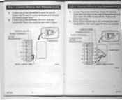
... New Wallplate to ,,,vENT140. HEAT PUMP 0 17110 /4 See table on page 29 to help you determine if you have a heat pump system. Connect Wires to follow for plaster 5. use the CONVENTIONAL letter designations If you have a standard heating and/or cooling system, use the HEAT PUMP letter designations to... at the locations marked on the wallplate. 2. If you have a CONVENTIONAL or HEAT PUMP I r system. 15 69-1730 Match the labeled wires to wire the new thermostat. Position the wallplate over the wall anchors. 7. Select the correct letter designations to New Wallplate 1.
... New Wallplate to ,,,vENT140. HEAT PUMP 0 17110 /4 See table on page 29 to help you determine if you have a heat pump system. Connect Wires to follow for plaster 5. use the CONVENTIONAL letter designations If you have a standard heating and/or cooling system, use the HEAT PUMP letter designations to... at the locations marked on the wallplate. 2. If you have a CONVENTIONAL or HEAT PUMP I r system. 15 69-1730 Match the labeled wires to wire the new thermostat. Position the wallplate over the wall anchors. 7. Select the correct letter designations to New Wallplate 1.
Owners Guide
Page 9
...side of the terminals. CONVENTIONAL LETTER DESIGNATIONS C WALLPLATE V w RC 14 R WIRE HOLE es. \- loosen the Rc and R screw terminals and remove the metal Jumper wire 4. see next page for wire connections, LABELED WIRES TERMINAL BLOCK SCREW TERMINALS - If only one of the terminal block that match.... 6. Rc or R. If any of the labeled wires do not match the letter designations. is to New Wallplate (Cont) 3. INSERT WIRE IN HOLE 88.1730 16 17 894730 If wires are to be connected, leave the metal jumper wire in place TERMINAL BLOCK SCREW TERMINALS LETTER DESIGNATIONS C up...
...side of the terminals. CONVENTIONAL LETTER DESIGNATIONS C WALLPLATE V w RC 14 R WIRE HOLE es. \- loosen the Rc and R screw terminals and remove the metal Jumper wire 4. see next page for wire connections, LABELED WIRES TERMINAL BLOCK SCREW TERMINALS - If only one of the terminal block that match.... 6. Rc or R. If any of the labeled wires do not match the letter designations. is to New Wallplate (Cont) 3. INSERT WIRE IN HOLE 88.1730 16 17 894730 If wires are to be connected, leave the metal jumper wire in place TERMINAL BLOCK SCREW TERMINALS LETTER DESIGNATIONS C up...

Owners Guide
Page 10
... (Cont) 7. Compare letter designations on the new thermoostat the latiebd wins T- 1 RC ® A-IR O W YO GO C C) 4. R64 44V, 4 2. am =bhp .. A If one C and/or Cl wire was connected to the old thermostat do not connect Mem lo the new thermostat wrap the bore end of the terminals. These numbered notes appear... on page 20 if you are wiring a CONVENTIONAL System Use the information on the next page 69.1730 19 69-1730 Use the information below if you are...
... (Cont) 7. Compare letter designations on the new thermoostat the latiebd wins T- 1 RC ® A-IR O W YO GO C C) 4. R64 44V, 4 2. am =bhp .. A If one C and/or Cl wire was connected to the old thermostat do not connect Mem lo the new thermostat wrap the bore end of the terminals. These numbered notes appear... on page 20 if you are wiring a CONVENTIONAL System Use the information on the next page 69.1730 19 69-1730 Use the information below if you are...

Owners Guide
Page 11
... both 0 and B. Compare letter designations on the next page. 89-1736 21 504730 If anoint wire is required. Connect Wires to New Wallplate (Cont) Step 7. some system modIkMion k rewired. contact Honeywell. ,L If the old themiostat had separate wires on WI, VI and W2, some system modMcallon is already matched to the C letter designation on...
... both 0 and B. Compare letter designations on the next page. 89-1736 21 504730 If anoint wire is required. Connect Wires to New Wallplate (Cont) Step 7. some system modIkMion k rewired. contact Honeywell. ,L If the old themiostat had separate wires on WI, VI and W2, some system modMcallon is already matched to the C letter designation on...

Owners Guide
Page 12
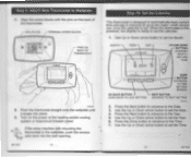
BATTERY HOLDER WALL OPENING SHADED AREA 64 1730 22 UP V72207 L I!1 BACK OF THERMOSTAT 2. Install Batteries 1. Install two fresh AA alkaline batteries on the back of the thermostat back. BATTERIES (2) - Connect Wires to New Wallplate (Cont) 9. Remove tab labeled 'Remove during installation' in the shaded area WIRE WALLPLATE Step 8. REMOVE TAB /- 23 641730 Step 7. Push excess wire back into the wall opening Keep wires in the lower right corner of the thermostat as marked on the thermostat.
BATTERY HOLDER WALL OPENING SHADED AREA 64 1730 22 UP V72207 L I!1 BACK OF THERMOSTAT 2. Install Batteries 1. Install two fresh AA alkaline batteries on the back of the thermostat back. BATTERIES (2) - Connect Wires to New Wallplate (Cont) 9. Remove tab labeled 'Remove during installation' in the shaded area WIRE WALLPLATE Step 8. REMOVE TAB /- 23 641730 Step 7. Push excess wire back into the wall opening Keep wires in the lower right corner of the thermostat as marked on the thermostat.
Owners Guide
Page 13
... to automatically keep current time and day in memory for up to Wallplate 1. once the calendar is ready to the wallplate, push the excess if wire back into place 3. Use the Up or Down arrow button to set the calendar. 1. Use the Up or Down arrow button to set the Date... to set the Year. 6. Push the thermostat straight onto the wallplate until it snaps into the wall opening 80-1730 zi Step 10. If the wires interfere with the pins on the power at the heating and/or cooling system or fuse/circuit breaker panel. When the thermostat is first powered...
... to automatically keep current time and day in memory for up to Wallplate 1. once the calendar is ready to the wallplate, push the excess if wire back into place 3. Use the Up or Down arrow button to set the calendar. 1. Use the Up or Down arrow button to set the Date... to set the Year. 6. Push the thermostat straight onto the wallplate until it snaps into the wall opening 80-1730 zi Step 10. If the wires interfere with the pins on the power at the heating and/or cooling system or fuse/circuit breaker panel. When the thermostat is first powered...

Owners Guide
Page 17
... (less than Cycle 90% efficient). If you conned's Valve ore labeled O to the OM lenninlil. 14:1310 ise-Ir3o 32 Step 11. After you connected a wire labeled B to the 013 terminal. Use thes setting if you select your setting for Installer Setup Number 0240 18. High-Efficiency Furnace. 1 • Gas or...
... (less than Cycle 90% efficient). If you conned's Valve ore labeled O to the OM lenninlil. 14:1310 ise-Ir3o 32 Step 11. After you connected a wire labeled B to the 013 terminal. Use thes setting if you select your setting for Installer Setup Number 0240 18. High-Efficiency Furnace. 1 • Gas or...
Owners Guide
Page 31
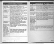
Heat puts out cool Pump Changeover Valve. See HeetingOforuCbios lgoar corner and the does not turn on A system monitor Is wired le the thenn09114 in Heating. make sure air in the heat 'the setting matches the changeover mode and required by the installed heat pump...in the display. guis set Check Installer Setup Number 0170, System setting Heating and/or Cooling System Type, make sure the bare portions of the wires are running at the same time Check Installer Setup Number 0170. Cannot set below the room temperature If 'Cool On' is active. Heating system ...
Heat puts out cool Pump Changeover Valve. See HeetingOforuCbios lgoar corner and the does not turn on A system monitor Is wired le the thenn09114 in Heating. make sure air in the heat 'the setting matches the changeover mode and required by the installed heat pump...in the display. guis set Check Installer Setup Number 0170, System setting Heating and/or Cooling System Type, make sure the bare portions of the wires are running at the same time Check Installer Setup Number 0170. Cannot set below the room temperature If 'Cool On' is active. Heating system ...


