
Owner's Manual
Page 1
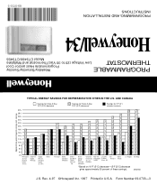
69-0733-3 PROGRAMMING AND INSTALLATION INSTRUCTIONS Honeywell/34 Model CT3400/CT3455 THERMOSTAT Low Voltage (20 to 30 Vac)Thermostat and Wallplate PROGRAMMABLE Programmable Heat and/or Cool Weekday/Saturday/Sunday Approximate ...-(5°F [3°C] decrease gives approximately 55 percent of energy cost savings TYPICAL ENERGY SAVINGS FOR REPRESENTATIVE CITIES IN THE U.S. Rev. 4-97 ©Honeywell Inc. 1997 Printed in U.S.A. John's Halifax Vancouver Buffalo Cleveland Milwaukee Denver Des Moines Omaha Salt Lake City Boston Chicago Detroit Pittsburgh Indianapolis Cincinnati Kansas ...
69-0733-3 PROGRAMMING AND INSTALLATION INSTRUCTIONS Honeywell/34 Model CT3400/CT3455 THERMOSTAT Low Voltage (20 to 30 Vac)Thermostat and Wallplate PROGRAMMABLE Programmable Heat and/or Cool Weekday/Saturday/Sunday Approximate ...-(5°F [3°C] decrease gives approximately 55 percent of energy cost savings TYPICAL ENERGY SAVINGS FOR REPRESENTATIVE CITIES IN THE U.S. Rev. 4-97 ©Honeywell Inc. 1997 Printed in U.S.A. John's Halifax Vancouver Buffalo Cleveland Milwaukee Denver Des Moines Omaha Salt Lake City Boston Chicago Detroit Pittsburgh Indianapolis Cincinnati Kansas ...
Owner's Manual
Page 3
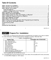
...Switch, as Required 20 STEP 8 Wire Wallplate Terminals 21 STEP 9 Mount The Thermostat 24 STEP 10 Check Thermostat Operation After Programming and Installing 25 STEP 11 Set the Fan and System Switches 28 Troubleshooting Guide ...30 Index ...34 Limited One-Year Warranty ...36 1 69-0733...wire White Rodgers no. 1361 valves. 2 69-0733-3 Compatibility Chart. For more information, call Honeywell Customer Assistance, toll-free 1-800-468-1502. System Type Compatible with CT3400/3455 Gas-Standing Pilot Gas-Electronic Ignition Gas-Fired Boilers Gas-Millivolt Oil-Fired Boilers Oil-Fired ...
...Switch, as Required 20 STEP 8 Wire Wallplate Terminals 21 STEP 9 Mount The Thermostat 24 STEP 10 Check Thermostat Operation After Programming and Installing 25 STEP 11 Set the Fan and System Switches 28 Troubleshooting Guide ...30 Index ...34 Limited One-Year Warranty ...36 1 69-0733...wire White Rodgers no. 1361 valves. 2 69-0733-3 Compatibility Chart. For more information, call Honeywell Customer Assistance, toll-free 1-800-468-1502. System Type Compatible with CT3400/3455 Gas-Standing Pilot Gas-Electronic Ignition Gas-Fired Boilers Gas-Millivolt Oil-Fired Boilers Oil-Fired ...
Owner's Manual
Page 5
... within 20 to 2 months before batteries run out completely. s Install the batteries in chart on these systems. For details, call Honeywell Customer Assistance at 1-800-468-1502. 5 69-0733-3 STEP 3 Before You Program Install the Batteries IMPORTANT: Three AA alkaline batteries are running low, a...for 1 to 30 sec- However, if the display is not compatible with your system, call Honeywell Customer Assistance at 1-800-468-1502. If there are dead or incorrectly installed. However, some hot water (zoned) heating systems have three wires for programming and operation of ...
... within 20 to 2 months before batteries run out completely. s Install the batteries in chart on these systems. For details, call Honeywell Customer Assistance at 1-800-468-1502. 5 69-0733-3 STEP 3 Before You Program Install the Batteries IMPORTANT: Three AA alkaline batteries are running low, a...for 1 to 30 sec- However, if the display is not compatible with your system, call Honeywell Customer Assistance at 1-800-468-1502. If there are dead or incorrectly installed. However, some hot water (zoned) heating systems have three wires for programming and operation of ...
Owner's Manual
Page 6
... back of the thermostat) by turning out one turn on to the thermostat or the wall surface. It normally takes four to eight days after installation for conventional recovery, a s indicator PM SET PT TUE DAYTIME appears in the lower right corner of the ther- tive Intelligent Recovery™ feature. 8 69-0733...
... back of the thermostat) by turning out one turn on to the thermostat or the wall surface. It normally takes four to eight days after installation for conventional recovery, a s indicator PM SET PT TUE DAYTIME appears in the lower right corner of the ther- tive Intelligent Recovery™ feature. 8 69-0733...
Owner's Manual
Page 7
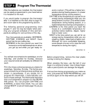
....) DAYTIME is the time period you can program DAYTIME and EVENING, or leave them blank. You can also change NIGHT or cancel it is installed on the wall, skip to page 16, and return later to program the thermostat, it is the time period you can set for an ... weekdays, Saturday, Sunday. If you get up and while you decide not to this programming section. STEP 4 Program The Thermostat After the batteries are installed, the thermostat can be helpful when planning your program schedule of time and temperature settings for various times of the day. The following personal programming...
....) DAYTIME is the time period you can program DAYTIME and EVENING, or leave them blank. You can also change NIGHT or cancel it is installed on the wall, skip to page 16, and return later to program the thermostat, it is the time period you can set for an ... weekdays, Saturday, Sunday. If you get up and while you decide not to this programming section. STEP 4 Program The Thermostat After the batteries are installed, the thermostat can be helpful when planning your program schedule of time and temperature settings for various times of the day. The following personal programming...
Owner's Manual
Page 10
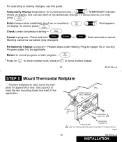
... Program (page 14), as on display, and cancels itself at next scheduled change. Use a pencil to normal program or start program- M5932A 16 69-0733-3 INSTALLATION Temp ; a Press on to move number back; a Temporarily Change temperature for appearance only.
... Program (page 14), as on display, and cancels itself at next scheduled change. Use a pencil to normal program or start program- M5932A 16 69-0733-3 INSTALLATION Temp ; a Press on to move number back; a Temporarily Change temperature for appearance only.

Owner's Manual
Page 11
For firmer material such as follows: 18 69-0733-3 INSTALLATION s Reposition wallplate over holes, pulling wires through wiring opening. s Level for system type: • Hot Water or High Efficiency-Set at the Gravity Air/Water ... Warm Air-Leave at the Hot Water or High Efficiency setting (1A-leave in the illustration as marked. In the unlikely event that you are installing it on another type of system to minimize room temperature swings. If you want longer furnace on -time is factory-set for a warm air, gas...
For firmer material such as follows: 18 69-0733-3 INSTALLATION s Reposition wallplate over holes, pulling wires through wiring opening. s Level for system type: • Hot Water or High Efficiency-Set at the Gravity Air/Water ... Warm Air-Leave at the Hot Water or High Efficiency setting (1A-leave in the illustration as marked. In the unlikely event that you are installing it on another type of system to minimize room temperature swings. If you want longer furnace on -time is factory-set for a warm air, gas...
Owner's Manual
Page 12
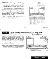
... screws 2A and 2B as necessary using a high efficiency furnace such as a guide. FAN OPERATION SWITCH (SHOWN IN NON ELEC POSITION) M619C 20 69-0733-3 INSTALLATION IMPORTANT: When using the illustration as a 90% or greater AFUE (Average Fuel Utilization Efficiency) unit, leave screw 1A in and screw 1B out one turn... the temperature in degrees Fahrenheit. s The thermostat is connected to the right (ELEC) position. If a 24-hour clock (e.g., military time) or degrees Celsius readings are installed, or the left (NON ELEC) position.
... screws 2A and 2B as necessary using a high efficiency furnace such as a guide. FAN OPERATION SWITCH (SHOWN IN NON ELEC POSITION) M619C 20 69-0733-3 INSTALLATION IMPORTANT: When using the illustration as a 90% or greater AFUE (Average Fuel Utilization Efficiency) unit, leave screw 1A in and screw 1B out one turn... the temperature in degrees Fahrenheit. s The thermostat is connected to the right (ELEC) position. If a 24-hour clock (e.g., military time) or degrees Celsius readings are installed, or the left (NON ELEC) position.

Owner's Manual
Page 13
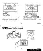
...in the wall with local codes and ordinances. PROVIDE DISCONNECT MEANS AND OVERLOAD PROTECTION AS REQUIRED. M614A 22 69-0733-3 INSTALLATION Either straight or wraparound wiring connections are acceptable (see illustration). s Match the letter of your old thermostat wire with ... OR VALVE COIL FAN RELAY COOLING CONTACTOR COIL 1 1 POWER SUPPLY. FOR STRAIGHT INSERTION- STRIP 7/16 IN. (11MM) In 5-wire installations only, be sure to illustrations on your old thermostat. If unsure about household wiring procedures, call your local heating/air conditioning contractor. ...
...in the wall with local codes and ordinances. PROVIDE DISCONNECT MEANS AND OVERLOAD PROTECTION AS REQUIRED. M614A 22 69-0733-3 INSTALLATION Either straight or wraparound wiring connections are acceptable (see illustration). s Match the letter of your old thermostat wire with ... OR VALVE COIL FAN RELAY COOLING CONTACTOR COIL 1 1 POWER SUPPLY. FOR STRAIGHT INSERTION- STRIP 7/16 IN. (11MM) In 5-wire installations only, be sure to illustrations on your old thermostat. If unsure about household wiring procedures, call your local heating/air conditioning contractor. ...
Owner's Manual
Page 14
... The Thermostat AM MON DAYTIME HEAT ON A. ENGAGE TABS BETWEEN TOP OF THERMOSTAT AND WALLPLATE C. PRESS LOWER EDGE OF CASE TO LATCH M5143 69-0733-3 INSTALLATION SWING COVER OPEN FOR CHECKOUT AND PROGRAMMING AM MON DAYTIME HEAT ON Set Present Day Time Hold Temp Day Morning Run Program Night On Auto...
... The Thermostat AM MON DAYTIME HEAT ON A. ENGAGE TABS BETWEEN TOP OF THERMOSTAT AND WALLPLATE C. PRESS LOWER EDGE OF CASE TO LATCH M5143 69-0733-3 INSTALLATION SWING COVER OPEN FOR CHECKOUT AND PROGRAMMING AM MON DAYTIME HEAT ON Set Present Day Time Hold Temp Day Morning Run Program Night On Auto...
Owner's Manual
Page 15
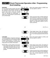
STEP 10 Check Thermostat Operation After Programming And Installing HEATING HEAT OFF COOL Do not check heating system operation by jumpering thermostat terminals at the thermostat. FAN ON AUTO This will damage the thermostat. ...
STEP 10 Check Thermostat Operation After Programming And Installing HEATING HEAT OFF COOL Do not check heating system operation by jumpering thermostat terminals at the thermostat. FAN ON AUTO This will damage the thermostat. ...
Owner's Manual
Page 17
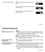
... your heating system. The setting range is 45°F to 88°F (7°C to OFF. Make sure the current day and time are fresh and installed correctly. Reprogram if necessary. ward for the period in question. s Make sure batteries are correct. THEN... Insert back- Do not use anything abrasive on . HEAT...
... your heating system. The setting range is 45°F to 88°F (7°C to OFF. Make sure the current day and time are fresh and installed correctly. Reprogram if necessary. ward for the period in question. s Make sure batteries are correct. THEN... Insert back- Do not use anything abrasive on . HEAT...
Owner's Manual
Page 18
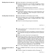
... displays REPL BAT, install fresh batteries. s Check the system fuse or circuit breaker and replace or reset if necessary. s The thermostat has a built-in time delay on thermostat is set to ten minutes after ten minutes and COOL is displayed, contact Honeywell Customer Assistance at 1-... Jumper wires R and W. Heating does not come on. s If temperature setting is higher than current temperature, and COOL is displayed, contact Honeywell Customer Assistance at 1-800-468-1502. s Make sure outdoor disconnect is energized (on thermostat is set to OFF for correct wiring and good ...
... displays REPL BAT, install fresh batteries. s Check the system fuse or circuit breaker and replace or reset if necessary. s The thermostat has a built-in time delay on thermostat is set to ten minutes after ten minutes and COOL is displayed, contact Honeywell Customer Assistance at 1-... Jumper wires R and W. Heating does not come on. s If temperature setting is higher than current temperature, and COOL is displayed, contact Honeywell Customer Assistance at 1-800-468-1502. s Make sure outdoor disconnect is energized (on thermostat is set to OFF for correct wiring and good ...
Owner's Manual
Page 19
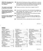
... is too short or too long. The system cycle length is factory-calibrated and cannot be adjusted. 33 69-0733-3 Index Adaptive Intelligent Recovery 7,8 Batteries, installation 6 Batteries, replacement ........ 6,7 Blinking display 6 Canceling programs 15 Change temperature 15 Checking current setting ....... 15 Clock display 19 Conventional Recovery ....... 7,8 Cooling temperatures ........ 9,11,12,14 Current...
... is too short or too long. The system cycle length is factory-calibrated and cannot be adjusted. 33 69-0733-3 Index Adaptive Intelligent Recovery 7,8 Batteries, installation 6 Batteries, replacement ........ 6,7 Blinking display 6 Canceling programs 15 Change temperature 15 Checking current setting ....... 15 Clock display 19 Conventional Recovery ....... 7,8 Cooling temperatures ........ 9,11,12,14 Current...


