
Owner's Manual
Page 1
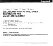
Rev. 7-91 aHoneywell Inc. 1991 Form Number 69-0273-9 CTl501-24 V gas or oil heat/cool. NOT FOR USE ON LINE VOLTAGE (120 V) SYSTEMS. INSTALLATION MANUAL Any questionsconcerningthe applicationofthis thermostat should be directedto HoneywellConsumer Services at 1-800-468-1502, Monday-Friday 7 3 0 a.m.-500 pm., Central time. S.M. CTI502--24 V central electric heat/cool or single stage heat pump without auxiliary heat. CTI503-750 millivolt heat. CTl500, CT1501, CT1502, CT1503 ELECTROMECHANICAL FUEL SAVER THERMOSTAT AND WALLPLATEEUBBASE CTI500-24 V gas or oil heat.
Rev. 7-91 aHoneywell Inc. 1991 Form Number 69-0273-9 CTl501-24 V gas or oil heat/cool. NOT FOR USE ON LINE VOLTAGE (120 V) SYSTEMS. INSTALLATION MANUAL Any questionsconcerningthe applicationofthis thermostat should be directedto HoneywellConsumer Services at 1-800-468-1502, Monday-Friday 7 3 0 a.m.-500 pm., Central time. S.M. CTI502--24 V central electric heat/cool or single stage heat pump without auxiliary heat. CTI503-750 millivolt heat. CTl500, CT1501, CT1502, CT1503 ELECTROMECHANICAL FUEL SAVER THERMOSTAT AND WALLPLATEEUBBASE CTI500-24 V gas or oil heat.
Owner's Manual
Page 2
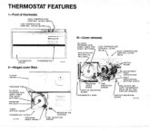
H E L D O N BY TWO CAPTIVE SCREWS.) CAPTIVE MOUNTING ANTICIPATOR HIND THERMOSTAT. Ill-Cover removed. 24 HOUR PROGRAM DIAL 'THERMOSTAT COVER THERMOMETER 1 11.711 Il-Hinged cover lifted. .. .~ . ,..... . HlGH TEMPERATURE 1 CONTROL LEVER (RED) LOW TEMPERATURE CONTROL LEVER (BLUE)- THERMOSTAT FEATURES I-Front of thermostat. PROGRAM PINS A "---
H E L D O N BY TWO CAPTIVE SCREWS.) CAPTIVE MOUNTING ANTICIPATOR HIND THERMOSTAT. Ill-Cover removed. 24 HOUR PROGRAM DIAL 'THERMOSTAT COVER THERMOMETER 1 11.711 Il-Hinged cover lifted. .. .~ . ,..... . HlGH TEMPERATURE 1 CONTROL LEVER (RED) LOW TEMPERATURE CONTROL LEVER (BLUE)- THERMOSTAT FEATURES I-Front of thermostat. PROGRAM PINS A "---
Owner's Manual
Page 3
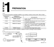
...included in heatino. [ 750 mill volt single-stage heating system. CT1501 Q682A1079 Subbase 4- IF NEEDED TO LABELWIRESASTHEYARE OISCONNECTED FROM OLD THERMOSTAT or 5-wire, 15 to control the fan in package to 30 volt control circuit. For single stage heat pump or central ...electric heatinglcooling systems that require the thermostat to 30 volt control circuit For gas or oil heating/cooling system. "1k PREPARATION ((1 THERMOSTAT MODEL SUBBASE OR WALLPLATE INCLUDED FOR USE WITH CT1500 199986C Wallplate 2-wire, 15 to 30 volt control circuit For...
...included in heatino. [ 750 mill volt single-stage heating system. CT1501 Q682A1079 Subbase 4- IF NEEDED TO LABELWIRESASTHEYARE OISCONNECTED FROM OLD THERMOSTAT or 5-wire, 15 to control the fan in package to 30 volt control circuit. For single stage heat pump or central ...electric heatinglcooling systems that require the thermostat to 30 volt control circuit For gas or oil heating/cooling system. "1k PREPARATION ((1 THERMOSTAT MODEL SUBBASE OR WALLPLATE INCLUDED FOR USE WITH CT1500 199986C Wallplate 2-wire, 15 to 30 volt control circuit For...
Owner's Manual
Page 4
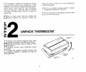
Call Honeywell Consumer Services (1-800-468-1502) for ordering information, Monday-Friday, 7:30 a.m. to the heatingfcooling System at the main fuse panel. Central time. Turn off power to 500 p.m. i2 F UNPACK THERMOSTAT 0 0Remove and discard shipping wrap. IFT OVER SCREWS 12.612 2 Test to... appropriate figure under step 4). Ifwallplate or subbase is below 50' F [looC]. Save package of screws, instructions and receipt Remove thermostat cover by lifting up from the bottom. 0Carefully remove insert protecting switch bulbs. 0Loosen two captive mounting screws, and separate wallplate or...
Call Honeywell Consumer Services (1-800-468-1502) for ordering information, Monday-Friday, 7:30 a.m. to the heatingfcooling System at the main fuse panel. Central time. Turn off power to 500 p.m. i2 F UNPACK THERMOSTAT 0 0Remove and discard shipping wrap. IFT OVER SCREWS 12.612 2 Test to... appropriate figure under step 4). Ifwallplate or subbase is below 50' F [looC]. Save package of screws, instructions and receipt Remove thermostat cover by lifting up from the bottom. 0Carefully remove insert protecting switch bulbs. 0Loosen two captive mounting screws, and separate wallplate or...
Owner's Manual
Page 5
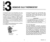
Move on a system with B or 0 terminals. If there are replacing a Honeywell Chronotherm thermostat,you recognize the heat anticipator.) Make a note h e r e l l o f that go to the clock terminals on the Chronotherm thermostat wiring wallplate. If you are only two wires, labeling is not necessary. Record the colors ... that anticipator setting for a screw that locks the cover on your system. Do not allow them to next paragraph. "3 F REMOVE OLD THERMOSTAT 0 0Remove cover of the wires. 3 69-0273-9 ~ Disconnect wires from the bottom, check for future reference. Tape each wire and ...
Move on a system with B or 0 terminals. If there are replacing a Honeywell Chronotherm thermostat,you recognize the heat anticipator.) Make a note h e r e l l o f that go to the clock terminals on the Chronotherm thermostat wiring wallplate. If you are only two wires, labeling is not necessary. Record the colors ... that anticipator setting for a screw that locks the cover on your system. Do not allow them to next paragraph. "3 F REMOVE OLD THERMOSTAT 0 0Remove cover of the wires. 3 69-0273-9 ~ Disconnect wires from the bottom, check for future reference. Tape each wire and ...
Owner's Manual
Page 8
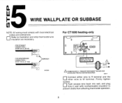
"-r.n.~S.T.F..ldilR.U.T CONNECTION- F. For CT1500 heating-only 0 , FOR WRAPAROUND CONNECTIONSTRlP7116In. [11 mml BARRIER I I A POWER SUPPLY. PROVIDE DISCONNECT MEANS AND OVERLOAD PROTECTIONAS REOUIRED. Firmly tighten screws. 0Push excess wire back into ... In wall with local electrical codes and ordinances. WIRE WALLPLATE OR SUBBASE 0 .: -MOTE:All wiring must comply with nonflammable Insulation to prevent drafts from affecting thermostat operation. 6 Wlll Connect either wire to R terminal and the other wire to illustration and strip...
"-r.n.~S.T.F..ldilR.U.T CONNECTION- F. For CT1500 heating-only 0 , FOR WRAPAROUND CONNECTIONSTRlP7116In. [11 mml BARRIER I I A POWER SUPPLY. PROVIDE DISCONNECT MEANS AND OVERLOAD PROTECTIONAS REOUIRED. Firmly tighten screws. 0Push excess wire back into ... In wall with local electrical codes and ordinances. WIRE WALLPLATE OR SUBBASE 0 .: -MOTE:All wiring must comply with nonflammable Insulation to prevent drafts from affecting thermostat operation. 6 Wlll Connect either wire to R terminal and the other wire to illustration and strip...
Owner's Manual
Page 10
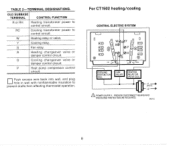
... A POWER SUPPLY. G Fan relay. OLDSUBBASE TERMINAL CONTROL FUNCTION R or RH Heating transformer power to control circuit RC Cooling transformer power to prevent drafts from affecting thermostat operation. P Heat pump compressor control Push excess wire back into wall. and plug hole in wall with nonflammable insulation to control circuit.
... A POWER SUPPLY. G Fan relay. OLDSUBBASE TERMINAL CONTROL FUNCTION R or RH Heating transformer power to control circuit RC Cooling transformer power to prevent drafts from affecting thermostat operation. P Heat pump compressor control Push excess wire back into wall. and plug hole in wall with nonflammable insulation to control circuit.

Owner's Manual
Page 11
...SUPPLY PROVIDE DISCONNECT MEANS AND OVERLOPD PROTECTION AS REQUIRED A IFCOMPRESSOR ISCONNECTEDTO OLDTHERMOSTATS "YTERMINALWITH A JUMPERTO"W, USE NEW THERMOSTATS "PTERMINALFORCOMPRESSOR. IFOLOTHERMOSTATHAS ONE WIRETO"Y"AND0NE TO " W . U S t ' Y AND " W ' O N NEW THERMOSTAT, DO NOT U S E " P . CT1502, continued SINGLE STAGE HEAT PUMP (WITHOUT AUXILIARY HEAT... insulation to prevent drafts from affecting thermostat operation. IF OLD THERMOSTAT USES A W2 (AUXILIARY OR EMERGENCY HEAT) TERMINAL, THIS THERMOSTAT MAY NOT BE USED THIS THERMOSTAT IS NOT DESIGNED TO CONTROL AUXILIARY HEAT...
...SUPPLY PROVIDE DISCONNECT MEANS AND OVERLOPD PROTECTION AS REQUIRED A IFCOMPRESSOR ISCONNECTEDTO OLDTHERMOSTATS "YTERMINALWITH A JUMPERTO"W, USE NEW THERMOSTATS "PTERMINALFORCOMPRESSOR. IFOLOTHERMOSTATHAS ONE WIRETO"Y"AND0NE TO " W . U S t ' Y AND " W ' O N NEW THERMOSTAT, DO NOT U S E " P . CT1502, continued SINGLE STAGE HEAT PUMP (WITHOUT AUXILIARY HEAT... insulation to prevent drafts from affecting thermostat operation. IF OLD THERMOSTAT USES A W2 (AUXILIARY OR EMERGENCY HEAT) TERMINAL, THIS THERMOSTAT MAY NOT BE USED THIS THERMOSTAT IS NOT DESIGNED TO CONTROL AUXILIARY HEAT...

Owner's Manual
Page 12
Do NOT cycle heating system until Step 7 is completed. 10 L MOUNT THE THERMOSTAT or subbase as shown in illustration. -
Do NOT cycle heating system until Step 7 is completed. 10 L MOUNT THE THERMOSTAT or subbase as shown in illustration. -
Owner's Manual
Page 13
... the ammeter for your system. This i s the number you wrote in the box in room temperature swings or burn out the anticipator and void the thermostat warranty. The primary control is usually a gas valve a relay or burner controi box, Aquastat controller or zone valve with the... thermostat wires connected to it These controls are usually located behind the furnace cover See next illustration If current rating is still unavailable, proceed as follows: ...
... the ammeter for your system. This i s the number you wrote in the box in room temperature swings or burn out the anticipator and void the thermostat warranty. The primary control is usually a gas valve a relay or burner controi box, Aquastat controller or zone valve with the... thermostat wires connected to it These controls are usually located behind the furnace cover See next illustration If current rating is still unavailable, proceed as follows: ...
Owner's Manual
Page 14
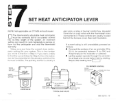
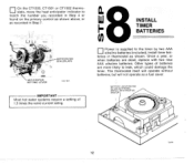
The thermostat itself will operate without batteries, but will not operate as shown. Other types of batteries are dead, replace with two new AAA alkaline batteries. CT1501 or CT1502 thermostats, move the heat anticipator indicator to leak, which could damage the timer. Once a year, or when batteries are more likely to match the number you recorded in Step 4 or found on the primary control as shown above, or as recorded in Step 7 "8INSTALL F TIMER BATTERIES 0 \ANTICIPATOR SETTING LEVER 11,7164\ teries in thermostat as a fuel saver. 12 On the CT1500.
The thermostat itself will operate without batteries, but will not operate as shown. Other types of batteries are dead, replace with two new AAA alkaline batteries. CT1501 or CT1502 thermostats, move the heat anticipator indicator to leak, which could damage the timer. Once a year, or when batteries are more likely to match the number you recorded in Step 4 or found on the primary control as shown above, or as recorded in Step 7 "8INSTALL F TIMER BATTERIES 0 \ANTICIPATOR SETTING LEVER 11,7164\ teries in thermostat as a fuel saver. 12 On the CT1500.
Owner's Manual
Page 16
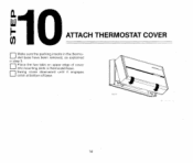
"10 0I- ATTACH THERMOSTAT COVER 0Make sure the packing inserts in thermostat base 0Swing cover downward until it engages catch at bottom of base .. 14 as explained in step 3 0Place the two tabs on upper edge of cover into mounting slots in the thermostat base have been removed.
"10 0I- ATTACH THERMOSTAT COVER 0Make sure the packing inserts in thermostat base 0Swing cover downward until it engages catch at bottom of base .. 14 as explained in step 3 0Place the two tabs on upper edge of cover into mounting slots in the thermostat base have been removed.
Owner's Manual
Page 17
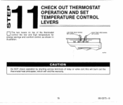
cin l1CHECK OUT THERMOSTAT OPERATION AND SET b TEMPERATURE CONTROL LEVERS The two levers on top of relay or valve coil; this will burn out the thermostat heat anticipator, which will void the warranty. I 15 69-0273-9 ~ LOW TEMP.lBL"E MARK1 SET LEVER 1 Do NOT check operation by shorting across terminals of the thermostat control the low and high temperature for energy savings and comfort control, as shown in illustration.
cin l1CHECK OUT THERMOSTAT OPERATION AND SET b TEMPERATURE CONTROL LEVERS The two levers on top of relay or valve coil; this will burn out the thermostat heat anticipator, which will void the warranty. I 15 69-0273-9 ~ LOW TEMP.lBL"E MARK1 SET LEVER 1 Do NOT check operation by shorting across terminals of the thermostat control the low and high temperature for energy savings and comfort control, as shown in illustration.
Owner's Manual
Page 18
... lever at COOL and the fan switch lever at AUTO. 0 Push both temperature: levers to various positions. IMPORTANT If thermostat fails any position. 0 Place the system switch at HEAT. IMPORTANT If thermostat fails any time delay that may be built into the compressor control circuit. 0 Movebothleverstogether5°F[30C]aboveroom temperature. The heat...
... lever at COOL and the fan switch lever at AUTO. 0 Push both temperature: levers to various positions. IMPORTANT If thermostat fails any position. 0 Place the system switch at HEAT. IMPORTANT If thermostat fails any time delay that may be built into the compressor control circuit. 0 Movebothleverstogether5°F[30C]aboveroom temperature. The heat...
Owner's Manual
Page 19
Move the blue lever to the energy savings temperature you want for normal comfort periods. IF YOU HAVE OUESTIONS REGARDING THE INSTALLATION OF THE HONEYWELL FUEL SAVER THERMOSTAT, PLEASECALL OUR TOLLFREE CONSUMER SERVICES GROUP NUMBER AT 1-800-468-1502, MONDAY-FRIDAY, 7:30 AM - 5:OO PM CENTRALTIME. 17 69-0273-9 For cooling season: 0 Move...
Move the blue lever to the energy savings temperature you want for normal comfort periods. IF YOU HAVE OUESTIONS REGARDING THE INSTALLATION OF THE HONEYWELL FUEL SAVER THERMOSTAT, PLEASECALL OUR TOLLFREE CONSUMER SERVICES GROUP NUMBER AT 1-800-468-1502, MONDAY-FRIDAY, 7:30 AM - 5:OO PM CENTRALTIME. 17 69-0273-9 For cooling season: 0 Move...


