User Manual
Page 3
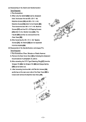
...be separated from the Handle [20]. (5) Disassembly of the Switch and Handle Section: Tools Required: • Plus Screwdriver A. Tapping Screws [21], the Switch [22] can be taken out. Machine Screws [18] and M5 x 16 -Hd. Remove the Saw Cover Ass'y [3] by following the disassembly procedures in paragraph (3),... above. Screws [74], gently tap on the saw cover side of the Gear Case [53] to loosen and remove the Spindle Gear Ass'y [75]. --- 3 --- When only the Switch [22] must be removed from the Stopper Pin [52], the Stopper Pin [...
...be separated from the Handle [20]. (5) Disassembly of the Switch and Handle Section: Tools Required: • Plus Screwdriver A. Tapping Screws [21], the Switch [22] can be taken out. Machine Screws [18] and M5 x 16 -Hd. Remove the Saw Cover Ass'y [3] by following the disassembly procedures in paragraph (3),... above. Screws [74], gently tap on the saw cover side of the Gear Case [53] to loosen and remove the Spindle Gear Ass'y [75]. --- 3 --- When only the Switch [22] must be removed from the Stopper Pin [52], the Stopper Pin [...
User Manual
Page 4
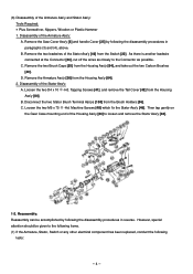
Remove the Saw Cover Ass'y [3] and handle Cover [25] by following the disassembly procedures in paragraphs (3) and (4), above. C. Loosen the two M5 x 75 -Hd. (6) Disassembly of the Stator Ass'y [46] from the Switch [22]. Remove the Armature Ass'y [36] from the Brush Holders [56]. Loosen ...the two D4 x 10 -Hd. Reassembly: Reassembly can be given to the following items. (1) If the Armature, Stator, Switch or any other electrical component has been replaced, conduct the following the disassembly procedures in reverse. Disconnect the two Stator Brush Terminal Ass'ys...
Remove the Saw Cover Ass'y [3] and handle Cover [25] by following the disassembly procedures in paragraphs (3) and (4), above. C. Loosen the two M5 x 75 -Hd. (6) Disassembly of the Stator Ass'y [46] from the Switch [22]. Remove the Armature Ass'y [36] from the Brush Holders [56]. Loosen ...the two D4 x 10 -Hd. Reassembly: Reassembly can be given to the following items. (1) If the Armature, Stator, Switch or any other electrical component has been replaced, conduct the following the disassembly procedures in reverse. Disconnect the two Stator Brush Terminal Ass'ys...
User Manual
Page 5
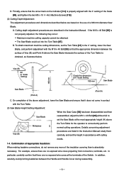
..., a dielectric strength test should be in exact center. After electrical testing has been completed, connect the plug to the polycarbonate portion of the Switch Handle. (3) If the M12 Nut and M12 Lock Nut on the Hinge, causing uneven cutting of the Table Insert mounting groove, as illustrated ... exposed metal portions of the frame with the smooth movement of 7 megohms. B. With the main switch turned ON, measure the insulation resistance between the plug prongs and exposed metal portions of the Saw Blade (or Dummy Disc), and adjust Vise (B) as necessary so that the D12.7 Steel Ball...
..., a dielectric strength test should be in exact center. After electrical testing has been completed, connect the plug to the polycarbonate portion of the Switch Handle. (3) If the M12 Nut and M12 Lock Nut on the Hinge, causing uneven cutting of the Table Insert mounting groove, as illustrated ... exposed metal portions of the frame with the smooth movement of 7 megohms. B. With the main switch turned ON, measure the insulation resistance between the plug prongs and exposed metal portions of the Saw Blade (or Dummy Disc), and adjust Vise (B) as necessary so that the D12.7 Steel Ball...
User Manual
Page 6
... Instruction Manual; In addition, carefully avoid pinching leadwires between the surface of Vise (B) and Point A (where the Saw Blade intersects the surface of the Switch. Confirmation of Appropriate Insulation: When making leadwire connections, do not remove any more of the above Workpiece H the... Turn Table for the operator to set the height in contact with the Turn Table. (3) Saw Blade Height Setting Adjustment:...
... Instruction Manual; In addition, carefully avoid pinching leadwires between the surface of Vise (B) and Point A (where the Saw Blade intersects the surface of the Switch. Confirmation of Appropriate Insulation: When making leadwire connections, do not remove any more of the above Workpiece H the... Turn Table for the operator to set the height in contact with the Turn Table. (3) Saw Blade Height Setting Adjustment:...
User Manual
Page 7
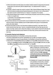
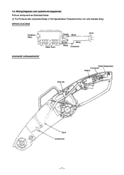
1-5. and Canada Only): WIRING DIAGRAM Armature Ass'y Stator Ass'y Switch Black Brown White White Connector Cord LEADWIRE ARRANGEMENT Noise Suppressor Connector Switch Tube (A) Cord Cord Armor --- 7 --- Wiring Diagrams and Leadwire Arrangements: Perform wiring work as illustrated below. (1) For Products with a Dynamic Brake (115V Specification Products for the U.S.
1-5. and Canada Only): WIRING DIAGRAM Armature Ass'y Stator Ass'y Switch Black Brown White White Connector Cord LEADWIRE ARRANGEMENT Noise Suppressor Connector Switch Tube (A) Cord Cord Armor --- 7 --- Wiring Diagrams and Leadwire Arrangements: Perform wiring work as illustrated below. (1) For Products with a Dynamic Brake (115V Specification Products for the U.S.
User Manual
Page 8
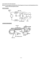
WIRING DIAGRAM Armature Ass'y Stator Ass'y LEADWIRE ARRANGEMENT Noise Suppressor Switch Vinyl Tube Black Red Black Red Green Terminal (w/o insulation tube) M5 x 75 Machine Screw Stator Core Noise Suppressor Yellow/Green Connector --- 8 --- (2) For Products with a Noise Suppressor: [NOTE] The wiring diagram for products without a Noise Suppressor is the same as that illustrated below with the exception of the Noise Suppressor section.
WIRING DIAGRAM Armature Ass'y Stator Ass'y LEADWIRE ARRANGEMENT Noise Suppressor Switch Vinyl Tube Black Red Black Red Green Terminal (w/o insulation tube) M5 x 75 Machine Screw Stator Core Noise Suppressor Yellow/Green Connector --- 8 --- (2) For Products with a Noise Suppressor: [NOTE] The wiring diagram for products without a Noise Suppressor is the same as that illustrated below with the exception of the Noise Suppressor section.


