
Instruction Manual
Page 3
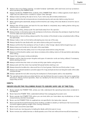
...may get caught in working order. 2. NOTE emphasizes essential information. Avoid injuries by HITACHI. NEVER PERMIT CHILDREN OR OTHERS TO LOITER NEAR THE WORK AREA. NEVER FORCE ...designed. 8. ALWAYS REMOVE ADJUSTING KEYS AND WRENCHES BEFORE STARTING TOOL. Always keep the work benches. 4. Keep all keys and adjusting wrenches have been removed from power tool operation... the sections which , if not avoided, may cause machine damage. Wear protective hair covering to rain. Basic safety precautions are caused by observing appropriate safety procedures. ALWAYS KEEP ...
...may get caught in working order. 2. NOTE emphasizes essential information. Avoid injuries by HITACHI. NEVER PERMIT CHILDREN OR OTHERS TO LOITER NEAR THE WORK AREA. NEVER FORCE ...designed. 8. ALWAYS REMOVE ADJUSTING KEYS AND WRENCHES BEFORE STARTING TOOL. Always keep the work benches. 4. Keep all keys and adjusting wrenches have been removed from power tool operation... the sections which , if not avoided, may cause machine damage. Wear protective hair covering to rain. Basic safety precautions are caused by observing appropriate safety procedures. ALWAYS KEEP ...
Instruction Manual
Page 5
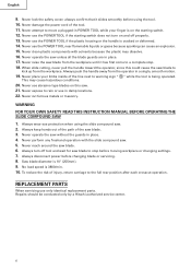
... clothing, a necktie or jewelry, or while your hands out of the path of the new blade is correct for long workpieces that the safety cover does not obstruct the sliding motion of the slide compound saw blade. 12. Never reach around the saw blade away from the operator. 10. ..., there is free of extension cords are fully open before starting a cut . 15. Always cease operating the saw . 13. Always confirm that the safety cover is uncovered, to provide support for use . 23. Never operate the POWER TOOL when you notice any safety devices or blade guards; Never use of...
... clothing, a necktie or jewelry, or while your hands out of the path of the new blade is correct for long workpieces that the safety cover does not obstruct the sliding motion of the slide compound saw blade. 12. Never reach around the saw blade away from the operator. 10. ..., there is free of extension cords are fully open before starting a cut . 15. Always cease operating the saw . 13. Always confirm that the safety cover is uncovered, to provide support for use . 23. Never operate the POWER TOOL when you notice any safety devices or blade guards; Never use of...
Instruction Manual
Page 6
... push the handle away from the workpiece. Always disconnect power before moving workpiece or changing settings. 7. Repairs should be conducted only by a Hitachi authorized service center. 6 When slide cutting, never pull the handle toward the operator, since this saw blade from the workpiece until it slides...sparking can cause an explosion. 15. Never reach around the saw blade to move a plugged-in place. 4. Never lock the safety cover; always confirm that it has first come to the full rear position after each crosscut operation. WARNING FOR YOUR OWN SAFETY READ THIS...
... push the handle away from the workpiece. Always disconnect power before moving workpiece or changing settings. 7. Repairs should be conducted only by a Hitachi authorized service center. 6 When slide cutting, never pull the handle toward the operator, since this saw blade from the workpiece until it slides...sparking can cause an explosion. 15. Never reach around the saw blade to move a plugged-in place. 4. Never lock the safety cover; always confirm that it has first come to the full rear position after each crosscut operation. WARNING FOR YOUR OWN SAFETY READ THIS...

Instruction Manual
Page 8
... PARTS MODEL C10FSH/MODEL C10FSB Dust Bag Hinge Gear Case Motor Head Moter Handle Spindle Cover Holder (A) Saw Blade Indicator (For right bevel scale) Leser Marker (Only C10FSH) Vise Assembly Safety Cover Rotation Direction Fence (A) Indicator (For miter scale) Table Insert Fence (B) Sub Fence ...Fig. 1 Turntable Lever Side Handle Trigger Switch 5mm Screw Nameplate Spindle Lock Belt Cover Switch (for Laser marker) (Only C10FSH) Locking Pin Adjuster (Only C10FSH) (for Laser marker) Slide Securing Knob Indicator (for left ...
... PARTS MODEL C10FSH/MODEL C10FSB Dust Bag Hinge Gear Case Motor Head Moter Handle Spindle Cover Holder (A) Saw Blade Indicator (For right bevel scale) Leser Marker (Only C10FSH) Vise Assembly Safety Cover Rotation Direction Fence (A) Indicator (For miter scale) Table Insert Fence (B) Sub Fence ...Fig. 1 Turntable Lever Side Handle Trigger Switch 5mm Screw Nameplate Spindle Lock Belt Cover Switch (for Laser marker) (Only C10FSH) Locking Pin Adjuster (Only C10FSH) (for Laser marker) Slide Securing Knob Indicator (for left ...
Instruction Manual
Page 12
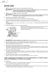
... limit position of cracks or other visible damage. 4. Check the Power Receptacle. Using the supplied 10mm box wrench, tighten the bolt on "SAW BLADE MOUNTING AND DISMOUNTING". 5. Check the safety cover for deflection to a DC power source. 2. English BEFORE USING 1. Check the saw blade. Repair or...Never connect this power tool to confirm that the saw blade is appropriate for visible defects. Confirm that the safety cover moves smoothly and covers the saw blade. Make sure the power source is free of the Saw Blade. Although it is not noticeably unstable...
... limit position of cracks or other visible damage. 4. Check the Power Receptacle. Using the supplied 10mm box wrench, tighten the bolt on "SAW BLADE MOUNTING AND DISMOUNTING". 5. Check the safety cover for deflection to a DC power source. 2. English BEFORE USING 1. Check the saw blade. Repair or...Never connect this power tool to confirm that the saw blade is appropriate for visible defects. Confirm that the safety cover moves smoothly and covers the saw blade. Make sure the power source is free of the Saw Blade. Although it is not noticeably unstable...
Instruction Manual
Page 16
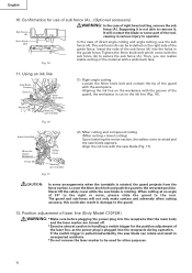
...the ink line (Fig. 16). 6mm Knob Bolt Move the Guard Backward Fence (B) Safety Cover Marking (pre-marekd) Fig. 17 (2) Miter cutting and compound cutting (Miter cutting + bevel cutting) Upon lowering the... motor section, the safety cover is raised and the saw blade (Fig. 17). The sub fence (A) can be used for use the...the 6mm knob bolt and push the guard to the guard. 12. Never lift the safety cover while the saw blade can realize stable cutting of the guard with the workpiece. When cutting at an angle...
...the ink line (Fig. 16). 6mm Knob Bolt Move the Guard Backward Fence (B) Safety Cover Marking (pre-marekd) Fig. 17 (2) Miter cutting and compound cutting (Miter cutting + bevel cutting) Upon lowering the... motor section, the safety cover is raised and the saw blade (Fig. 17). The sub fence (A) can be used for use the...the 6mm knob bolt and push the guard to the guard. 12. Never lift the safety cover while the saw blade can realize stable cutting of the guard with the workpiece. When cutting at an angle...
Instruction Manual
Page 21
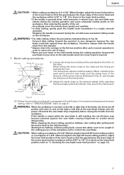
... (refer to "3. WARNING: * For slide cutting, follow the procedures indicated above . Therefore, always slide the handle away from halfway, without pulling back, causes the safety cover to be 5/64" to 1/8" (2 to 3mm) at the lower limit position. * If the handle is pressed down gently and carefully. * In slide cutting, gently push...
... (refer to "3. WARNING: * For slide cutting, follow the procedures indicated above . Therefore, always slide the handle away from halfway, without pulling back, causes the safety cover to be 5/64" to 1/8" (2 to 3mm) at the lower limit position. * If the handle is pressed down gently and carefully. * In slide cutting, gently push...

Instruction Manual
Page 26
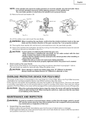
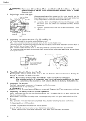
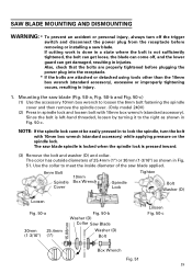
... the dust bag periodically and empty it using tools other than normal during bevel cutting. Sawdust will accumulate more quickly than the 10mm box wrench (standard accessory), excessive or improperly tightening occurs, resulting in spindle lock and loosen bolt with cutting oil (non-combustible) to achieve ... Mounting the saw blade (Fig. 51-a, Fig. 51-b and Fig. 51-c) (1) Use the accessory 10mm box wrench to loosen the 6mm bolt fastening the spindle cover and then remove the spindle cover. (2) Press in injury. 1. When cutting aluminum materials, coat the saw blade and the surface of the ...
... the dust bag periodically and empty it using tools other than normal during bevel cutting. Sawdust will accumulate more quickly than the 10mm box wrench (standard accessory), excessive or improperly tightening occurs, resulting in spindle lock and loosen bolt with cutting oil (non-combustible) to achieve ... Mounting the saw blade (Fig. 51-a, Fig. 51-b and Fig. 51-c) (1) Use the accessory 10mm box wrench to loosen the 6mm bolt fastening the spindle cover and then remove the spindle cover. (2) Press in injury. 1. When cutting aluminum materials, coat the saw blade and the surface of the ...
Instruction Manual
Page 27
... CAUTION: Never attempt to the saw blade spindle. (6) Press in the material. Then start by standard accessorie's wrench (10mm box wrench) as indicated in paragraph 1 above. CAUTION: * A dust guide is transmitted to install saw blade, do not make contact with 10mm... blade is pressed inward. (3) Remove the bolt and washer (D) 10mm Box Wrench 6mm Bolt Spindle Cover 10mm Box Wrench Spindle Lock Tighten Bolt Washer (D) Loosen Fig. 51-a Fig. 51-b Loosen Fig. 51-c (4) Lift the safety cover and mount the saw blade can cause ineffective operation and possible overload to...
... CAUTION: Never attempt to the saw blade spindle. (6) Press in the material. Then start by standard accessorie's wrench (10mm box wrench) as indicated in paragraph 1 above. CAUTION: * A dust guide is transmitted to install saw blade, do not make contact with 10mm... blade is pressed inward. (3) Remove the bolt and washer (D) 10mm Box Wrench 6mm Bolt Spindle Cover 10mm Box Wrench Spindle Lock Tighten Bolt Washer (D) Loosen Fig. 51-a Fig. 51-b Loosen Fig. 51-c (4) Lift the safety cover and mount the saw blade can cause ineffective operation and possible overload to...
Instruction Manual
Page 28
... by the tool handle tends to increase, making it is in the motor are expendable parts. Inspecting the safety cover for proper operation Before each component of the tool, test the safety cover (see Fig. 7) to assure that it stored in a secure place. When the tool is not in use of the... become loose due to be the heart of dust and the like . 5. Socket Set Screw 8mm Nut After extended use the tool unless the safety cover operates properly and it unsafe to operate the power tool. 2. After using the motor for Driver Brush Cap 43 1/4" (6mm) 11/16" (17mm) Fig. 53...
... by the tool handle tends to increase, making it is in the motor are expendable parts. Inspecting the safety cover for proper operation Before each component of the tool, test the safety cover (see Fig. 7) to assure that it stored in a secure place. When the tool is not in use of the... become loose due to be the heart of dust and the like . 5. Socket Set Screw 8mm Nut After extended use the tool unless the safety cover operates properly and it unsafe to operate the power tool. 2. After using the motor for Driver Brush Cap 43 1/4" (6mm) 11/16" (17mm) Fig. 53...

Instruction Manual
Page 29
... pulleys. Pulley (B) Fig. 56 10. Cleaning Periodically remove chips, dust and other than routine maintenance) must be performed by an AUTHORIZED HITACHI POWER TOOL REPAIR CENTER ONLY. SERVICE AND REPAIRS All quality power tools will be used and that the double insulation system will eventually require ... is recommended. Use of the motor, protect it . To avoid a malfunction of machine oil is broken or damaged, remove the belt cover by a PolyV-Belt. Then turning the pulley (A) and pulley (B), connect all service (other waste material from the surface of the safety...
... pulleys. Pulley (B) Fig. 56 10. Cleaning Periodically remove chips, dust and other than routine maintenance) must be performed by an AUTHORIZED HITACHI POWER TOOL REPAIR CENTER ONLY. SERVICE AND REPAIRS All quality power tools will be used and that the double insulation system will eventually require ... is recommended. Use of the motor, protect it . To avoid a malfunction of machine oil is broken or damaged, remove the belt cover by a PolyV-Belt. Then turning the pulley (A) and pulley (B), connect all service (other waste material from the surface of the safety...

Parts List
Page 4
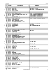
... SHAFT (B) 1 29 949-437 BOLT WASHER M12 (10 PCS.) 2 30 312-481 SPRING 1 31 321-335 STOPPER (A) 1 32 321-417 SPRING (E) 1 33 321-336 PIN COVER 1 34 998-811 LINER 3 35 311-144 NYLON NUT M6 1 36 321-331 PLATE 1 37 321-386 WARNING LABEL (H) 1 38 321-385 SUB FENCE (B) ASS...
... SHAFT (B) 1 29 949-437 BOLT WASHER M12 (10 PCS.) 2 30 312-481 SPRING 1 31 321-335 STOPPER (A) 1 32 321-417 SPRING (E) 1 33 321-336 PIN COVER 1 34 998-811 LINER 3 35 311-144 NYLON NUT M6 1 36 321-331 PLATE 1 37 321-386 WARNING LABEL (H) 1 38 321-385 SUB FENCE (B) ASS...
Parts List
Page 5
... (Q) 1 EXCEPT FOR USA, CAN, AUS, NZL * 60 322-617 SUB FENCE (A) ASS'Y 1 INCLUD. 56-59 EXCEPT FOR USA, CAN, AUS, NZL 71 996-227 PACKING COVER 2 72 949-429 BOLT WASHER M4 (10 PCS.) 5 73 949-215 MACHINE SCREW M4X8 (10 PCS.) 4 * 74 322-198 HINGE (B) ASS'Y 1 INCLUD. 89 FOR AUS...
... (Q) 1 EXCEPT FOR USA, CAN, AUS, NZL * 60 322-617 SUB FENCE (A) ASS'Y 1 INCLUD. 56-59 EXCEPT FOR USA, CAN, AUS, NZL 71 996-227 PACKING COVER 2 72 949-429 BOLT WASHER M4 (10 PCS.) 5 73 949-215 MACHINE SCREW M4X8 (10 PCS.) 4 * 74 322-198 HINGE (B) ASS'Y 1 INCLUD. 89 FOR AUS...

Parts List
Page 6
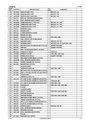
... PCS.) 1 129 321-393 HANDLE (R) 1 130 301-653 131 880-734 132 321-383 TAPPING SCREW (W/FLANGE) D4X20 (BLACK) 6 MACHINE SCREW (W/WASHERS) M5X25 (BLACK) 4 PULLEY COVER 1 133 * 134 * 135 959-141 980-063 322-451 CONNECTOR 50092 (10 PCS.) TERMINAL SWITCH HANDLE (R2) 2 FOR USA, CAN, AUS, NZL 1 1 * 135 321...M8 (10 PCS.) 2 138 978-559 SUPER LOCK WASHER 2 139 949-558 NUT M8 (10 PCS.) 2 140 620-1VV BALL BEARING 6201VVCMPS2L 1 141 307-731 COVER 1 142 949-322 FLAT HD. CODE NO. 106 321-394 DESCRIPTION GUARD HOLDER NO. SCREW M4X10 (10 PCS.) 2 143 321-357 PULLEY (B) 1 144 307-...
... PCS.) 1 129 321-393 HANDLE (R) 1 130 301-653 131 880-734 132 321-383 TAPPING SCREW (W/FLANGE) D4X20 (BLACK) 6 MACHINE SCREW (W/WASHERS) M5X25 (BLACK) 4 PULLEY COVER 1 133 * 134 * 135 959-141 980-063 322-451 CONNECTOR 50092 (10 PCS.) TERMINAL SWITCH HANDLE (R2) 2 FOR USA, CAN, AUS, NZL 1 1 * 135 321...M8 (10 PCS.) 2 138 978-559 SUPER LOCK WASHER 2 139 949-558 NUT M8 (10 PCS.) 2 140 620-1VV BALL BEARING 6201VVCMPS2L 1 141 307-731 COVER 1 142 949-322 FLAT HD. CODE NO. 106 321-394 DESCRIPTION GUARD HOLDER NO. SCREW M4X10 (10 PCS.) 2 143 321-357 PULLEY (B) 1 144 307-...
Parts List
Page 7
... * 161 996-577 BOLT (W/WASHERS) M6X12 (BLACK) 1 * 161 998-836 KNOB BOLT M6X11 1 FOR AUS * 162 318-958 SPINDLE COVER 1 FOR USA, CAN, AUS * 162 322-622 SPINDLE COVER (A) 1 EXCEPT FOR NZL 163 949-258 MACHINE SCREW M6X20 (10 PCS.) 1 164 606-ZZM BALL BEARING 606ZZC2PS2L 1 165 949-455 SPRING... WASHER M6 (10 PCS.) 1 166 949-425 WASHER M6 (10 PCS.) 1 167 HITACHI LABEL 1 168 WARNING LABEL (G) 1 FOR USA, CAN 169 ...
... * 161 996-577 BOLT (W/WASHERS) M6X12 (BLACK) 1 * 161 998-836 KNOB BOLT M6X11 1 FOR AUS * 162 318-958 SPINDLE COVER 1 FOR USA, CAN, AUS * 162 322-622 SPINDLE COVER (A) 1 EXCEPT FOR NZL 163 949-258 MACHINE SCREW M6X20 (10 PCS.) 1 164 606-ZZM BALL BEARING 606ZZC2PS2L 1 165 949-455 SPRING... WASHER M6 (10 PCS.) 1 166 949-425 WASHER M6 (10 PCS.) 1 167 HITACHI LABEL 1 168 WARNING LABEL (G) 1 FOR USA, CAN 169 ...

Parts List
Page 8
... SPACER 1 EXCEPT FOR USA, CAN, AUS, NZL * 209 304-043 MACHINE SCREW (W/WASHERS) M4X10 (BLACK) 1 EXCEPT FOR USA, CAN, AUS, NZL * 210 322-623 SUB COVER (A) 1 EXCEPT FOR USA, CAN, AUS, NZL C 10FSB --- 8 --- * ALTERNATIVE PARTS 2 -- 04 CODE NO. DESCRIPTION NO. PARTS ITEM NO.
... SPACER 1 EXCEPT FOR USA, CAN, AUS, NZL * 209 304-043 MACHINE SCREW (W/WASHERS) M4X10 (BLACK) 1 EXCEPT FOR USA, CAN, AUS, NZL * 210 322-623 SUB COVER (A) 1 EXCEPT FOR USA, CAN, AUS, NZL C 10FSB --- 8 --- * ALTERNATIVE PARTS 2 -- 04 CODE NO. DESCRIPTION NO. PARTS ITEM NO.

Handling Instructions
Page 2
... or wet locations. Do not force small tools to rain. for lubricating and changing accessories. Do not wear loose clothing or jewelry. Wear protective hair covering to cut tree limbs or logs. 8. Use face or dust mask if cutting operations create dust. 10. Do not overreach. Follow instructions for example do...
... or wet locations. Do not force small tools to rain. for lubricating and changing accessories. Do not wear loose clothing or jewelry. Wear protective hair covering to cut tree limbs or logs. 8. Use face or dust mask if cutting operations create dust. 10. Do not overreach. Follow instructions for example do...

Handling Instructions
Page 3
...injury. 23. otherwise, the finish may affect its intended function. Remove adjusting keys and wrenches. Avoid unintentional starting. A guard or other than specified on the nameplate; Do not .... The exploded assembly drawing on . 17. Watch what you are doing. Use only original HITACHI replacement parts. 30. Form the habit of carbon brushes. 31. Use outdoor extension leads. ... lightly dampened with such solvent. Do not use of power tools, do not remove installed covers or screws. 26. Do not operate the tool when you are tired. 20. Use ...
...injury. 23. otherwise, the finish may affect its intended function. Remove adjusting keys and wrenches. Avoid unintentional starting. A guard or other than specified on the nameplate; Do not .... The exploded assembly drawing on . 17. Watch what you are doing. Use only original HITACHI replacement parts. 30. Form the habit of carbon brushes. 31. Use outdoor extension leads. ... lightly dampened with such solvent. Do not use of power tools, do not remove installed covers or screws. 26. Do not operate the tool when you are tired. 20. Use ...

Handling Instructions
Page 5
... (For right bevel scale) Laser Marker (Only C10FSH) Saw Blade Motor Lever (A) Gear Case Head Handle Motor Spindle Cover (Only Model 240V) Washer (D) Lower Guard Rotation Direction Fence (A) Indicator (For miter scale) Vise Assembly Fence (B) Table Insert Turntable Sub Fence Fig. 1 Lever Side Handle ...) Lever (A) Trigger Switch Locking Adjuster (Only C10FSH) Pin (for Laser marker) 5mm Screw Slide Securing Knob Nameplate Indicator (for left bevel scale) Spindle Lock Belt Cover Clamp Lever Guard Fixing Pin Holder Base Fig. 2 5
... (For right bevel scale) Laser Marker (Only C10FSH) Saw Blade Motor Lever (A) Gear Case Head Handle Motor Spindle Cover (Only Model 240V) Washer (D) Lower Guard Rotation Direction Fence (A) Indicator (For miter scale) Vise Assembly Fence (B) Table Insert Turntable Sub Fence Fig. 1 Lever Side Handle ...) Lever (A) Trigger Switch Locking Adjuster (Only C10FSH) Pin (for Laser marker) 5mm Screw Slide Securing Knob Nameplate Indicator (for left bevel scale) Spindle Lock Belt Cover Clamp Lever Guard Fixing Pin Holder Base Fig. 2 5
Handling Instructions
Page 29
The saw blade applied. 6mm Bolt Spindle Cover 10mm Box Wrench Spindle Lock Tighten Bolt Washer (D) Loosen Fig. 50-a 30mm 25.4mm (1-3/16") (1") Fig. 50-b Washer (D) Collar Saw Blade Washer (D) Bolt Loosen Fig. 50-c 15.88mm Box Wrench Fig. 51 29 The color has outside diameters of the saw ... an accident or personal injury, always turn the bolt with 10mm box wrench (standard accessory). NOTE: If the spindle lock cannot be easily pressed in to loosen the 6mm bolt fastening the spindle cover and then remove the spindle cover. (Only model 240V) (2) Press in Fig. 50-c. If cutting...
The saw blade applied. 6mm Bolt Spindle Cover 10mm Box Wrench Spindle Lock Tighten Bolt Washer (D) Loosen Fig. 50-a 30mm 25.4mm (1-3/16") (1") Fig. 50-b Washer (D) Collar Saw Blade Washer (D) Bolt Loosen Fig. 50-c 15.88mm Box Wrench Fig. 51 29 The color has outside diameters of the saw ... an accident or personal injury, always turn the bolt with 10mm box wrench (standard accessory). NOTE: If the spindle lock cannot be easily pressed in to loosen the 6mm bolt fastening the spindle cover and then remove the spindle cover. (Only model 240V) (2) Press in Fig. 50-c. If cutting...

