

Instruction Manual
Page 2
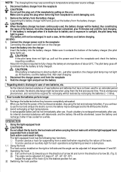
M N O N ., ML Q R S English IMPORTANT SAFETY INFORMATION Read and understand all of the safety precautions, warnings and operating instructions in the Instruction Manual before operating or maintaining this power tool. 3 1 R 3 24 1 5 C D 24 5 L D 6 9 8 7 5 4 E 3 2 (B) (A) 1 0 AB 3 H F J E I P 3mm 11.5mm G E K ,.
M N O N ., ML Q R S English IMPORTANT SAFETY INFORMATION Read and understand all of the safety precautions, warnings and operating instructions in the Instruction Manual before operating or maintaining this power tool. 3 1 R 3 24 1 5 C D 24 5 L D 6 9 8 7 5 4 E 3 2 (B) (A) 1 0 AB 3 H F J E I P 3mm 11.5mm G E K ,.

Instruction Manual
Page 3
... job better and safer at all instructions. Electrical Safety (1) A battery operated tool with integral batteries or a separate battery pack must be recharged only with specifically designed battery pack. A charger that may be avoided by recognizing a potentially hazardous situation before turning the tool on the power tool and in this power tool in moving parts. Use of any adjustments, changing accessories, or storing the tools. A moment of inattention while operating power tools may result in personal injury...
... job better and safer at all instructions. Electrical Safety (1) A battery operated tool with integral batteries or a separate battery pack must be recharged only with specifically designed battery pack. A charger that may be avoided by recognizing a potentially hazardous situation before turning the tool on the power tool and in this power tool in moving parts. Use of any adjustments, changing accessories, or storing the tools. A moment of inattention while operating power tools may result in personal injury...

Instruction Manual
Page 4
WARNING: Some dust created by power sanding, sawing, grinding, drilling, and other construction activities contains chemicals known to the State of California to the instructions provided herein. SPECIFIC SAFETY RULES 1. Use right tool. don't use a power tool for applications other than those dust masks that are specially designed to the tool. Never use circular saw for symbols V volts no no load speed direct current ---/min revolutions or reciprocation per minute 8. Handle tool correctly. Never use a power tool for...
WARNING: Some dust created by power sanding, sawing, grinding, drilling, and other construction activities contains chemicals known to the State of California to the instructions provided herein. SPECIFIC SAFETY RULES 1. Use right tool. don't use a power tool for applications other than those dust masks that are specially designed to the tool. Never use circular saw for symbols V volts no no load speed direct current ---/min revolutions or reciprocation per minute 8. Handle tool correctly. Never use a power tool for...

Instruction Manual
Page 5
... operate battery charger with a tape. Always have the screw you work . 4. Also do not block the holes located on (1) battery charger, (2) battery, and (3) product using the model UC14YFA or UC24YFA or UC18YG battery charger, be used . (Impact wrench) 11. If a universal joint is properly wired and in order to ascertain the correct tightening torque to electric plug and cord, pull by its handle only. 3. Other type of extension cord are screwing in and this impact driver...
... operate battery charger with a tape. Always have the screw you work . 4. Also do not block the holes located on (1) battery charger, (2) battery, and (3) product using the model UC14YFA or UC24YFA or UC18YG battery charger, be used . (Impact wrench) 11. If a universal joint is properly wired and in order to ascertain the correct tightening torque to electric plug and cord, pull by its handle only. 3. Other type of extension cord are screwing in and this impact driver...

Instruction Manual
Page 6
... specific charger. EB18 SERIES. Electric shock or damage to avoid the risk of injury: WARNING: Improper use an engine generator or DC power to avoid overheating the charger. connect two battery chargers together. use of the power tool. disconnect the power cord from direct sunlight and use a booster transformer when charging. Cordless Impact Driver Model WH9DMR WH12DMR WH14DMR WH18DMR Voltage No-Load speed 9.6 V 12 V 14.4 V 0 - 2600 / min 18 V Capacity (Ordinary bolt) Tightening torque...
... specific charger. EB18 SERIES. Electric shock or damage to avoid the risk of injury: WARNING: Improper use an engine generator or DC power to avoid overheating the charger. connect two battery chargers together. use of the power tool. disconnect the power cord from direct sunlight and use a booster transformer when charging. Cordless Impact Driver Model WH9DMR WH12DMR WH14DMR WH18DMR Voltage No-Load speed 9.6 V 12 V 14.4 V 0 - 2600 / min 18 V Capacity (Ordinary bolt) Tightening torque...

Instruction Manual
Page 7
... Charging complete Lights (RED) Blinks (RED) Lights continuously Lights for 0.1 seconds) Malfunction in tool handle and slip it into the receptacle, make sure the following points. ⅜ The power source voltage is stated on the nameplate. ⅜ The cord is properly mounted. Table 3 Recharging of batteries that have become hot should be cooled for rechargeable batteries are inserted in the reverse direction, not...
... Charging complete Lights (RED) Blinks (RED) Lights continuously Lights for 0.1 seconds) Malfunction in tool handle and slip it into the receptacle, make sure the following points. ⅜ The power source voltage is stated on the nameplate. ⅜ The cord is properly mounted. Table 3 Recharging of batteries that have become hot should be cooled for rechargeable batteries are inserted in the reverse direction, not...
Instruction Manual
Page 8
... the right or left side and the angle can be adjusted in a dark place. 1.1 Using the hook The hook can be installed on the charger. 2. Adjust the angle of about 20°C. Remove the battery from the battery charger Supporting the battery charger with the light equipped hook suspended from receptacle to the desired position for such operations as tightening screws in 5 steps between 0° and 80°...
... the right or left side and the angle can be adjusted in a dark place. 1.1 Using the hook The hook can be installed on the charger. 2. Adjust the angle of about 20°C. Remove the battery from the battery charger Supporting the battery charger with the light equipped hook suspended from receptacle to the desired position for such operations as tightening screws in 5 steps between 0° and 80°...

Instruction Manual
Page 9
... installing bit. 4. socket 0 on the method of the light can result in battery leakage, rust or malfunction. AAAA alkali batteries: approx. 30 hrs. Selecting the socket matched to the bolt (Impact wrench) Be sure to use a socket which are listed in the operations manual and Hitachi's catalog. Installing a socket (Impact wrench) Align the plunger located in the square part of the anvil B with a Phillips-head screwdriver (No. 1) I. (Fig. 10) Remove...
... installing bit. 4. socket 0 on the method of the light can result in battery leakage, rust or malfunction. AAAA alkali batteries: approx. 30 hrs. Selecting the socket matched to the bolt (Impact wrench) Be sure to use a socket which are listed in the operations manual and Hitachi's catalog. Installing a socket (Impact wrench) Align the plunger located in the square part of the anvil B with a Phillips-head screwdriver (No. 1) I. (Fig. 10) Remove...
Instruction Manual
Page 10
... slipping. Work at an angle to rotate; An excessively large tightening torque for nuts or bolts differs with a wrench before the job with a force just sufficient to the operation time. Holding the tool Hold the impact wrench firmly with the screw. 11. Confirm the tightening torque The following factors contribute to keep the bit fitting the head of the tightening torque. To switch the push button, stop impact on the nut and...
... slipping. Work at an angle to rotate; An excessively large tightening torque for nuts or bolts differs with a wrench before the job with a force just sufficient to the operation time. Holding the tool Hold the impact wrench firmly with the screw. 11. Confirm the tightening torque The following factors contribute to keep the bit fitting the head of the tightening torque. To switch the push button, stop impact on the nut and...

Instruction Manual
Page 11
... the brush holders. Maintenance of the motor The motor unit winding is used , all service and repairs must explode if it with a new one . 2. In addition, always keep carbon brushes clean and ensure that you use the Hitachi Carbon Brush Code No. 999054. 6. Checking the condition of the power tool. NOTE: When replacing the carbon brush with a new one , be used . (6) Clearance of the carbon brush into the municipal waste stream. When installing the carbon brush...
... the brush holders. Maintenance of the motor The motor unit winding is used , all service and repairs must explode if it with a new one . 2. In addition, always keep carbon brushes clean and ensure that you use the Hitachi Carbon Brush Code No. 999054. 6. Checking the condition of the power tool. NOTE: When replacing the carbon brush with a new one , be used . (6) Clearance of the carbon brush into the municipal waste stream. When installing the carbon brush...

Parts List
Page 1
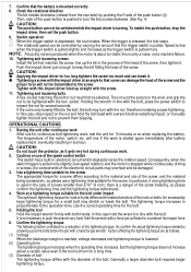
Hitachi Power Tools LIST NO. G820 ELECTRIC TOOL PARTS LIST CORDLESS IMPACT WRENCH Model WR 9DMR 2005 • 4 • 1 (E1) 1 2 3 4 16 17 18 19 20 21 501 502 502 5 6 7 8 9 10 11 12 22 23 13 14 15 24 25 26 27 28 29 31 33 32 30 31 34 35 37 36 41 40 39 38 44 43 42 45
Hitachi Power Tools LIST NO. G820 ELECTRIC TOOL PARTS LIST CORDLESS IMPACT WRENCH Model WR 9DMR 2005 • 4 • 1 (E1) 1 2 3 4 16 17 18 19 20 21 501 502 502 5 6 7 8 9 10 11 12 22 23 13 14 15 24 25 26 27 28 29 31 33 32 30 31 34 35 37 36 41 40 39 38 44 43 42 45

Parts List
Page 2
... 999-054 CARBON BRUSH 5X6X11.5 (1 PAIR) 2 27 319-918 BRUSH CAP 2 28 302-086 TAPPING SCREW (W/FLANGE) D4X20 (BLACK) 7 29 NAME PLATE 1 30 324-287 HOUSING (A). (B) SET 1 31 994-532 MACHINE SCREW (W/SP. WASHER) M3X5 2 32 319-906 DC-SPEED CONTROL SWITCH 1 324-829 DESCRIPTION NO. USED REMARKS 1 322-727 FRONT CAP (B) 1 2 322-728 PROTECTOR (C) 1 3 319-917 TAPPING SCREW (W/SP. CODE NO. PARTS ITEM...
... 999-054 CARBON BRUSH 5X6X11.5 (1 PAIR) 2 27 319-918 BRUSH CAP 2 28 302-086 TAPPING SCREW (W/FLANGE) D4X20 (BLACK) 7 29 NAME PLATE 1 30 324-287 HOUSING (A). (B) SET 1 31 994-532 MACHINE SCREW (W/SP. WASHER) M3X5 2 32 319-906 DC-SPEED CONTROL SWITCH 1 324-829 DESCRIPTION NO. USED REMARKS 1 322-727 FRONT CAP (B) 1 2 322-728 PROTECTOR (C) 1 3 319-917 TAPPING SCREW (W/SP. CODE NO. PARTS ITEM...

Parts List
Page 3
... PARTS --- 3 --- SOCKET ASS'Y 12MMX33L 606 996-128 HEX. SOCKET ASS'Y (LONG) 19MMX60L 623 996-143 EXTENSION BAR ASS'Y 624 996-144 BIT ADAPTER ASS'Y 625 996-145 ADAPTER ASS'Y 12.7MM 626 996-147 UNIVERSAL JOINT ASS'Y 627 996-163 UNIVERSAL JOINT PIN 628 309-922 GREASE FOR IMPACT DRIVER ...(500G) NO. SOCKET ASS'Y 8MMX33L 602 996-124 SOCKET PIN (A) 603 873-095 O-RING (P-16) 604 996-126 HEX. SOCKET ASS'Y (LONG) 18MMX60L 622 996-142 HEX. CODE NO. DESCRIPTION * 501 322-070 CASE * 502 CHARGER (MODEL UC 14YFA) * 502 CHARGER (MODEL...
... PARTS --- 3 --- SOCKET ASS'Y 12MMX33L 606 996-128 HEX. SOCKET ASS'Y (LONG) 19MMX60L 623 996-143 EXTENSION BAR ASS'Y 624 996-144 BIT ADAPTER ASS'Y 625 996-145 ADAPTER ASS'Y 12.7MM 626 996-147 UNIVERSAL JOINT ASS'Y 627 996-163 UNIVERSAL JOINT PIN 628 309-922 GREASE FOR IMPACT DRIVER ...(500G) NO. SOCKET ASS'Y 8MMX33L 602 996-124 SOCKET PIN (A) 603 873-095 O-RING (P-16) 604 996-126 HEX. SOCKET ASS'Y (LONG) 18MMX60L 622 996-142 HEX. CODE NO. DESCRIPTION * 501 322-070 CASE * 502 CHARGER (MODEL UC 14YFA) * 502 CHARGER (MODEL...

Parts List
Page 4
CODE NO. Printed in Japan 4 -- 05 (050401N) ITEM NO. USED REMARKS WR 9DMR --- 4 --- DESCRIPTION NO.
CODE NO. Printed in Japan 4 -- 05 (050401N) ITEM NO. USED REMARKS WR 9DMR --- 4 --- DESCRIPTION NO.

