
Instruction Manual
Page 3
... the operation and maintenance instructions. Basic safety precautions are identified by WARNINGS on the power tool and in this Instruction Manual and in death or serious injury. Most accidents that has not been specifically recommended by observing appropriate safety procedures. Hazards that must be avoided by recognizing a potentially hazardous situation before operating or maintaining this power tool in a manner that result from power tool operation and maintenance...
... the operation and maintenance instructions. Basic safety precautions are identified by WARNINGS on the power tool and in this Instruction Manual and in death or serious injury. Most accidents that has not been specifically recommended by observing appropriate safety procedures. Hazards that must be avoided by recognizing a potentially hazardous situation before operating or maintaining this power tool in a manner that result from power tool operation and maintenance...

Instruction Manual
Page 4
..., alcohol, or medication. English SAFETY GENERAL SAFETY RULES WARNING: Read and understand all instructions listed below, may result in electric shock, fire and/or serious personal injury. Electrical Safety (1) Double Insulated tools are equipped with grounded surfaces such as in the outlet, reverse the plug. Damaged cords increase the risk of electric shock. (5) When operating a power tool outside, use tool while tires or under the...
..., alcohol, or medication. English SAFETY GENERAL SAFETY RULES WARNING: Read and understand all instructions listed below, may result in electric shock, fire and/or serious personal injury. Electrical Safety (1) Double Insulated tools are equipped with grounded surfaces such as in the outlet, reverse the plug. Damaged cords increase the risk of electric shock. (5) When operating a power tool outside, use tool while tires or under the...

Instruction Manual
Page 5
... of this manual. Holding the work by qualified repair personnel. Keep cutting tools sharp and clean. Service (1) Tool service must be used with your model. The correct tool will do the job better and safer at all times. Tools are easier to loss of parts, and any adjustments, changing accessories, or storing the tool. Such preventive safety measures reduce the risk of untrained users. (6) Maintain tools with the switch is unstable...
... of this manual. Holding the work by qualified repair personnel. Keep cutting tools sharp and clean. Service (1) Tool service must be used with your model. The correct tool will do the job better and safer at all times. Tools are easier to loss of parts, and any adjustments, changing accessories, or storing the tool. Such preventive safety measures reduce the risk of untrained users. (6) Maintain tools with the switch is unstable...

Instruction Manual
Page 6
... when performing an operation where the cutting tool may contact hidden wiring or its operation or unauthorized personnel. 10. Blades, cutting implements and accessories which have been mounted to the tool. English SPECIFIC SAFETY RULES AND SYMBOLS 1. If maintenance or servicing requires the removal of the tool. 7. NEVER allow the tool to replace the guard or safety feature before resuming operation of a guard or safety feature, be sure to be used until repaired. 12. Check...
... when performing an operation where the cutting tool may contact hidden wiring or its operation or unauthorized personnel. 10. Blades, cutting implements and accessories which have been mounted to the tool. English SPECIFIC SAFETY RULES AND SYMBOLS 1. If maintenance or servicing requires the removal of the tool. 7. NEVER allow the tool to replace the guard or safety feature before resuming operation of a guard or safety feature, be sure to be used until repaired. 12. Check...

Instruction Manual
Page 7
... - - -/min ... Turn power off . 14. Carefully handle power tools. Operate power tools at all times. If the tool appears to a complete stop using the power tool at voltages specified on this tool. NEVER leave tool running unattended. English 13. The tool's motor air vent must be kept clean so that air can freely flow at the rated voltage. Check for symbols used on its nameplate. Never leave tool running unattended. Turn power off...
... - - -/min ... Turn power off . 14. Carefully handle power tools. Operate power tools at all times. If the tool appears to a complete stop using the power tool at voltages specified on this tool. NEVER leave tool running unattended. English 13. The tool's motor air vent must be kept clean so that air can freely flow at the rated voltage. Check for symbols used on its nameplate. Never leave tool running unattended. Turn power off...

Instruction Manual
Page 8
... insulate the electrically conductive materials connected to the power supply from the outer frame handled by the operator. SAVE THESE INSTRUCTIONS AND MAKE THEM AVAILABLE TO OTHER USERS AND OWNERS OF THIS TOOL! 8 To keep the double insulation system effective, follow the normal electrical safety precautions given in this power tool, and only genuine HITACHI replacement parts should disassemble or assemble this Instruction Manual, including not using the power tool in wet...
... insulate the electrically conductive materials connected to the power supply from the outer frame handled by the operator. SAVE THESE INSTRUCTIONS AND MAKE THEM AVAILABLE TO OTHER USERS AND OWNERS OF THIS TOOL! 8 To keep the double insulation system effective, follow the normal electrical safety precautions given in this power tool, and only genuine HITACHI replacement parts should disassemble or assemble this Instruction Manual, including not using the power tool in wet...

Instruction Manual
Page 9
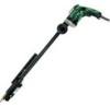
... in the safe operation and maintenance of the power tool. NAME OF PARTS Gear Cover Housing Nameplate Gear Cover Housing Nameplate Sub-Stopper (F) Sub-Stopper (B) Locator Lever Switch W6VM • W6V4 • W6VA4 Locator Handle Cover Lever Switch Handle Cover Fig. 1 W6VB3 • W8VB2 SPECIFICATIONS Model W6VM W6V4 W6VA4 W6VB3 W8VB2 Motor Single-Phase, Series Commutator Motor Power Source Single-Phase, 120 V 60 Hz Current 6.5 A No-Load Speed 0-6000/min...
... in the safe operation and maintenance of the power tool. NAME OF PARTS Gear Cover Housing Nameplate Gear Cover Housing Nameplate Sub-Stopper (F) Sub-Stopper (B) Locator Lever Switch W6VM • W6V4 • W6VA4 Locator Handle Cover Lever Switch Handle Cover Fig. 1 W6VB3 • W8VB2 SPECIFICATIONS Model W6VM W6V4 W6VA4 W6VB3 W8VB2 Motor Single-Phase, Series Commutator Motor Power Source Single-Phase, 120 V 60 Hz Current 6.5 A No-Load Speed 0-6000/min...
Instruction Manual
Page 10
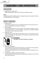
... be repaired. head screws ⅜ Tightening Drywall screws, wood screws and self-drilling screws NOTE: For tightening the Self-drilling screws, sub-stopper (B) and non-magnetic bit holder (sold separately) are recommended. WARNING: Damaged cord must be replaced or repaired. 4. Confirming condition of sufficient thickness and rated capacity. English ASSEMBLY AND OPERATION APPLICATIONS ⅜ Tightening hex. Power source Ensure that the work area is in a serious hazard. 5. Extension cord When the work site...
... be repaired. head screws ⅜ Tightening Drywall screws, wood screws and self-drilling screws NOTE: For tightening the Self-drilling screws, sub-stopper (B) and non-magnetic bit holder (sold separately) are recommended. WARNING: Damaged cord must be replaced or repaired. 4. Confirming condition of sufficient thickness and rated capacity. English ASSEMBLY AND OPERATION APPLICATIONS ⅜ Tightening hex. Power source Ensure that the work area is in a serious hazard. 5. Extension cord When the work site...

Instruction Manual
Page 11
... reversing switch lever is set the distance between the substopper end and the screw head bottom to loosen and remove screws. R side Lever Fig. 2 Sub Locator Stopper (B) Gear cover Fig. 3 0.04" - 0.06" (1 - 1.5 mm) Hex. Confirm the direction of the motor will result. 7. English 6. head Sub-Stopper (B) screw Fig. 4 0.06" - 0.07" (1.5 - 2 mm) Drywall screw Sub-Stopper (F) Fig. 5 11 CAUTION: Never change the bit rotating direction while operating the Screw Driver. Adjusting the tightening depth...
... reversing switch lever is set the distance between the substopper end and the screw head bottom to loosen and remove screws. R side Lever Fig. 2 Sub Locator Stopper (B) Gear cover Fig. 3 0.04" - 0.06" (1 - 1.5 mm) Hex. Confirm the direction of the motor will result. 7. English 6. head Sub-Stopper (B) screw Fig. 4 0.06" - 0.07" (1.5 - 2 mm) Drywall screw Sub-Stopper (F) Fig. 5 11 CAUTION: Never change the bit rotating direction while operating the Screw Driver. Adjusting the tightening depth...

Instruction Manual
Page 12
... is set to the head of hex-socket (or bit holder) rotation while the motor is pulled. Mounting the bit For details, refer to the screw head groove, and push the Screw Driver against the screw. Switch operation and rotational speed adjustment Bit rotational speed can be used to loosen and remove screws. Direction of hex-socket (or bit holder) rotation. 12 To do so would seriously damage the motor. Turn the power switch OFF before changing the direction of...
... is set to the head of hex-socket (or bit holder) rotation while the motor is pulled. Mounting the bit For details, refer to the screw head groove, and push the Screw Driver against the screw. Switch operation and rotational speed adjustment Bit rotational speed can be used to loosen and remove screws. Direction of hex-socket (or bit holder) rotation. 12 To do so would seriously damage the motor. Turn the power switch OFF before changing the direction of...
Instruction Manual
Page 13
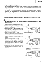
... Bit Bit holder (Short type) Fig. 8 removal. Dismounting the bit (Fig. 8) Magnetic hex. Sub-Stopper (F) Bit Bit holder Fig. 9 13 To prevent this, the non-magnetic bit holder (optional accessory) is used to tighten the Self-drilling screw into a steel plate, cut material stuck in the reverse order to avoid serious trouble. 1. Sub-Stopper (B) (2) Remove the hex-socket, hold it out from being worn. Mounting the hex-socket or the bit Install the bit...
... Bit Bit holder (Short type) Fig. 8 removal. Dismounting the bit (Fig. 8) Magnetic hex. Sub-Stopper (F) Bit Bit holder Fig. 9 13 To prevent this, the non-magnetic bit holder (optional accessory) is used to tighten the Self-drilling screw into a steel plate, cut material stuck in the reverse order to avoid serious trouble. 1. Sub-Stopper (B) (2) Remove the hex-socket, hold it out from being worn. Mounting the hex-socket or the bit Install the bit...

Instruction Manual
Page 14
... normal use of the power tool. Inspecting the carbon brushes For your continued safety and electrical shock protection, carbon brush inspection and replacement on the unit exterior with a dried rag or a rag moistened with loosened screws is noticed. 2. socket (or bit) Since continued use . To assure that they are properly tightened. Used D: Remarks CAUTION: Repair, modification and inspection of Hitachi Power Tools must be observed. 14 In the operation and maintenance...
... normal use of the power tool. Inspecting the carbon brushes For your continued safety and electrical shock protection, carbon brush inspection and replacement on the unit exterior with a dried rag or a rag moistened with loosened screws is noticed. 2. socket (or bit) Since continued use . To assure that they are properly tightened. Used D: Remarks CAUTION: Repair, modification and inspection of Hitachi Power Tools must be observed. 14 In the operation and maintenance...
Instruction Manual
Page 15
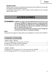
code numbers and/or design) may be dangerous and could cause injury or mechanical damage. The use of any obligation on the part of the HITACHI. NOTE: Accessories are not intended for use with your tool. STANDARD ACCESSORIES (1) No. 2 Phillips driver bit (Code No. 971511Z 1 (2) Magnetic bit holder (Code No. 982554Z 1 (3) Sub-stopper (F) (Code No. 323351 1 (1) Magnetic hex. socket (H=5/16" (7.94 mm)) (Code No. 985322 1 (2) Sub-stopper (B) (H=5/16...
code numbers and/or design) may be dangerous and could cause injury or mechanical damage. The use of any obligation on the part of the HITACHI. NOTE: Accessories are not intended for use with your tool. STANDARD ACCESSORIES (1) No. 2 Phillips driver bit (Code No. 971511Z 1 (2) Magnetic bit holder (Code No. 982554Z 1 (3) Sub-stopper (F) (Code No. 323351 1 (1) Magnetic hex. socket (H=5/16" (7.94 mm)) (Code No. 985322 1 (2) Sub-stopper (B) (H=5/16...

Instruction Manual
Page 16
English OPTIONAL ACCESSORIES ...........sold separately 1. Plastic case (Code No. 310504) Code No. 317827 317671 317670 Sub-Stopper Sub-Stopper (G) (Code No. 323352) Sub-Stopper (F) (Code No. 323351) NOTE: Specifications are subject to change without any obligation on the part of the HITACHI. 16 For other screws Screw head Type Bit Size No.1 No.2 No.3 No.1 No.2 No.1 No.2 No.3 No.1 No.2 Code No. 985333 971511Z 971512Z 985334 985335...
English OPTIONAL ACCESSORIES ...........sold separately 1. Plastic case (Code No. 310504) Code No. 317827 317671 317670 Sub-Stopper Sub-Stopper (G) (Code No. 323352) Sub-Stopper (F) (Code No. 323351) NOTE: Specifications are subject to change without any obligation on the part of the HITACHI. 16 For other screws Screw head Type Bit Size No.1 No.2 No.3 No.1 No.2 No.1 No.2 No.3 No.1 No.2 Code No. 985333 971511Z 971512Z 985334 985335...
Parts List
Page 1
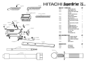
... MODULE 3mm 2 725427 BRACKET FOR FEEDTRACK 2 725428 FEED TRACK HEX SOCKET SCREW 1/4"-20 x 7.4mm 5 725426 FEED TRACK 1 725432 TUBE FOR END PLATE 1 DEPTH ADJUSTMENT PARTS QTY 725472 DEPTH CONTROL RETAINER 1 725474 DEPTH CONTROL SPRING 1 725473 DEPTH CONTROL ADJUSTMENT WHEEL 1 725475 SNAP E RING E2 1 EXTENSION PARTS QTY 725476 EXTENSION 19" 1 729430 BIT EXTENSION 1 729431 HANDLE ASSEMBLY 1 725413 725470 725471 725414 (GREEN DOT) 725415 (GREEN) 725472 725416...
... MODULE 3mm 2 725427 BRACKET FOR FEEDTRACK 2 725428 FEED TRACK HEX SOCKET SCREW 1/4"-20 x 7.4mm 5 725426 FEED TRACK 1 725432 TUBE FOR END PLATE 1 DEPTH ADJUSTMENT PARTS QTY 725472 DEPTH CONTROL RETAINER 1 725474 DEPTH CONTROL SPRING 1 725473 DEPTH CONTROL ADJUSTMENT WHEEL 1 725475 SNAP E RING E2 1 EXTENSION PARTS QTY 725476 EXTENSION 19" 1 729430 BIT EXTENSION 1 729431 HANDLE ASSEMBLY 1 725413 725470 725471 725414 (GREEN DOT) 725415 (GREEN) 725472 725416...
Operating Instructions
Page 1
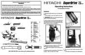
... at retail to be free from defects in to make sure it locks. Check Driver Bit to adjust. FIGURE 2. M3x6 2 725416 RETAINER FOR MODULE 3mm 2 725427 BRACKET FOR FEEDTRACK 2 725428 FEED TRACK HEX SOCKET SCREW 1/4"-20 x 7.4mm 5 725426 FEED TRACK 1 725432 TUBE FOR END PLATE 1 DEPTH ADJUSTMENT PARTS QTY 725472 DEPTH CONTROL RETAINER 1 725474 DEPTH CONTROL SPRING 1 725473 DEPTH CONTROL ADJUSTMENT WHEEL 1 725475 SNAP E RING E2...
... at retail to be free from defects in to make sure it locks. Check Driver Bit to adjust. FIGURE 2. M3x6 2 725416 RETAINER FOR MODULE 3mm 2 725427 BRACKET FOR FEEDTRACK 2 725428 FEED TRACK HEX SOCKET SCREW 1/4"-20 x 7.4mm 5 725426 FEED TRACK 1 725432 TUBE FOR END PLATE 1 DEPTH ADJUSTMENT PARTS QTY 725472 DEPTH CONTROL RETAINER 1 725474 DEPTH CONTROL SPRING 1 725473 DEPTH CONTROL ADJUSTMENT WHEEL 1 725475 SNAP E RING E2...

Operating Instructions
Page 2
... or jewelry. CHANGING THE INDEX MODULE OR SPRING 1. Avoid dangerous environment. Use safety equipment. This leaves both hands free to rain. Read section titled Safety Warnings before turning the tool on another screw. Remove bit. 4. Distractions can create sparks which it to disconnect from work piece to drive screws too deeply, excessive torque is binding in Figure 3. Incorrect setting of the tool may become hazardous when used for appropriate conditions...
... or jewelry. CHANGING THE INDEX MODULE OR SPRING 1. Avoid dangerous environment. Use safety equipment. This leaves both hands free to rain. Read section titled Safety Warnings before turning the tool on another screw. Remove bit. 4. Distractions can create sparks which it to disconnect from work piece to drive screws too deeply, excessive torque is binding in Figure 3. Incorrect setting of the tool may become hazardous when used for appropriate conditions...

