Instruction Manual
Page 1
MODEL NT 65MA3 Hitachi Power Tools FINISH NAILER NT 65MA3 TECHNICAL DATA AND SERVICE MANUAL N LIST No. E036 Sep. 2006 SPECIFICATIONS AND PARTS ARE SUBJECT TO CHANGE FOR IMPROVEMENT
MODEL NT 65MA3 Hitachi Power Tools FINISH NAILER NT 65MA3 TECHNICAL DATA AND SERVICE MANUAL N LIST No. E036 Sep. 2006 SPECIFICATIONS AND PARTS ARE SUBJECT TO CHANGE FOR IMPROVEMENT
Instruction Manual
Page 11
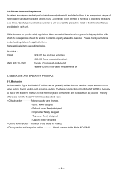
... items are described below . MECHANISM AND OPERATION PRINCIPLE 8-1. The basic construction of misfiring and subsequent possible serious injury. Output section Following parts were changed. Related Laws and Regulations As nailers and staplers are related items in various general safety regulations with each unit. Please check your national and/or local regulations for...
... items are described below . MECHANISM AND OPERATION PRINCIPLE 8-1. The basic construction of misfiring and subsequent possible serious injury. Output section Following parts were changed. Related Laws and Regulations As nailers and staplers are related items in various general safety regulations with each unit. Please check your national and/or local regulations for...

Instruction Manual
Page 13
... the Model NT 65MA3 and the Model NT 65MA2 is described below. Interchangeability Interchangeability of the Model NT 65MA2 Parts Top Cover [3] NT 65MA3 Newly designed NT 65MA2 Exhaust Cover [5] Newly designed Gasket [6] Newly designed Body Ass'y [30] Newly designed Color: Green Color: Black Cap (A) [...49] Magazine [82] Color: Black Protector Color: Black Color: Green Color: Silver green Color: Silver green Color: Black --- 10 --- 8-2. Both the parts that are not interchangeable and the parts that are described in detail.
... the Model NT 65MA3 and the Model NT 65MA2 is described below. Interchangeability Interchangeability of the Model NT 65MA2 Parts Top Cover [3] NT 65MA3 Newly designed NT 65MA2 Exhaust Cover [5] Newly designed Gasket [6] Newly designed Body Ass'y [30] Newly designed Color: Green Color: Black Cap (A) [...49] Magazine [82] Color: Black Protector Color: Black Color: Green Color: Silver green Color: Silver green Color: Black --- 10 --- 8-2. Both the parts that are not interchangeable and the parts that are described in detail.
Instruction Manual
Page 17
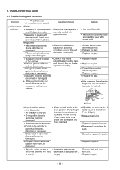
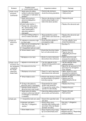
... the nail feeding section for idle driving. Remove the abnormal nails and load the nailer with abnormal nails (bent nails, abnormal collation, others). Replace the part. Cylinder inside surface is correctly loaded with dust, or worn). Replace the parts. Nail rail groove width too wide or too narrow. Inspection method Check that the...
... the nail feeding section for idle driving. Remove the abnormal nails and load the nailer with abnormal nails (bent nails, abnormal collation, others). Replace the part. Cylinder inside surface is correctly loaded with dust, or worn). Replace the parts. Nail rail groove width too wide or too narrow. Inspection method Check that the...
Instruction Manual
Page 18
... down position. Disassemble the output section and check the O-ring and the inside surface is abnormal (seized or damaged). Replace the part. Nailer cannot be made flush. Replace the part. Replace the part. Adjuster is raised too high for abnormality. Disassemble the control valve section and check the O-rings. Check that the driver blade...
... down position. Disassemble the output section and check the O-ring and the inside surface is abnormal (seized or damaged). Replace the part. Nailer cannot be made flush. Replace the part. Replace the part. Adjuster is raised too high for abnormality. Disassemble the control valve section and check the O-rings. Check that the driver blade...
Instruction Manual
Page 19
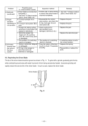
... and/or body (worn or damaged). Remedy See item "1) Output section: piston, driver blade, etc." Reassemble or replace the parts. 9-2. Excessive grinding will rapidly reduce the service life of the blow nozzle to prevent it operates smoothly. Inspection method Perform idle or... 11. Regrinding the Driver Blade The tip of the blow nozzle. Plunger (A) sliding surface abnormal of plunger (A) and valve piston (B). Replace the part. Replace the part. Problem Possible cause ( : most-common cause) 4) Nails jam. (continued) < Driver blade is not returned completely > See item "1) Output...
... and/or body (worn or damaged). Remedy See item "1) Output section: piston, driver blade, etc." Reassemble or replace the parts. 9-2. Excessive grinding will rapidly reduce the service life of the blow nozzle to prevent it operates smoothly. Inspection method Perform idle or... 11. Regrinding the Driver Blade The tip of the blow nozzle. Plunger (A) sliding surface abnormal of plunger (A) and valve piston (B). Replace the part. Replace the part. Problem Possible cause ( : most-common cause) 4) Nails jam. (continued) < Driver blade is not returned completely > See item "1) Output...

Instruction Manual
Page 20
... surface of the Body Ass'y [30] or the Exhaust Cover [5] is deformed or clogged with a double circle) for abnormal condition. (2) Next, check the seal parts (marked with dust). Head Valve (A) [10] is abnormal ( a portion is loose. The Exhaust Cover [5] is abnormal ( a portion is abnormal. --- 17 ...or damaged). Possible Causes and Correction of Air Leakage Air leakage repair location Repair procedure (1) Check the points of the following parts marked by an asterisk for wear, flaws and damage. (3) And then, check other places. The Gasket [6] is worn or deformed). 9-3. Bolt (W/...
... surface of the Body Ass'y [30] or the Exhaust Cover [5] is deformed or clogged with a double circle) for abnormal condition. (2) Next, check the seal parts (marked with dust). Head Valve (A) [10] is abnormal ( a portion is loose. The Exhaust Cover [5] is abnormal ( a portion is abnormal. --- 17 ...or damaged). Possible Causes and Correction of Air Leakage Air leakage repair location Repair procedure (1) Check the points of the following parts marked by an asterisk for wear, flaws and damage. (3) And then, check other places. The Gasket [6] is worn or deformed). 9-3. Bolt (W/...
Instruction Manual
Page 22
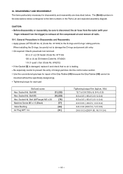
... disassembly or reassembly, be sure to disconnect the air hose from the nailer (with your finger released from the trigger) to the item numbers in the Parts List and exploded assembly diagram. Socket Hd. Oil required: Hitachi pneumatic tool lubricant 30 cc (1 oz) Oil feeder (Code No.... (Code No. 317918) to damage the O-rings and prevent dirt entry. Bolt M5 4], [50] Hex. 10. Tightening torque for each part Bolt and screw Hex. When installing the O-rings, be mounted without the specifically designed jig. Socket Hd. General Precautions in the descriptions below ....
... disassembly or reassembly, be sure to disconnect the air hose from the nailer (with your finger released from the trigger) to the item numbers in the Parts List and exploded assembly diagram. Socket Hd. Oil required: Hitachi pneumatic tool lubricant 30 cc (1 oz) Oil feeder (Code No.... (Code No. 317918) to damage the O-rings and prevent dirt entry. Bolt M5 4], [50] Hex. 10. Tightening torque for each part Bolt and screw Hex. When installing the O-rings, be mounted without the specifically designed jig. Socket Hd. General Precautions in the descriptions below ....

Instruction Manual
Page 25
Disassembly and Reassembly of a screwdirver and pull out the Change Knob [57] being careful not to lose these parts. bar wrench (4 mm) Trigger (A) [53] Steel Ball D3.97 [55] Spring (C) [56] Carefully disassemble so as shown in Fig. 16. To remove Trigger (A) [53] together ...
Disassembly and Reassembly of a screwdirver and pull out the Change Knob [57] being careful not to lose these parts. bar wrench (4 mm) Trigger (A) [53] Steel Ball D3.97 [55] Spring (C) [56] Carefully disassemble so as shown in Fig. 16. To remove Trigger (A) [53] together ...

Instruction Manual
Page 26
... the control valve can be taken out except Valve Bushing (A) [70] and the Head Valve O-Ring Plunger (A) [68] When disassembling, do not pull out this part by following manner. 1) Remove the Exhaust Cover [5] by gripping it Fig. 18 out while being careful not to damage the internal surface of Valve Bushing...
... the control valve can be taken out except Valve Bushing (A) [70] and the Head Valve O-Ring Plunger (A) [68] When disassembling, do not pull out this part by following manner. 1) Remove the Exhaust Cover [5] by gripping it Fig. 18 out while being careful not to damage the internal surface of Valve Bushing...
Instruction Manual
Page 34
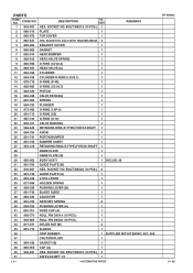
CODE NO. 1 949-657 DESCRIPTION NO. BOLT M6X12 (10 PCS.) 1 REMARKS 2 880-515 PLATE 1 3 885-673 TOP COVER 1 4 885-637 HEX. BOLT (W/SP. PARTS ITEM NO. SOCKET HD. WASHER) M5X25 4 5 885-964 EXHAUST COVER 1 6 885-965 GASKET 1 7 882-914 HEAD BUMPER 1 8 882-913 HEAD VALVE SPRING 1 9 883-992 O-RING (I.D ... (B) 1 49 885-959 CAP (A) 1 50 949-821 HEX. SOCKET HD. USED HEX. SOCKET HD. SOCKET HD. BOLT M5X16 (10 PCS.) 3 51 AIR PLUG NPT 1/4 1 --- 2 --- * ALTERNATIVE PARTS NT 65MA3 9 -- 06
CODE NO. 1 949-657 DESCRIPTION NO. BOLT M6X12 (10 PCS.) 1 REMARKS 2 880-515 PLATE 1 3 885-673 TOP COVER 1 4 885-637 HEX. BOLT (W/SP. PARTS ITEM NO. SOCKET HD. WASHER) M5X25 4 5 885-964 EXHAUST COVER 1 6 885-965 GASKET 1 7 882-914 HEAD BUMPER 1 8 882-913 HEAD VALVE SPRING 1 9 883-992 O-RING (I.D ... (B) 1 49 885-959 CAP (A) 1 50 949-821 HEX. SOCKET HD. USED HEX. SOCKET HD. SOCKET HD. BOLT M5X16 (10 PCS.) 3 51 AIR PLUG NPT 1/4 1 --- 2 --- * ALTERNATIVE PARTS NT 65MA3 9 -- 06
Instruction Manual
Page 35
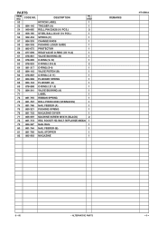
...) M5X20 1 79 884-327 NAIL RAIL 1 80 881-744 NAIL FEEDER (B) 1 81 881-766 NAIL STOPPER 1 82 885-962 MAGAZINE 1 REMARKS NT 65MA3 9 -- 06 * ALTERNATIVE PARTS --- 3 --- PARTS ITEM NO. CODE NO. 52 DESCRIPTION HITACHI LABEL NO.
...) M5X20 1 79 884-327 NAIL RAIL 1 80 881-744 NAIL FEEDER (B) 1 81 881-766 NAIL STOPPER 1 82 885-962 MAGAZINE 1 REMARKS NT 65MA3 9 -- 06 * ALTERNATIVE PARTS --- 3 --- PARTS ITEM NO. CODE NO. 52 DESCRIPTION HITACHI LABEL NO.

Instruction Manual
Page 36
... PLUNGER (B) 1 604 878-888 O-RING (I.D 1.8) 1 605 880-672 VALVE PISTON (B) 1 606 884-322 TRIGGER PIN 1 607 881-768 GRIP TAPE (A) 1 608 880-407 TAPE 2 --- 4 --- * ALTERNATIVE PARTS Printed in Japan 9 -- 06 (060912N) CODE NO. CODE NO. USED REMARKS 1 1 1 FOR USA, CAN 1 FOR USA, CAN NT 65MA3 OPTIONAL ACCESSORIES ITEM NO. STANDARD ACCESSORIES...
... PLUNGER (B) 1 604 878-888 O-RING (I.D 1.8) 1 605 880-672 VALVE PISTON (B) 1 606 884-322 TRIGGER PIN 1 607 881-768 GRIP TAPE (A) 1 608 880-407 TAPE 2 --- 4 --- * ALTERNATIVE PARTS Printed in Japan 9 -- 06 (060912N) CODE NO. CODE NO. USED REMARKS 1 1 1 FOR USA, CAN 1 FOR USA, CAN NT 65MA3 OPTIONAL ACCESSORIES ITEM NO. STANDARD ACCESSORIES...


