Instruction Manual
Page 1
E036 Sep. 2006 SPECIFICATIONS AND PARTS ARE SUBJECT TO CHANGE FOR IMPROVEMENT MODEL NT 65MA3 Hitachi Power Tools FINISH NAILER NT 65MA3 TECHNICAL DATA AND SERVICE MANUAL N LIST No.
E036 Sep. 2006 SPECIFICATIONS AND PARTS ARE SUBJECT TO CHANGE FOR IMPROVEMENT MODEL NT 65MA3 Hitachi Power Tools FINISH NAILER NT 65MA3 TECHNICAL DATA AND SERVICE MANUAL N LIST No.
Instruction Manual
Page 3
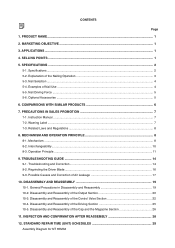
... the Driver Blade ...16 9-3. Possible Causes and Correction of the Nailing Operation 3 5-3. DISASSEMBLY AND REASSEMBLY 19 10-1. Explanation of Air Leakage 17 10. SPECIFICATIONS ...2 5-1. COMPARISONS WITH SIMILAR PRODUCTS 6 7. Operation Principle ...11 9. General Precautions in Disassembly and Reassembly 19 10-2. Specifications ...2 5-2. Nail Selection ...4 5-4. Examples of Nail Use ...4 5-5. CONTENTS Page 1. PRODUCT NAME ...1 2. SELLING POINTS ...1 5. Warning Label ...7 7-3. Mechanism ...8 8-2. TROUBLESHOOTING GUIDE ...14 9-1. STANDARD REPAIR TIME...
... the Driver Blade ...16 9-3. Possible Causes and Correction of the Nailing Operation 3 5-3. DISASSEMBLY AND REASSEMBLY 19 10-1. Explanation of Air Leakage 17 10. SPECIFICATIONS ...2 5-1. COMPARISONS WITH SIMILAR PRODUCTS 6 7. Operation Principle ...11 9. General Precautions in Disassembly and Reassembly 19 10-2. Specifications ...2 5-2. Nail Selection ...4 5-4. Examples of Nail Use ...4 5-5. CONTENTS Page 1. PRODUCT NAME ...1 2. SELLING POINTS ...1 5. Warning Label ...7 7-3. Mechanism ...8 8-2. TROUBLESHOOTING GUIDE ...14 9-1. STANDARD REPAIR TIME...
Instruction Manual
Page 4
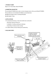
... direction easily changeable Capable of cleaning chips and sawdust thanks to the blow nozzle Grip rubber Simple drivedepth adjusting mechanism Easy-to the Model NR 90AD Light weight (1.9 kg) 3. PRODUCT NAME Hitachi 2-1/2" Finish Nailer, Model NT 65MA3 2. APPLICATIONS For manufactured housing, on-site and mobile home construction: Mounting of light and heavy trim Installation of molding, paneling and stairways Assembling of the current Model...
... direction easily changeable Capable of cleaning chips and sawdust thanks to the blow nozzle Grip rubber Simple drivedepth adjusting mechanism Easy-to the Model NR 90AD Light weight (1.9 kg) 3. PRODUCT NAME Hitachi 2-1/2" Finish Nailer, Model NT 65MA3 2. APPLICATIONS For manufactured housing, on-site and mobile home construction: Mounting of light and heavy trim Installation of molding, paneling and stairways Assembling of the current Model...
Instruction Manual
Page 5
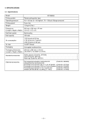
Specifications Model Driving system Operating pressure Driving speed Weight NT 65MA3 Reciprocating piston type 4.9 --- 8.3 bar (5 --- 8.5 kgf/cm2, 70 --- 120 psi) (Gauge pressure) 3 pcs./sec 1.9 kg (4.2 lbs.) Dimensions 343 mm x 305 mm x 76 mm (Length x Height x Width) (13-1/2" x 12" x 3") Nail feed system Nail capacity Spiral spring 100 nails Air consumption Air inlet Packaging 1.20 ltr/cycle at 6.9 bar (1.20 ltr/cycle at 7 kgf/cm2) (.042 ft3/cycle at 100...
Specifications Model Driving system Operating pressure Driving speed Weight NT 65MA3 Reciprocating piston type 4.9 --- 8.3 bar (5 --- 8.5 kgf/cm2, 70 --- 120 psi) (Gauge pressure) 3 pcs./sec 1.9 kg (4.2 lbs.) Dimensions 343 mm x 305 mm x 76 mm (Length x Height x Width) (13-1/2" x 12" x 3") Nail feed system Nail capacity Spiral spring 100 nails Air consumption Air inlet Packaging 1.20 ltr/cycle at 6.9 bar (1.20 ltr/cycle at 7 kgf/cm2) (.042 ft3/cycle at 100...
Instruction Manual
Page 6
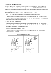
... a nailing operation switching device at the valve section as shown in the figures below. After nailing once, nailing will be performed. next, pull the trigger to continue driving nails. Explanation of the Nailing Operation To meet the requirements of "ANSI SNT-101-2002", the Model NT 65MA3 is released and pressed again. SINGLE ACTUATION MECHANISM (SINGLE SEQUENTIAL ACTUATION MECHANISM): First, press the pushing lever...
... a nailing operation switching device at the valve section as shown in the figures below. After nailing once, nailing will be performed. next, pull the trigger to continue driving nails. Explanation of the Nailing Operation To meet the requirements of "ANSI SNT-101-2002", the Model NT 65MA3 is released and pressed again. SINGLE ACTUATION MECHANISM (SINGLE SEQUENTIAL ACTUATION MECHANISM): First, press the pushing lever...

Instruction Manual
Page 7
... 5-2 for installing finish materials, or molding as specified in circles A and B. Nail Selection The Model NT 65MA3 utilizes small-head, T-shaped nails (finish nails) collated by tapes. CAUTION: Ensure that nails are as shown in Fig. 2. Examples of Nail Use A: Crown molding Fig. 1 Dimensions of nails B: Base molding Examples of molding --- 4 --- 5-3. Typical mounting methods are shown below. Other nails will cause clogging of nails and subsequent damage to the nailer. 15-gauge finish nail (collating angle 34...
... 5-2 for installing finish materials, or molding as specified in circles A and B. Nail Selection The Model NT 65MA3 utilizes small-head, T-shaped nails (finish nails) collated by tapes. CAUTION: Ensure that nails are as shown in Fig. 2. Examples of Nail Use A: Crown molding Fig. 1 Dimensions of nails B: Base molding Examples of molding --- 4 --- 5-3. Typical mounting methods are shown below. Other nails will cause clogging of nails and subsequent damage to the nailer. 15-gauge finish nail (collating angle 34...
Instruction Manual
Page 8
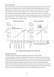
.... Nail Driving Force Figure 3 shows by type of wood. Figure 3 should be driven below the wood surface. Optional Accessories Full sequential actuation mechanism kit (sequential trip mechanism kit) (Code No. 884320) A full sequential actuation mechanism kit (sequential trip mechanism kit) is driven when pulling the trigger first and then pressing the pushing lever against a workpiece and then pulling the trigger (single-shot operation...
.... Nail Driving Force Figure 3 shows by type of wood. Figure 3 should be driven below the wood surface. Optional Accessories Full sequential actuation mechanism kit (sequential trip mechanism kit) (Code No. 884320) A full sequential actuation mechanism kit (sequential trip mechanism kit) is driven when pulling the trigger first and then pressing the pushing lever against a workpiece and then pulling the trigger (single-shot operation...
Instruction Manual
Page 9
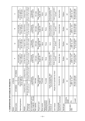
... None Nailing operation switching device Provided None None None None Direction change of exhaust air Easily changeable 360û by turning by hand Easily changeable 360û by turning by hand None Easily changeable 360û Easily changeable 360û by turning by hand by turning by hand Jam-release Single-touch operation by hand Single-touch operation Single-touch operation Single-touch operation Single-touch operation by hand by hand by hand by hand Driving depth adjustment...
... None Nailing operation switching device Provided None None None None Direction change of exhaust air Easily changeable 360û by turning by hand Easily changeable 360û by turning by hand None Easily changeable 360û Easily changeable 360û by turning by hand by turning by hand Jam-release Single-touch operation by hand Single-touch operation Single-touch operation Single-touch operation Single-touch operation by hand by hand by hand by hand Driving depth adjustment...
Instruction Manual
Page 10
... the contents of the Instruction Manual, and fully understands the meaning of the precautions listed on the Warning Label attached to enhance the safe, efficient use of the Model NT 65MA3 Nailer by the customer. Refer to use . Carefully ensure that the full sequential actuation mechanism kit (sequential trip mechanism kit) which lists basic safety precautions in the Instruction Manual to each step...
... the contents of the Instruction Manual, and fully understands the meaning of the precautions listed on the Warning Label attached to enhance the safe, efficient use of the Model NT 65MA3 Nailer by the customer. Refer to use . Carefully ensure that the full sequential actuation mechanism kit (sequential trip mechanism kit) which lists basic safety precautions in the Instruction Manual to each step...
Instruction Manual
Page 11
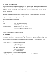
... that of the Model NT 65MA2 and the interchangeable components are used as much as that the customer is fully aware of the precautions listed in order to properly advise the customer. The U.S.A.: OSHA ANSI SNT-101-2002 1926.102 Eye and face protection 1926.302 Power-operated hand tools Portable, Compressed-Air-Actuated, Fastener Driving Tools-Safety Requirements for applicable items...
... that of the Model NT 65MA2 and the interchangeable components are used as much as that the customer is fully aware of the precautions listed in order to properly advise the customer. The U.S.A.: OSHA ANSI SNT-101-2002 1926.102 Eye and face protection 1926.302 Power-operated hand tools Portable, Compressed-Air-Actuated, Fastener Driving Tools-Safety Requirements for applicable items...

Instruction Manual
Page 16
... is released, Plunger (A) Valve piston lower chamber Plate Pushing Lever (B) [36] Switching device (Change Knob [57]) (upward position) [68] returns (lowers) completely as shown in Fig. 6. Compressed air then flows into the valve piston lower chamber, and Valve Piston (B) [65] remains in the lowered position. Contact actuation mechanism (Switching device: downward position): 1) Immediately after each nailing operation, the structural mechanism prevents the next nailing operation...
... is released, Plunger (A) Valve piston lower chamber Plate Pushing Lever (B) [36] Switching device (Change Knob [57]) (upward position) [68] returns (lowers) completely as shown in Fig. 6. Compressed air then flows into the valve piston lower chamber, and Valve Piston (B) [65] remains in the lowered position. Contact actuation mechanism (Switching device: downward position): 1) Immediately after each nailing operation, the structural mechanism prevents the next nailing operation...
Instruction Manual
Page 17
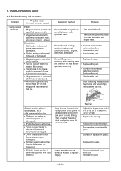
... operates smoothly. Driver blade is abnormal (fatigued or damaged). Replace the part. Magazine is abnormal (removed, deformed or damaged). Magazine cover is abnormal (packed with dust, or worn). Replace the part. Keep the nail feeder in the cylinder is loaded with proper nails. Cylinder inside surface is abnormal (deformed or damaged). Correct the burred or deformed portion. TROUBLESHOOTING GUIDE 9-1. Then, check if the driver blade and guide plate...
... operates smoothly. Driver blade is abnormal (fatigued or damaged). Replace the part. Magazine is abnormal (removed, deformed or damaged). Magazine cover is abnormal (packed with dust, or worn). Replace the part. Keep the nail feeder in the cylinder is loaded with proper nails. Cylinder inside surface is abnormal (deformed or damaged). Correct the burred or deformed portion. TROUBLESHOOTING GUIDE 9-1. Then, check if the driver blade and guide plate...
Instruction Manual
Page 18
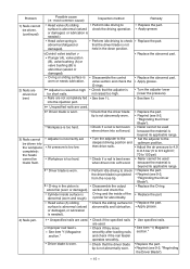
... projected from the nose tip. Perform idle driving to 120 psi) Nailer cannot be used . < Improper nail feed > See item "1) Magazine section." Check if a nail is too low. Regrind (see 9-2, "Regrinding the Driver Blade"). --- 15 --- Air pressure is bent even when driven into the injection port. Driver blade is needed .) Head valve spring is beyond its applicable range. Head valve (A) sliding surface is abnormal (seized or damaged, or...
... projected from the nose tip. Perform idle driving to 120 psi) Nailer cannot be used . < Improper nail feed > See item "1) Magazine section." Check if a nail is too low. Regrind (see 9-2, "Regrinding the Driver Blade"). --- 15 --- Air pressure is bent even when driven into the injection port. Driver blade is needed .) Head valve spring is beyond its applicable range. Head valve (A) sliding surface is abnormal (seized or damaged, or...
Instruction Manual
Page 19
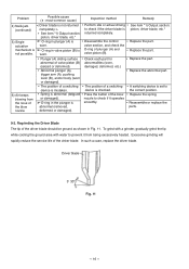
... driving to prevent it operates smoothly. Press the button of the driver blade. Replace the part. Excessive grinding will rapidly reduce the service life of the blow nozzle to the correct position. In such a case, replace the driver blade. Abnormal plunger (A), trigger arm (A), pushing lever (B), and/or body (worn or damaged). Remedy See item "1) Output section: piston, driver blade, etc." Replace the part. Regrinding the Driver Blade The tip of a switching...
... driving to prevent it operates smoothly. Press the button of the driver blade. Replace the part. Excessive grinding will rapidly reduce the service life of the blow nozzle to the correct position. In such a case, replace the driver blade. Abnormal plunger (A), trigger arm (A), pushing lever (B), and/or body (worn or damaged). Remedy See item "1) Output section: piston, driver blade, etc." Replace the part. Regrinding the Driver Blade The tip of a switching...
Instruction Manual
Page 22
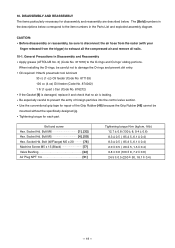
General Precautions in the Parts List and exploded assembly diagram. Use the conventional grip tape for repair of foreign particles into the control valve section. Bolt (W/Flange) M5 x 20 78] Machine Screw M5 x 15 (Black 77] Valve Bushing [22 Air Plug NPT 1/4 [51 Tightening torque N•m (kgf•cm, ft-lb) 12.7 0.8 (130 8, 9.4 0.6) 8.3 0.5 ( 85 5, 6.1 0.4) 8.3 0.5 ( 85 5, 6.1 0.4) 2.0 0.5 ( 20 5, 1.5 0.4) 9.8 0.8 (100 8, 7.2 0.6) 24.5 0.5 (250 50, 18.1 0.4) --- 19 --- DISASSEMBLY...
General Precautions in the Parts List and exploded assembly diagram. Use the conventional grip tape for repair of foreign particles into the control valve section. Bolt (W/Flange) M5 x 20 78] Machine Screw M5 x 15 (Black 77] Valve Bushing [22 Air Plug NPT 1/4 [51 Tightening torque N•m (kgf•cm, ft-lb) 12.7 0.8 (130 8, 9.4 0.6) 8.3 0.5 ( 85 5, 6.1 0.4) 8.3 0.5 ( 85 5, 6.1 0.4) 2.0 0.5 ( 20 5, 1.5 0.4) 9.8 0.8 (100 8, 7.2 0.6) 24.5 0.5 (250 50, 18.1 0.4) --- 19 --- DISASSEMBLY...

Instruction Manual
Page 23
... Fig. 12.) Hex. Socket Hd. Washer) M5 x 25 [4] with the Bumper Sheet [26] assembled) can now be removed. Bolt (W/Sp. Bolts (W/Sp. Remove the Hex. bar wrenches (5 mm and 4 mm) (a) Disassembly Remove the four Hex. Bolt M6 x 12 [1] with a hex. Head Valve (A) [10] Cylinder [11] Cylinder O-Ring (I.D 63.1) [12] O-Ring (P-46) [13] O-Ring (I .D 20.8) [9] [Tools required] Hex. 10-2. Disassembly and...
... Fig. 12.) Hex. Socket Hd. Washer) M5 x 25 [4] with the Bumper Sheet [26] assembled) can now be removed. Bolt (W/Sp. Bolts (W/Sp. Remove the Hex. bar wrenches (5 mm and 4 mm) (a) Disassembly Remove the four Hex. Bolt M6 x 12 [1] with a hex. Head Valve (A) [10] Cylinder [11] Cylinder O-Ring (I.D 63.1) [12] O-Ring (P-46) [13] O-Ring (I .D 20.8) [9] [Tools required] Hex. 10-2. Disassembly and...

Instruction Manual
Page 24
...to the Plunger [18] then press the Knob [24] against the Retaining Ring (E-type) for D4 Shaft [23] Exhaust Cover [5] Valve Bushing [22] Plunger [18] Spring [17] Valve Packing [16] Fig. 14 Disassembly and reassembly of Head Valve (A) [10] (Fig. 13). Apply ...Knob [24] Retaining Ring (E-type) for D4 Shaft [23] to mount it to the sliding surface a of the Exhaust Cover [5] and Head Valve (A) [10] and charge about 0.5 g (.018 oz) of the Valve Bushing [22], Plunger [18], etc. (See Fig. 14.) [Tools required] Socket wrench (14 mm) Flat-blade head screwdriver (a) Disassembly Remove the Valve...
...to the Plunger [18] then press the Knob [24] against the Retaining Ring (E-type) for D4 Shaft [23] Exhaust Cover [5] Valve Bushing [22] Plunger [18] Spring [17] Valve Packing [16] Fig. 14 Disassembly and reassembly of Head Valve (A) [10] (Fig. 13). Apply ...Knob [24] Retaining Ring (E-type) for D4 Shaft [23] to mount it to the sliding surface a of the Exhaust Cover [5] and Head Valve (A) [10] and charge about 0.5 g (.018 oz) of the Valve Bushing [22], Plunger [18], etc. (See Fig. 14.) [Tools required] Socket wrench (14 mm) Flat-blade head screwdriver (a) Disassembly Remove the Valve...

Instruction Manual
Page 25
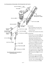
...] O-ring (I.D 11) [66] Plunger Spring [67] Plunger (A) [68] O-ring (I.D 1.8) [69] Valve Bushing (A) [70] Change Knob [57] Head Valve O-ring (I.D 16.8) [60] (a) Disassembly Remove the Retaining Ring (E-type) for D6 Shaft [27] Roll Pin D3 x 28 [54] [Tools required] Flat-blade screwdriver Roll pin puller (3 mm (.118") dia.) Hex. Then Trigger (A) [53] can be removed. Disassembly and Reassembly of the Control Valve Section (See Fig. 15.) Retaining...
...] O-ring (I.D 11) [66] Plunger Spring [67] Plunger (A) [68] O-ring (I.D 1.8) [69] Valve Bushing (A) [70] Change Knob [57] Head Valve O-ring (I.D 16.8) [60] (a) Disassembly Remove the Retaining Ring (E-type) for D6 Shaft [27] Roll Pin D3 x 28 [54] [Tools required] Flat-blade screwdriver Roll pin puller (3 mm (.118") dia.) Hex. Then Trigger (A) [53] can be removed. Disassembly and Reassembly of the Control Valve Section (See Fig. 15.) Retaining...
Instruction Manual
Page 28
... in the Instruction Manual) so that Roll Pin D3 x 20 [43] Adjuster [38] Pushing Lever (A) [40] can be removed from the Adjuster [38] with small tip Pushing Lever (B) [36] (a) Disassembly Continuously turn the Adjuster [38] in the direction in which the nail is raised when Lock Lever [34] adjusting the driving depth (refer to lose them. Bolt (W/Flange) M5 x 20 [78] Roll Pin D3 x 28 [54] Blade Guide [37] Guide Plate (B) [31...
... in the Instruction Manual) so that Roll Pin D3 x 20 [43] Adjuster [38] Pushing Lever (A) [40] can be removed from the Adjuster [38] with small tip Pushing Lever (B) [36] (a) Disassembly Continuously turn the Adjuster [38] in the direction in which the nail is raised when Lock Lever [34] adjusting the driving depth (refer to lose them. Bolt (W/Flange) M5 x 20 [78] Roll Pin D3 x 28 [54] Blade Guide [37] Guide Plate (B) [31...
Instruction Manual
Page 31
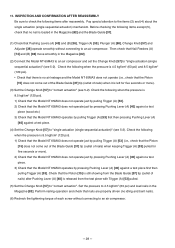
... pressure is loaded in the Magazine [82]. (2) Connect the Model NT 65MA3 to an air compressor and set the Change Knob [57] to "contact actuation" (see 5-2). Check the following items except (5), check that no air leakage and the Model NT 65MA3 does not operate (i.e., check that Pushing Levers (A) [40] and (B) [36], Trigger (A) [53], Plunger (A) [68], Change Knob [57] and Adjuster [38] operate smoothly without connecting to an air compressor...
... pressure is loaded in the Magazine [82]. (2) Connect the Model NT 65MA3 to an air compressor and set the Change Knob [57] to "contact actuation" (see 5-2). Check the following items except (5), check that no air leakage and the Model NT 65MA3 does not operate (i.e., check that Pushing Levers (A) [40] and (B) [36], Trigger (A) [53], Plunger (A) [68], Change Knob [57] and Adjuster [38] operate smoothly without connecting to an air compressor...


