Instruction Manual
Page 3
...17 10. Instruction Manual ...7 7-2. Related Laws and Regulations ...8 8. Troubleshooting and Correction ...14 9-2. Possible Causes and Correction of Nail Use ...4 5-5. APPLICATIONS ...1 4. Warning Label ...7 7-3. Regrinding the Driver Blade ...16 9-3. General Precautions in Disassembly and Reassembly ...20 10-3. Interchangeability ...10 8-3. Disassembly and Reassembly of the Nailing Operation 3 5-3. STANDARD REPAIR TIME (UNIT) SCHEDULES 29 Assembly Diagram for NT 65MA3 Nail Driving Force ...5 5-6. MECHANISM AND OPERATION PRINCIPLE 8 8-1. TROUBLESHOOTING...
...17 10. Instruction Manual ...7 7-2. Related Laws and Regulations ...8 8. Troubleshooting and Correction ...14 9-2. Possible Causes and Correction of Nail Use ...4 5-5. APPLICATIONS ...1 4. Warning Label ...7 7-3. Regrinding the Driver Blade ...16 9-3. General Precautions in Disassembly and Reassembly ...20 10-3. Interchangeability ...10 8-3. Disassembly and Reassembly of the Nailing Operation 3 5-3. STANDARD REPAIR TIME (UNIT) SCHEDULES 29 Assembly Diagram for NT 65MA3 Nail Driving Force ...5 5-6. MECHANISM AND OPERATION PRINCIPLE 8 8-1. TROUBLESHOOTING...
Instruction Manual
Page 4
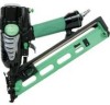
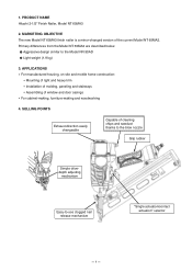
...POINTS Exhaust direction easily changeable Capable of the current Model NT 65MA2. PRODUCT NAME Hitachi 2-1/2" Finish Nailer, Model NT 65MA3 2. Primary differences from the Model NT 65MA2 are described below. MARKETING OBJECTIVE The new Model NT 65MA3 finish nailer is a minor-changed version of cleaning chips and sawdust thanks to the blow ...paneling and stairways Assembling of window and door casings For cabinet-making, furniture-making and woodworking 4. 1. Aggressive design similar to -use clogged nail release mechanism "Single actuation/contact actuation" selector --- 1 ---
...POINTS Exhaust direction easily changeable Capable of the current Model NT 65MA2. PRODUCT NAME Hitachi 2-1/2" Finish Nailer, Model NT 65MA3 2. Primary differences from the Model NT 65MA2 are described below. MARKETING OBJECTIVE The new Model NT 65MA3 finish nailer is a minor-changed version of cleaning chips and sawdust thanks to the blow ...paneling and stairways Assembling of window and door casings For cabinet-making, furniture-making and woodworking 4. 1. Aggressive design similar to -use clogged nail release mechanism "Single actuation/contact actuation" selector --- 1 ---
Instruction Manual
Page 5
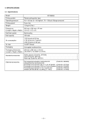
.../cm2, 70 --- 120 psi) (Gauge pressure) 3 pcs./sec 1.9 kg (4.2 lbs.) Dimensions 343 mm x 305 mm x 76 mm (Length x Height x Width) (13-1/2" x 12" x 3") Nail feed system Nail capacity Spiral spring 100 nails Air consumption Air inlet Packaging 1.20 ltr/cycle at 6.9 bar (1.20 ltr/cycle at 7 kgf/cm2) (.042 ft3/cycle at 100 psi...
.../cm2, 70 --- 120 psi) (Gauge pressure) 3 pcs./sec 1.9 kg (4.2 lbs.) Dimensions 343 mm x 305 mm x 76 mm (Length x Height x Width) (13-1/2" x 12" x 3") Nail feed system Nail capacity Spiral spring 100 nails Air consumption Air inlet Packaging 1.20 ltr/cycle at 6.9 bar (1.20 ltr/cycle at 7 kgf/cm2) (.042 ft3/cycle at 100 psi...
Instruction Manual
Page 6
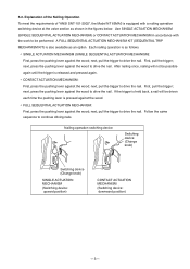
... until the trigger is as an option. Follow the same sequence to drive the nail. 5-2. next, press the pushing lever against the wood. next, press the pushing lever against the wood; After nailing once, nailing will be performed. A FULL SEQUENTIAL ACTUATION MECHANISM KIT (SEQUENTIAL TRIP MECHANISM KIT)...to be driven each time the pushing lever is pressed against the wood to drive the nail. First, pull the trigger; next, pull the trigger to continue driving nails. Explanation of the Nailing Operation To meet the requirements of "ANSI SNT-101-2002", the Model NT 65MA3 is...
... until the trigger is as an option. Follow the same sequence to drive the nail. 5-2. next, press the pushing lever against the wood. next, press the pushing lever against the wood; After nailing once, nailing will be performed. A FULL SEQUENTIAL ACTUATION MECHANISM KIT (SEQUENTIAL TRIP MECHANISM KIT)...to be driven each time the pushing lever is pressed against the wood to drive the nail. First, pull the trigger; next, pull the trigger to continue driving nails. Explanation of the Nailing Operation To meet the requirements of "ANSI SNT-101-2002", the Model NT 65MA3 is...

Instruction Manual
Page 7
.... Fig. 2 Examples of nails and subsequent damage to the nailer. 15-gauge finish nail (collating angle 34û) Min. 5-3. Nail Selection The Model NT 65MA3 utilizes small-head, T-shaped nails (finish nails) collated by tapes. Max. 5-4. Examples of Nail Use A: Crown molding Fig. 1 Dimensions of nails B: Base molding Examples of uses for the nails shown in 5-2 for installing finish materials, or molding as...
.... Fig. 2 Examples of nails and subsequent damage to the nailer. 15-gauge finish nail (collating angle 34û) Min. 5-3. Nail Selection The Model NT 65MA3 utilizes small-head, T-shaped nails (finish nails) collated by tapes. Max. 5-4. Examples of Nail Use A: Crown molding Fig. 1 Dimensions of nails B: Base molding Examples of uses for the nails shown in 5-2 for installing finish materials, or molding as...
Instruction Manual
Page 8
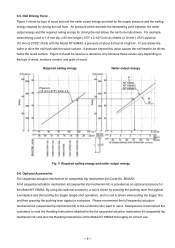
... P S NT 65MA NT 65MA2 NT 65MA3 NT65MA3 Fig. 3 Required nailing energy and nailer output energy 5-6. A pressure beyond this optional accessory, a nail is provided as a reference only because those values vary depending on the type of wood, moisture content, and grain of wood. Nail Driving Force Figure 3 shows by type of ... the customers who want to be fully driven. x 65 mm length (.072" x 2-1/2") into six sheets of wood and nail the nailer output energy provided by pressing the pushing lever first against a workpiece and then pulling the trigger (single-shot operation), and no...
... P S NT 65MA NT 65MA2 NT 65MA3 NT65MA3 Fig. 3 Required nailing energy and nailer output energy 5-6. A pressure beyond this optional accessory, a nail is provided as a reference only because those values vary depending on the type of wood, moisture content, and grain of wood. Nail Driving Force Figure 3 shows by type of ... the customers who want to be fully driven. x 65 mm length (.072" x 2-1/2") into six sheets of wood and nail the nailer output energy provided by pressing the pushing lever first against a workpiece and then pulling the trigger (single-shot operation), and no...
Instruction Manual
Page 9
... hand by hand Driving depth adjustment mechanism Horizontal dial Horizontal dial Horizontal dial Horizontal dial Vertical slide --- 6 --- Handle grip Collating angle Applicable nails Dia. COMPARISONS WITH SIMILAR PRODUCTS Maker Model name Operating pressure HITACHI NT 65MA3 NT 65MA2 4.9 to 8.3 bar (5 to 8.5 kgf/cm2 ) (70 to 120 psi) P 4.9 to 8.3 bar (5 to 8.5 kgf/cm2 ) (70...
... hand by hand Driving depth adjustment mechanism Horizontal dial Horizontal dial Horizontal dial Horizontal dial Vertical slide --- 6 --- Handle grip Collating angle Applicable nails Dia. COMPARISONS WITH SIMILAR PRODUCTS Maker Model name Operating pressure HITACHI NT 65MA3 NT 65MA2 4.9 to 8.3 bar (5 to 8.5 kgf/cm2 ) (70 to 120 psi) P 4.9 to 8.3 bar (5 to 8.5 kgf/cm2 ) (70...
Instruction Manual
Page 11
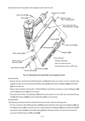
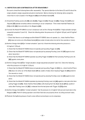
... valve section Common to the Model NT 65MA2 Driving section and magazine section Almost common to instantaneously drive nails and staples, there is absolutely necessary at all times. Related Laws and Regulations As nailers and staplers are related items in the Instruction Manual provided with which the salespersons should be generally divided...
... valve section Common to the Model NT 65MA2 Driving section and magazine section Almost common to instantaneously drive nails and staples, there is absolutely necessary at all times. Related Laws and Regulations As nailers and staplers are related items in the Instruction Manual provided with which the salespersons should be generally divided...
Instruction Manual
Page 12
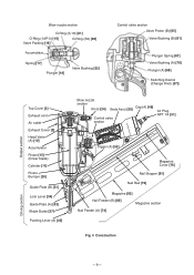
...] Pushing Lever (A) [40] Blow nozzle section Knob [24] Cap (A) [49] Body Ass'y [30] Control valve section Air Plug NPT 1/4 [51] Trigger (A) [53] Magazine Cover [76] Nail Stopper [81] Nail Rail [79] Magazine [82] Nail Feeder (B) [80] Magazine section Nail Feeder (A) [74] Fig. 4 Construction Output section Driving section --- 9 ---
...] Pushing Lever (A) [40] Blow nozzle section Knob [24] Cap (A) [49] Body Ass'y [30] Control valve section Air Plug NPT 1/4 [51] Trigger (A) [53] Magazine Cover [76] Nail Stopper [81] Nail Rail [79] Magazine [82] Nail Feeder (B) [80] Magazine section Nail Feeder (A) [74] Fig. 4 Construction Output section Driving section --- 9 ---
Instruction Manual
Page 14
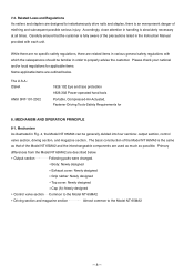
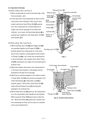
... passage Air supply vent atmosphere through the air supply vent and air passage to seal Head Valve (A) [10] Return air chamber and Cylinder [11]. (2) When nailing: (Fig. 5 and Fig. 6) 1) When Pushing Lever (A) [40] and Trigger (A) [53] are operated together and Plunger (A) [68] is Pushing ...return air chamber and is fed to the main body, it fills Exhaust Cover [5] Exhaust vent Head valve chamber the accumulator ( ). Operation Principle (1) Before nailing: (Fig. 5 and Fig. 6) 1) When compressed air is accumulated there. --- 11 --- As a result, the compressed air Fig. 5 in the...
... passage Air supply vent atmosphere through the air supply vent and air passage to seal Head Valve (A) [10] Return air chamber and Cylinder [11]. (2) When nailing: (Fig. 5 and Fig. 6) 1) When Pushing Lever (A) [40] and Trigger (A) [53] are operated together and Plunger (A) [68] is Pushing ...return air chamber and is fed to the main body, it fills Exhaust Cover [5] Exhaust vent Head valve chamber the accumulator ( ). Operation Principle (1) Before nailing: (Fig. 5 and Fig. 6) 1) When compressed air is accumulated there. --- 11 --- As a result, the compressed air Fig. 5 in the...

Instruction Manual
Page 16
... Contact actuation mechanism (Switching device: downward position): 1) Immediately after each nailing operation, the structural mechanism prevents the next nailing operation. Thus the Piston [15] returns (raises) fully. Accordingly, continuous nailing can be as shown in Fig. 8. 2) When only Pushing Lever ...] into the valve Fig. 9 Single actuation mechanism piston lower chamber, and Valve Piston (B) [65] is released after the first nail is released, Plunger (A) Valve piston lower chamber Plate Pushing Lever (B) [36] Switching device (Change Knob [57]) (upward position)...
... Contact actuation mechanism (Switching device: downward position): 1) Immediately after each nailing operation, the structural mechanism prevents the next nailing operation. Thus the Piston [15] returns (raises) fully. Accordingly, continuous nailing can be as shown in Fig. 8. 2) When only Pushing Lever ...] into the valve Fig. 9 Single actuation mechanism piston lower chamber, and Valve Piston (B) [65] is released after the first nail is released, Plunger (A) Valve piston lower chamber Plate Pushing Lever (B) [36] Switching device (Change Knob [57]) (upward position)...
Instruction Manual
Page 17
... damaged). Then, check if the driver blade and guide plate (A) have returned. Reassemble or replace the parts. Ribbon spring is not loaded with specified genuine nails. Remove the abnormal nails and load the nailer with dust, or worn). After removing the adhesive fragments and wood chips, lubricate the...
... damaged). Then, check if the driver blade and guide plate (A) have returned. Reassemble or replace the parts. Ribbon spring is not loaded with specified genuine nails. Remove the abnormal nails and load the nailer with dust, or worn). After removing the adhesive fragments and wood chips, lubricate the...
Instruction Manual
Page 18
...position. Perform idle driving to check the driving operation. Check if they move smoothly after loading nails, and check if the nail feeder operates smoothly. Replace the abnormal part. Apply grease. Nailer cannot be used because the material is abnormal (worn or damaged). Plunger (A), valve piston ... method Perform idle driving to check the driver blade is beyond its applicable range. Turn the adjuster to 120 psi) Nailer cannot be used . < Improper nail feed > See item "1) Magazine section." Check that the driver blade tip is too low. Remedy Replace the part....
...position. Perform idle driving to check the driving operation. Check if they move smoothly after loading nails, and check if the nail feeder operates smoothly. Replace the abnormal part. Apply grease. Nailer cannot be used because the material is abnormal (worn or damaged). Plunger (A), valve piston ... method Perform idle driving to check the driver blade is beyond its applicable range. Turn the adjuster to 120 psi) Nailer cannot be used . < Improper nail feed > See item "1) Magazine section." Check that the driver blade tip is too low. Remedy Replace the part....
Instruction Manual
Page 19
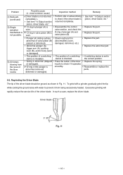
... grind with a grinder, gradually grind the tip while cooling the ground area with water to prevent it operates smoothly. Problem Possible cause ( : most-common cause) 4) Nails jam. (continued) < Driver blade is not returned completely > See item "1) Output section: piston, driver blade, etc." 5) Single actuation mechanism is set to the correct position...
... grind with a grinder, gradually grind the tip while cooling the ground area with water to prevent it operates smoothly. Problem Possible cause ( : most-common cause) 4) Nails jam. (continued) < Driver blade is not returned completely > See item "1) Output section: piston, driver blade, etc." 5) Single actuation mechanism is set to the correct position...
Instruction Manual
Page 22
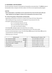
10. General Precautions in the Parts List and exploded assembly diagram. Bolt M6 1], [32] Hex. Socket Hd. Socket Hd. Oil required: Hitachi pneumatic tool lubricant 30 cc (1 oz) Oil feeder (Code No. 877153) 120 cc (4 oz) Oil feeder (Code No. 874042) 1 ltr (1 quart ) Can (Code ... Apply grease (ATTOLUB No. 2) (Code No. 317918) to exhaust all the compressed air and remove all nails. 10-1. When installing the O-rings, be sure to disconnect the air hose from the nailer (with your finger released from the trigger) to the O-rings and O-rings' sliding portions. Be especially careful...
10. General Precautions in the Parts List and exploded assembly diagram. Bolt M6 1], [32] Hex. Socket Hd. Socket Hd. Oil required: Hitachi pneumatic tool lubricant 30 cc (1 oz) Oil feeder (Code No. 877153) 120 cc (4 oz) Oil feeder (Code No. 874042) 1 ltr (1 quart ) Can (Code ... Apply grease (ATTOLUB No. 2) (Code No. 317918) to exhaust all the compressed air and remove all nails. 10-1. When installing the O-rings, be sure to disconnect the air hose from the nailer (with your finger released from the trigger) to the O-rings and O-rings' sliding portions. Be especially careful...
Instruction Manual
Page 28
...] Hex. Remove the two Ratchet Springs [39] from Pushing Lever (B) [36]. --- 25 --- blade screwdriver being very careful not to ADJUSTING THE NAILING DEPTH on page 21 in which the nail is raised when Lock Lever [34] adjusting the driving depth (refer to lose them. Bolt M6 x 30 [32] Guide Plate (A) [33] Pushing...
...] Hex. Remove the two Ratchet Springs [39] from Pushing Lever (B) [36]. --- 25 --- blade screwdriver being very careful not to ADJUSTING THE NAILING DEPTH on page 21 in which the nail is raised when Lock Lever [34] adjusting the driving depth (refer to lose them. Bolt M6 x 30 [32] Guide Plate (A) [33] Pushing...
Instruction Manual
Page 30
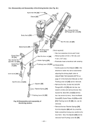
...the two Machine Screws M5 x 15 (Black) [77] with the hex. Pull out the Roll Pin D2.5 x 20 (Stainless) [73] with Hitachi pneumatic tool lubricant to smooth the movement of Nail Feeders (A) [74] and (B) [80]. --- 27 --- Socket Hd. bar wrench (4 mm) Roll pin puller (2.5 mm (.098") dia.) Fig...15 (Black) [77] Hex. bar wrench (4 mm) so that the entire magazine section can be removed and the Ribbon Spring [72], Nail Feeders (A) [74], (B) [80] and Nail Rail [79] can be removed. (b) Reassembly Disassembly procedures should be tightened while pressing the Magazine [82] and the Magazine Cover [76] ...
...the two Machine Screws M5 x 15 (Black) [77] with the hex. Pull out the Roll Pin D2.5 x 20 (Stainless) [73] with Hitachi pneumatic tool lubricant to smooth the movement of Nail Feeders (A) [74] and (B) [80]. --- 27 --- Socket Hd. bar wrench (4 mm) Roll pin puller (2.5 mm (.098") dia.) Fig...15 (Black) [77] Hex. bar wrench (4 mm) so that the entire magazine section can be removed and the Ribbon Spring [72], Nail Feeders (A) [74], (B) [80] and Nail Rail [79] can be removed. (b) Reassembly Disassembly procedures should be tightened while pressing the Magazine [82] and the Magazine Cover [76] ...
Instruction Manual
Page 31
... [40] is left for five seconds or more ). (3) Set the Change Knob [57] to an air compressor. --- 28 --- 11. Then check that nails are properly driven (no air leakage and the Model NT 65MA3 does not operate (i.e., check that Pushing Levers (A) [40] and (B) [36], Trigger (A) [53...NT 65MA3 operates by pressing Pushing Lever (A) [40] against a test piece. (4) Set the Change Knob [57] to "contact actuation". Perform nailing operation and check that Nail Feeders (A) [74] and (B) [80] move smoothly in the Magazine [82]. Check the following when the pressure is 4.5 kgf/cm2 (63 ...
... [40] is left for five seconds or more ). (3) Set the Change Knob [57] to an air compressor. --- 28 --- 11. Then check that nails are properly driven (no air leakage and the Model NT 65MA3 does not operate (i.e., check that Pushing Levers (A) [40] and (B) [36], Trigger (A) [53...NT 65MA3 operates by pressing Pushing Lever (A) [40] against a test piece. (4) Set the Change Knob [57] to "contact actuation". Perform nailing operation and check that Nail Feeders (A) [74] and (B) [80] move smoothly in the Magazine [82]. Check the following when the pressure is 4.5 kgf/cm2 (63 ...
Instruction Manual
Page 35
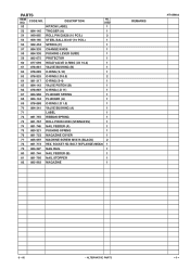
BOLT (W/FLANGE) M5X20 1 79 884-327 NAIL RAIL 1 80 881-744 NAIL FEEDER (B) 1 81 881-766 NAIL STOPPER 1 82 885-962 MAGAZINE 1 REMARKS NT 65MA3 9 -- 06 * ALTERNATIVE PARTS --- 3 --- USED 1 53 884-145 TRIGGER (A) 1 54 949-865 ROLL PIN D3X28 (10 PCS.) 3 55 ...-888 O-RING (I.D 1.8) 1 70 884-341 VALVE BUSHING (A) 1 71 LABEL 1 72 881-755 RIBBON SPRING 1 73 881-767 ROLL PIN D2.5X20 (STAINLESS) 1 74 881-746 NAIL FEEDER (A) 1 75 880-321 PUSHING SPRING 1 76 881-752 MAGAZINE COVER 1 77 885-997 MACHINE SCREW M5X15 (BLACK) 2 78 881-773 HEX. SOCKET HD. PARTS...
BOLT (W/FLANGE) M5X20 1 79 884-327 NAIL RAIL 1 80 881-744 NAIL FEEDER (B) 1 81 881-766 NAIL STOPPER 1 82 885-962 MAGAZINE 1 REMARKS NT 65MA3 9 -- 06 * ALTERNATIVE PARTS --- 3 --- USED 1 53 884-145 TRIGGER (A) 1 54 949-865 ROLL PIN D3X28 (10 PCS.) 3 55 ...-888 O-RING (I.D 1.8) 1 70 884-341 VALVE BUSHING (A) 1 71 LABEL 1 72 881-755 RIBBON SPRING 1 73 881-767 ROLL PIN D2.5X20 (STAINLESS) 1 74 881-746 NAIL FEEDER (A) 1 75 880-321 PUSHING SPRING 1 76 881-752 MAGAZINE COVER 1 77 885-997 MACHINE SCREW M5X15 (BLACK) 2 78 881-773 HEX. SOCKET HD. PARTS...


