Instruction Manual
Page 13
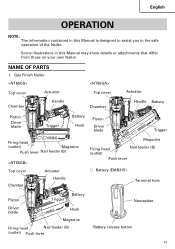
Some illustrations in the safe operation of the Nailer. Gas Finish Nailer Top cover Actuator Chamber Handle Top cover Chamber Actuator Handle Battery Piston Driver blade Trigger Battery Hook Piston Driver blade Trigger Firing head (outlet) Magazine ... information contained in this Manual is designed to assist you in this Manual may show details or attachments that differ from those on your own Nailer.
Some illustrations in the safe operation of the Nailer. Gas Finish Nailer Top cover Actuator Chamber Handle Top cover Chamber Actuator Handle Battery Piston Driver blade Trigger Battery Hook Piston Driver blade Trigger Firing head (outlet) Magazine ... information contained in this Manual is designed to assist you in this Manual may show details or attachments that differ from those on your own Nailer.
Instruction Manual
Page 15
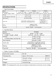
Gas Finish Nailer Model Dimensions Length × Height × Width Weight Includes battery and fuel cell Nail capacity Cycle rate Battery Fuel Cell NT65GS NT65GB NT65GA 10-1/4" × 11" × 3-3/8" 10-5/8" × 11-1/8" × 3-3/8" 12" × 12" × 5" (260 mm × 278 mm ... Continuous: 900 nails per hour EBM315 (1.5 Ah) Li-ion battery, 3.6 V Type No. 728-981......sold separately 2. Battery Charger (UC3SML) Input power source Charging time Charger Weight DC 12V Approx. 60 minutes EBM315 Charging voltage DC 3.6 V Charging current DC 1.5 A 0.4 lbs (0.2 kg) NOTE...
Gas Finish Nailer Model Dimensions Length × Height × Width Weight Includes battery and fuel cell Nail capacity Cycle rate Battery Fuel Cell NT65GS NT65GB NT65GA 10-1/4" × 11" × 3-3/8" 10-5/8" × 11-1/8" × 3-3/8" 12" × 12" × 5" (260 mm × 278 mm ... Continuous: 900 nails per hour EBM315 (1.5 Ah) Li-ion battery, 3.6 V Type No. 728-981......sold separately 2. Battery Charger (UC3SML) Input power source Charging time Charger Weight DC 12V Approx. 60 minutes EBM315 Charging voltage DC 3.6 V Charging current DC 1.5 A 0.4 lbs (0.2 kg) NOTE...
Instruction Manual
Page 16
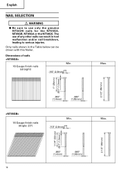
... only the genuine HITACHI nails for the NT65GS, NT65GB, NT65GA or the NT50GS. English NAIL SELECTION WARNING ⅷ Be sure to serious injuries. Only nails shown in tool malfunction and/or nail breakdown, leading to use of nails 16 Gauge finish nails (straight) Min. .110" (2.8mm) Max. 2-1/2" (65mm) 1" (25mm) .051" (1.3mm) .055" (1.4mm) .065" (1.65mm) 16 Gauge finish nails (Angle...
... only the genuine HITACHI nails for the NT65GS, NT65GB, NT65GA or the NT50GS. English NAIL SELECTION WARNING ⅷ Be sure to serious injuries. Only nails shown in tool malfunction and/or nail breakdown, leading to use of nails 16 Gauge finish nails (straight) Min. .110" (2.8mm) Max. 2-1/2" (65mm) 1" (25mm) .051" (1.3mm) .055" (1.4mm) .065" (1.65mm) 16 Gauge finish nails (Angle...
Instruction Manual
Page 24
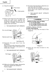
... NOT OPERATE. Magazine (2) Slide the nail strip forward in that is observed, you may load nails in the actual application. Ⅺ THE NAILER MUST OPERATE PROPERLY. (4) Remove the finger from the workpiece. Depress push lever Nail feeder (B) (5) Separate the push lever from the trigger and... the trigger, depress the push lever against the workpiece with pulling back the nail feeder (B). (NT50GS: Unnecessary to be used in the Nailer. English 4 Close the actuator. 2. Do not pull trigger LOADING NAILS WARNING ⅷ When loading nails into the back of the magazine.
... NOT OPERATE. Magazine (2) Slide the nail strip forward in that is observed, you may load nails in the actual application. Ⅺ THE NAILER MUST OPERATE PROPERLY. (4) Remove the finger from the workpiece. Depress push lever Nail feeder (B) (5) Separate the push lever from the trigger and... the trigger, depress the push lever against the workpiece with pulling back the nail feeder (B). (NT50GS: Unnecessary to be used in the Nailer. English 4 Close the actuator. 2. Do not pull trigger LOADING NAILS WARNING ⅷ When loading nails into the back of the magazine.

Instruction Manual
Page 27
...be pushed up . To ensure that gets on the opposite side. ⅷ Never use Nailer which is defective or operating abnormally. ⅷ Do not use Nailer as required. 3 2 Push lever Trigger 27 NT65GS, NT65GA, NT65GB employ a preventive mechanism for an extended period may lead to oil around the exhaust...a nail. CAUTION ⅷ Use caution not to throw the push lever tip onto wood when the push lever cannot be pushed up . This Nailer is depressed (upward position). This takes place when the magazine is completely depressed. 3 Pull and squeeze the trigger to drive a nail. 4 ...
...be pushed up . To ensure that gets on the opposite side. ⅷ Never use Nailer which is defective or operating abnormally. ⅷ Do not use Nailer as required. 3 2 Push lever Trigger 27 NT65GS, NT65GA, NT65GB employ a preventive mechanism for an extended period may lead to oil around the exhaust...a nail. CAUTION ⅷ Use caution not to throw the push lever tip onto wood when the push lever cannot be pushed up . This Nailer is depressed (upward position). This takes place when the magazine is completely depressed. 3 Pull and squeeze the trigger to drive a nail. 4 ...
Instruction Manual
Page 29
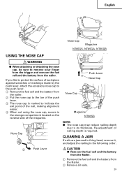
... or markings made by the push lever, attach the accessory nose cap to the push lever. 1 Remove the fuel cell and the battery from the nailer. 2 Put the nose cap to the toe of the push lever. 3 The nose cap is required. CLEARING A JAM If nails are jammed in firing head... cap may reduce nailing depth due to remove your finger from the trigger and remove the fuel cell and the battery from the Nailer. 2 Remove all nails. 29 English Nose Cap Magazine NT65GS, NT65GA, NT65GB USING THE NOSE CAP WARNING ⅷ When attaching or detaching the nose cap, be sure to its thickness.
... or markings made by the push lever, attach the accessory nose cap to the push lever. 1 Remove the fuel cell and the battery from the nailer. 2 Put the nose cap to the toe of the push lever. 3 The nose cap is required. CLEARING A JAM If nails are jammed in firing head... cap may reduce nailing depth due to remove your finger from the trigger and remove the fuel cell and the battery from the Nailer. 2 Remove all nails. 29 English Nose Cap Magazine NT65GS, NT65GA, NT65GB USING THE NOSE CAP WARNING ⅷ When attaching or detaching the nose cap, be sure to its thickness.
Instruction Manual
Page 107
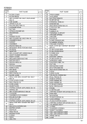
... 1 1 1 1 1 4 1 2 2 2 1 1 4 1 1 1 4 1 1 1 2 1 1 2 1 2 1 1 1 1 1 2 1 3 1 1 1 1 2 1 1 1 1 3 1 2 4 4 1 1 1 1 1 1 1 ITEM NO. SCREW M4 89 ROLL PIN D3×16 90 RIBBON SPRING 91 NAIL FEEDER (B) 92 NAIL FEEDER (A) 93 PUSHING SPRING 94 ROLL PIN D2.5×26 95 PRISM 96 CONTROLLER 97 TAPPING SCREW...HITACHI PLATE 46 TAPPING SCREW (W/FLANGE) D4×20 47 SEAL LOCK HEX. BAR WRENCH 3MM 504 HEX. PART NAME 1 FILTER COVER 2 FILTER MESH 3 HEX. BOLT M4×16 14 CHAMBER HEAD 15 GASKET 16 CHAMBER 17 PISTON RING (B) 18 RETAINING RING FOR D40 HOLE 19 PACKING 20 ADAPTER 21 HEX. NT65GA...
... 1 1 1 1 1 4 1 2 2 2 1 1 4 1 1 1 4 1 1 1 2 1 1 2 1 2 1 1 1 1 1 2 1 3 1 1 1 1 2 1 1 1 1 3 1 2 4 4 1 1 1 1 1 1 1 ITEM NO. SCREW M4 89 ROLL PIN D3×16 90 RIBBON SPRING 91 NAIL FEEDER (B) 92 NAIL FEEDER (A) 93 PUSHING SPRING 94 ROLL PIN D2.5×26 95 PRISM 96 CONTROLLER 97 TAPPING SCREW...HITACHI PLATE 46 TAPPING SCREW (W/FLANGE) D4×20 47 SEAL LOCK HEX. BAR WRENCH 3MM 504 HEX. PART NAME 1 FILTER COVER 2 FILTER MESH 3 HEX. BOLT M4×16 14 CHAMBER HEAD 15 GASKET 16 CHAMBER 17 PISTON RING (B) 18 RETAINING RING FOR D40 HOLE 19 PACKING 20 ADAPTER 21 HEX. NT65GA...

