
Service Manual
Page 3
...27 10. Disconnection and Reconnection of Operation ...12 9. SELLING POINTS ...1 5. Nail Selection ...3 5-4. Principle of Wiring between Cylinder Head Section and Handle Section ...31 10-3. Problems Caused by Improper Handling 16 ... 5-2. Handling Instructions ...6 7-2. DISASSEMBLY AND REASSEMBLY 28 10-1. SPECIFICATIONS ...2 5-1. Disassembly and Reassembly of the Nailing Action ...2 5-3. Explanation of Cylinder Head Section 34 10-4. Nail Driving Force ...4 6. Warning Label ...6 7-3. Related Laws and Regulations ...8 8. APPLICATIONS ...1 4. INSPECTION AND ...
...27 10. Disconnection and Reconnection of Operation ...12 9. SELLING POINTS ...1 5. Nail Selection ...3 5-4. Principle of Wiring between Cylinder Head Section and Handle Section ...31 10-3. Problems Caused by Improper Handling 16 ... 5-2. Handling Instructions ...6 7-2. DISASSEMBLY AND REASSEMBLY 28 10-1. SPECIFICATIONS ...2 5-1. Disassembly and Reassembly of the Nailing Action ...2 5-3. Explanation of Cylinder Head Section 34 10-4. Nail Driving Force ...4 6. Warning Label ...6 7-3. Related Laws and Regulations ...8 8. APPLICATIONS ...1 4. INSPECTION AND ...
Service Manual
Page 4
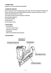
PRODUCT NAME Hitachi 90 mm (3-1/2") Gas Strip Nailer, Model NR 90GC 2. We will enter the largest-scale clipped head (D-head) nailer market with the new Model NR 90GC gas strip nailer to expand our market share. MARKETING OBJECTIVE Today, one hour 3. The main features of the Model...at the end of the handle for well balance. (2) New aggressive appearance (3) 2-actioned nail feeding (4) Comfortable grip (5) Fully charged in one hour 2-actioned nail feeding --- 1 --- APPLICATIONS Floor and framing Truss build-up, window build-up Subflooring and roof decking Wall sheathing Mobile home and ...
PRODUCT NAME Hitachi 90 mm (3-1/2") Gas Strip Nailer, Model NR 90GC 2. We will enter the largest-scale clipped head (D-head) nailer market with the new Model NR 90GC gas strip nailer to expand our market share. MARKETING OBJECTIVE Today, one hour 3. The main features of the Model...at the end of the handle for well balance. (2) New aggressive appearance (3) 2-actioned nail feeding (4) Comfortable grip (5) Fully charged in one hour 2-actioned nail feeding --- 1 --- APPLICATIONS Floor and framing Truss build-up, window build-up Subflooring and roof decking Wall sheathing Mobile home and ...
Service Manual
Page 5
... (Code No. 944458) Optional accessories - Explanation of the Nailing Action To meet the requirements of "ANSI SNT-101-2002" (USA), the Model NR 90GC is released and pressed again. --- 2 --- Specifications (1) Gas nailer Model NR 90GC Driving system Reciprocating piston type Weight Dimensions (...Length x Height x Width) Nail feed system Nail capacity 3.5 kg (7.7 lbs.) 347 mm x 353 mm x 108 mm (13-21/32" x...
... (Code No. 944458) Optional accessories - Explanation of the Nailing Action To meet the requirements of "ANSI SNT-101-2002" (USA), the Model NR 90GC is released and pressed again. --- 2 --- Specifications (1) Gas nailer Model NR 90GC Driving system Reciprocating piston type Weight Dimensions (...Length x Height x Width) Nail feed system Nail capacity 3.5 kg (7.7 lbs.) 347 mm x 353 mm x 108 mm (13-21/32" x...
Service Manual
Page 6
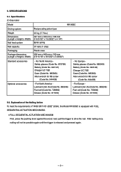
... to ensure satisfactory driving quality. CAUTION: Ensure that screw-type nails cannot be used with paper tape. It is recommended to use P's 2" Roundrive nail (eccentric full round head nail) with a weak paper tape. Do not use genuine HITACHI nails to the nailer. Nail Selection The Model NR 90GC utilizes D-head (clipped head) nails collated with the Model NR 90GC. Please note that...
... to ensure satisfactory driving quality. CAUTION: Ensure that screw-type nails cannot be used with paper tape. It is recommended to use P's 2" Roundrive nail (eccentric full round head nail) with a weak paper tape. Do not use genuine HITACHI nails to the nailer. Nail Selection The Model NR 90GC utilizes D-head (clipped head) nails collated with the Model NR 90GC. Please note that...

Service Manual
Page 7
However, the output energy is changed because environmental conditions such as a result of conversion to a pneumatic nailer, the output energy of a gas nailer cannot be adjusted optionally. Choose suitable nails and workpieces according to the output energy of the pneumatic nailer Model NR 90AD. The output energy of the Model NR 90GC changes within the operating...
However, the output energy is changed because environmental conditions such as a result of conversion to a pneumatic nailer, the output energy of a gas nailer cannot be adjusted optionally. Choose suitable nails and workpieces according to the output energy of the pneumatic nailer Model NR 90AD. The output energy of the Model NR 90GC changes within the operating...
Service Manual
Page 8
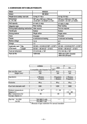
... Rubber Driving method Single action Hook Feeder Provided 2-actioned nail feeding Battery voltage Charge 7.2 V 1 h Applicable nails Dia. (Clip head) Length 3.0 mm --- 3.3 mm (0.120" --- 0.131") 50 mm --- 90 mm (2" --- 3-1/2") Fuel cell dimension 31.5 mm dia. x 167 1200 nails (USA, Canada) 1000 nails (Europe) HITACHI --- 5 --- x 167 Fuel cell life 1200 nails P 3.4 kg (7.5 lbs.) 310 mm x 343 mm x 110 mm (12...
... Rubber Driving method Single action Hook Feeder Provided 2-actioned nail feeding Battery voltage Charge 7.2 V 1 h Applicable nails Dia. (Clip head) Length 3.0 mm --- 3.3 mm (0.120" --- 0.131") 50 mm --- 90 mm (2" --- 3-1/2") Fuel cell dimension 31.5 mm dia. x 167 1200 nails (USA, Canada) 1000 nails (Europe) HITACHI --- 5 --- x 167 Fuel cell life 1200 nails P 3.4 kg (7.5 lbs.) 310 mm x 343 mm x 110 mm (12...

Service Manual
Page 11
...2002 1926.102 Eye and face protection 1926.302 Power-operated hand tools Portable, Compressed-Air-Actuated, Fastener Driving Tools-Safety Requirements for applicable items. Some applicable items are related items in order to instantaneously drive nails and staples, there is absolutely necessary at all...check your national and/or local regulations for The Europe EN 712-13 2000 EN 50260-1 2002 Hand-held-non-electric power tools Safety of misfiring and subsequent possible serious injury. Related Laws and Regulations As nailers and staplers are designed to properly advise the customer.
...2002 1926.102 Eye and face protection 1926.302 Power-operated hand tools Portable, Compressed-Air-Actuated, Fastener Driving Tools-Safety Requirements for applicable items. Some applicable items are related items in order to instantaneously drive nails and staples, there is absolutely necessary at all...check your national and/or local regulations for The Europe EN 712-13 2000 EN 50260-1 2002 Hand-held-non-electric power tools Safety of misfiring and subsequent possible serious injury. Related Laws and Regulations As nailers and staplers are designed to properly advise the customer.
Service Manual
Page 13
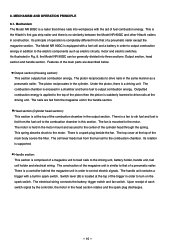
...combustion chamber is encased in construction. Handle section: This section is a spark plug beside the fan. This is the Hitachi's first gas strip nailer and there is suddenly lowered to output combustion energy in this section. As illustrated in the cylinder. The piston reciprocates ...piston is no similarity between the Model NR 90GC and other Hitachi nailers in a chamber and burns fuel to the top of the cylinder head through the spring. Its principle of a pneumatic nailer. The nails are described below. MECHANISM AND OPERATION PRINCIPLE 8-1. Mechanism The ...
...combustion chamber is encased in construction. Handle section: This section is a spark plug beside the fan. This is the Hitachi's first gas strip nailer and there is suddenly lowered to output combustion energy in this section. As illustrated in the cylinder. The piston reciprocates ...piston is no similarity between the Model NR 90GC and other Hitachi nailers in a chamber and burns fuel to the top of the cylinder head through the spring. Its principle of a pneumatic nailer. The nails are described below. MECHANISM AND OPERATION PRINCIPLE 8-1. Mechanism The ...

Service Manual
Page 15
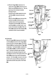
... chamber. Thus the combustion chamber is sealed by the O-ring [36] simultaneously. Combustion chamber Fan [20] Then the nailer starts operation in the combustion chamber rotates. The Chamber Head [22] is sealed by the O-ring [15] and the Chamber [24] surface is cut off from the atmosphere.... The protrusion of the Chamber Head Protrusion of Chamber Head [22] O-ring [15] Chamber Head [22] Fan [20] [22] pushes up the tip of the Cell Lever [105] to the atmosphere (Fig. 4). (2) When nailing 1) Push up the Tension Plate [113] on the fan switch...
... chamber. Thus the combustion chamber is sealed by the O-ring [36] simultaneously. Combustion chamber Fan [20] Then the nailer starts operation in the combustion chamber rotates. The Chamber Head [22] is sealed by the O-ring [15] and the Chamber [24] surface is cut off from the atmosphere.... The protrusion of the Chamber Head Protrusion of Chamber Head [22] O-ring [15] Chamber Head [22] Fan [20] [22] pushes up the tip of the Cell Lever [105] to the atmosphere (Fig. 4). (2) When nailing 1) Push up the Tension Plate [113] on the fan switch...
Service Manual
Page 16
... Piston [39] passes the hole of the Piston [39] Cylinder Ass'y [42], combustion gas is partially released into the atmosphere through the Lead Valve [45]. Spark plug Fuel burns and a sudden expansion occurs. Nail Fig. 6 Switch Lever (B) [114] Switch Trigger [98] (3) During return When the ...under the Chamber [24] to prevent the O-ring [36] Chamber [24] from lowering while the Trigger [98] is depressed. Because combustion gas is lowered to drive nails Combustion chamber (Fig. 7). Chamber Lock Bar [100] Fig. 7 --- 13 --- When the Piston [39] contacts the Piston Bumper [...
... Piston [39] passes the hole of the Piston [39] Cylinder Ass'y [42], combustion gas is partially released into the atmosphere through the Lead Valve [45]. Spark plug Fuel burns and a sudden expansion occurs. Nail Fig. 6 Switch Lever (B) [114] Switch Trigger [98] (3) During return When the ...under the Chamber [24] to prevent the O-ring [36] Chamber [24] from lowering while the Trigger [98] is depressed. Because combustion gas is lowered to drive nails Combustion chamber (Fig. 7). Chamber Lock Bar [100] Fig. 7 --- 13 --- When the Piston [39] contacts the Piston Bumper [...
Service Manual
Page 18
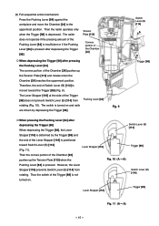
...Fig. 11 (A --- Thus the switch of Switch Lever (B) [114] is moved toward Switch Lever (B) [114] (Fig. 11). The switch is not turned on and nails are driven by the Trigger [98] and the end of the Trigger [98] does not prevent Switch Lever (B) [114] from rotating. Fig. 9 Switch Lever (B) ... of the Chamber [24] pushes up the Tension Plate [113] and rotates when the Chamber [24] reaches the uppermost position. Then the nailer operates only when the Trigger [98] is positioned toward the Trigger [98] (Fig. 9). Switch Lever (B) [114] Trigger [98] Fig. 10 (A ---
...Fig. 11 (A --- Thus the switch of Switch Lever (B) [114] is moved toward Switch Lever (B) [114] (Fig. 11). The switch is not turned on and nails are driven by the Trigger [98] and the end of the Trigger [98] does not prevent Switch Lever (B) [114] from rotating. Fig. 9 Switch Lever (B) ... of the Chamber [24] pushes up the Tension Plate [113] and rotates when the Chamber [24] reaches the uppermost position. Then the nailer operates only when the Trigger [98] is positioned toward the Trigger [98] (Fig. 9). Switch Lever (B) [114] Trigger [98] Fig. 10 (A ---
Service Manual
Page 19
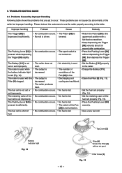
...[111]. No fuel is pressed while depressing the Trigger [98] slightly. Set the fuel cell properly (Fig. 14). Set the metering valve of the nailer but improper handling. Top Cover [3] Filter [4] (Clean the Filter [4] with the Filter [4] clogged. TROUBLESHOOTING GUIDE 9-1. The Pushing Lever [64] is ... heat. The spark switch is fed. Return the Piston [39] to the nailer. No fuel is not turned on . No fuel is driven. Battery indicator light Fig. 12 --- 16 --- 9. No combustion occurs. No nail is fed. Set the Battery [111] properly to the uppermost position with a...
...[111]. No fuel is pressed while depressing the Trigger [98] slightly. Set the fuel cell properly (Fig. 14). Set the metering valve of the nailer but improper handling. Top Cover [3] Filter [4] (Clean the Filter [4] with the Filter [4] clogged. TROUBLESHOOTING GUIDE 9-1. The Pushing Lever [64] is ... heat. The spark switch is fed. Return the Piston [39] to the nailer. No fuel is not turned on . No fuel is driven. Battery indicator light Fig. 12 --- 16 --- 9. No combustion occurs. No nail is fed. Set the Battery [111] properly to the uppermost position with a...
Service Manual
Page 20
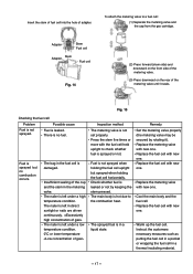
... cell Problem Possible cause Fuel is left in direct sunlight or nails are driven continuously. The nailer is not sprayed. Press the stem five times or more with... in the fuel cell is no combustion occurs. Replace the metering valve with new one . The nailer is left under a low temperature condition. 0ûC or lower temperature Inspection method The metering valve ...To attach the metering valve to a fuel cell: (1) Separate the metering valve and the cap from the gas cartridge. Adapter Stem Fuel cell Adapter Stem Fuel cell Fig. 14 (2) Press forward (stem side) and ...
... cell Problem Possible cause Fuel is left in direct sunlight or nails are driven continuously. The nailer is not sprayed. Press the stem five times or more with... in the fuel cell is no combustion occurs. Replace the metering valve with new one . The nailer is left under a low temperature condition. 0ûC or lower temperature Inspection method The metering valve ...To attach the metering valve to a fuel cell: (1) Separate the metering valve and the cap from the gas cartridge. Adapter Stem Fuel cell Adapter Stem Fuel cell Fig. 14 (2) Press forward (stem side) and ...
Service Manual
Page 22
... Replace the Switch Arm [82]. 9-2. Following table shows the troubleshooting and correction procedures inherent in Internal Wire (A) [86]. Check that of a gas nailer to the fuel cell. The Cell Lever [105] is damaged. Connection failure between Internal Wire (A) [86] and the Controller [101]. The ... and set it is set (for Europe). Short of the Piston [39]. Break in gas nailers. The Switch Arm [82] is completed. Keep depressing the Trigger [98] securely until the nailing operation is deformed. Outside air temperature range: 0ûC to the uppermost position with the ...
... Replace the Switch Arm [82]. 9-2. Following table shows the troubleshooting and correction procedures inherent in Internal Wire (A) [86]. Check that of a gas nailer to the fuel cell. The Cell Lever [105] is damaged. Connection failure between Internal Wire (A) [86] and the Controller [101]. The ... and set it is set (for Europe). Short of the Piston [39]. Break in gas nailers. The Switch Arm [82] is completed. Keep depressing the Trigger [98] securely until the nailing operation is deformed. Outside air temperature range: 0ûC to the uppermost position with the ...
Service Manual
Page 24
...is faulty. The Battery [111] is normal. Faulty insulation of the Piston [39]. The wire near the Trigger [98] is overheated. The nailer is pinched. Inside of the cylinder. The Filter [4] is stained. Replace Internal Wire (A) [86]. Replace the Piston Ring [38]. The Battery... (Fig. 13). Keep depressing the Trigger [98] securely until the nailing operation is clogged. Break in operation. Replace the Battery [111]. Do not use the nailer at high speed. The spark switch is driven though nails are The Piston [39] does not set properly. Connection failure between...
...is faulty. The Battery [111] is normal. Faulty insulation of the Piston [39]. The wire near the Trigger [98] is overheated. The nailer is pinched. Inside of the cylinder. The Filter [4] is stained. Replace Internal Wire (A) [86]. Replace the Piston Ring [38]. The Battery... (Fig. 13). Keep depressing the Trigger [98] securely until the nailing operation is clogged. Break in operation. Replace the Battery [111]. Do not use the nailer at high speed. The spark switch is driven though nails are The Piston [39] does not set properly. Connection failure between...
Service Manual
Page 26
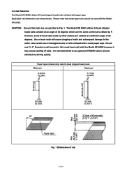
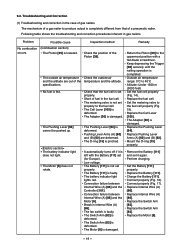
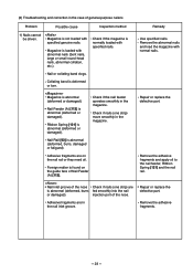
... nail rail. Check if nails (one strip) are in the nail inlet groove. Nail inlet groove of general-purpose nailers Problem Possible cause Inspection method 1) Nails cannot be driven. Repair or replace the defective part. Nail Rail [93] is abnormal (deformed or damaged). Remove the abnormal nails and load the magazine with abnormal nails (bent nails, large or small round-head nails...
... nail rail. Check if nails (one strip) are in the nail inlet groove. Nail inlet groove of general-purpose nailers Problem Possible cause Inspection method 1) Nails cannot be driven. Repair or replace the defective part. Nail Rail [93] is abnormal (deformed or damaged). Remove the abnormal nails and load the magazine with abnormal nails (bent nails, large or small round-head nails...

Service Manual
Page 27
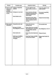
... damaged). Turn the adjuster to the lower position to decrease the pressure. Drive a nail into the injection port. Replace Nail Feeder (A) [112]. --- 24 --- While operating the nailer without nails, check if the driver blade is bent. Reassemble or replace. Do not use unspecified... if the adjuster is performed. Check Nail Feeder (A) [112] for abnormal condition. Replace the head valve spring. 2) Nails are bent when being driven. Check if the driver blade has returned. See item 1). After operating the nailer without nails, check if the driving operation is ...
... damaged). Turn the adjuster to the lower position to decrease the pressure. Drive a nail into the injection port. Replace Nail Feeder (A) [112]. --- 24 --- While operating the nailer without nails, check if the driver blade is bent. Reassemble or replace. Do not use unspecified... if the adjuster is performed. Check Nail Feeder (A) [112] for abnormal condition. Replace the head valve spring. 2) Nails are bent when being driven. Check if the driver blade has returned. See item 1). After operating the nailer without nails, check if the driving operation is ...
Service Manual
Page 28
... the nailer without nails and check if the driver blade is very hard. Do not use unspecified workpieces. Driver blade worn. Check if they move smoothly after putting nails, and check if the nail feeder operates smoothly. See in item 1). Use specified nails. mechanism... nails are specified ones. Remedy Adjust the adjuster to the lowest position and drive a nail. Inspection method Turn the adjuster to the proper position. Replace the driver blade. 4) Nails clog the Unspecified nails used. Nail Feeder (A) [112] is improperly adjusted. Problem Possible cause 3) Head of a nail ...
... the nailer without nails and check if the driver blade is very hard. Do not use unspecified workpieces. Driver blade worn. Check if they move smoothly after putting nails, and check if the nail feeder operates smoothly. See in item 1). Use specified nails. mechanism... nails are specified ones. Remedy Adjust the adjuster to the lowest position and drive a nail. Inspection method Turn the adjuster to the proper position. Replace the driver blade. 4) Nails clog the Unspecified nails used. Nail Feeder (A) [112] is improperly adjusted. Problem Possible cause 3) Head of a nail ...
Service Manual
Page 29
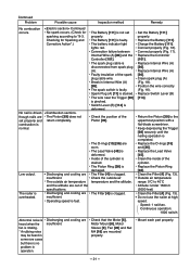
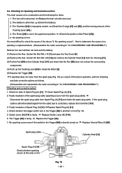
... and take corrective actions as follows. (Disassemble and reassemble the nailer according to check the cause of no combustion are the following ... of Spark Plug (A) [11]. Spark plug cable Cylinder Head [14] Spark Plug (A) [11] Check whether sparking ...the Trigger [98] is explained below. (Disassemble the nailer according to scratches), replace the Controller [101]. 3. No... Bolt M5 x 20 [13] and remove the Cylinder Head [14] from the cable due to "10. Faulty insulation of the Pushing ...Lever (B) [114] is directly turned on the Cylinder Head [14] and check that the Fan [20] does...
... and take corrective actions as follows. (Disassemble and reassemble the nailer according to check the cause of no combustion are the following ... of Spark Plug (A) [11]. Spark plug cable Cylinder Head [14] Spark Plug (A) [11] Check whether sparking ...the Trigger [98] is explained below. (Disassemble the nailer according to scratches), replace the Controller [101]. 3. No... Bolt M5 x 20 [13] and remove the Cylinder Head [14] from the cable due to "10. Faulty insulation of the Pushing ...Lever (B) [114] is directly turned on the Cylinder Head [14] and check that the Fan [20] does...
Service Manual
Page 31
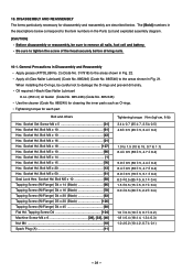
...the Parts List and exploded assembly diagram. [CAUTION] Before disassembly or reassembly, be careful not to the item numbers in Fig. 21. Oil required: Hitachi Gas Nailer Lubricant 8 oz. (250 cc) oil feeder (Code No. 885-246) (Code No. 885-546) Use the cleaner (Code No. 885245) for...50 51] Seal Lock Hex. General Precautions in Disassembly and Reassembly Apply grease (ATTOLUB No. 2) (Code No. 317918) to tighten the screw of the head securely before driving nails. 10-1. Tapping Screw D4 104] Machine Screw M4 x 6 28], [33], [46] Nut M4 18] Spark Plug (A 11] Tightening torque N•...
...the Parts List and exploded assembly diagram. [CAUTION] Before disassembly or reassembly, be careful not to the item numbers in Fig. 21. Oil required: Hitachi Gas Nailer Lubricant 8 oz. (250 cc) oil feeder (Code No. 885-246) (Code No. 885-546) Use the cleaner (Code No. 885245) for...50 51] Seal Lock Hex. General Precautions in Disassembly and Reassembly Apply grease (ATTOLUB No. 2) (Code No. 317918) to tighten the screw of the head securely before driving nails. 10-1. Tapping Screw D4 104] Machine Screw M4 x 6 28], [33], [46] Nut M4 18] Spark Plug (A 11] Tightening torque N•...


