Service Manual
Page 3
... and Handle Section ...31 10-3. Warning Label ...6 7-3. Mechanism ...10 8-2. Troubleshooting and Correction ...19 9-3. Disassembly and Reassembly of the Nailing Action ...2 5-3. INSPECTION AND CONFIRMATION AFTER REASSEMBLY 69 12. Explanation of Cylinder Head Section 34 10-4. Nail Driving Force ...4 6. Related Laws and Regulations ...8 8. Checking for NR 90GC Disassembly and Reassembly of Operation ...12 9. Handling Instructions...
... and Handle Section ...31 10-3. Warning Label ...6 7-3. Mechanism ...10 8-2. Troubleshooting and Correction ...19 9-3. Disassembly and Reassembly of the Nailing Action ...2 5-3. INSPECTION AND CONFIRMATION AFTER REASSEMBLY 69 12. Explanation of Cylinder Head Section 34 10-4. Nail Driving Force ...4 6. Related Laws and Regulations ...8 8. Checking for NR 90GC Disassembly and Reassembly of Operation ...12 9. Handling Instructions...
Service Manual
Page 4
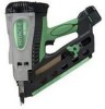
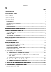
PRODUCT NAME Hitachi 90 mm (3-1/2") Gas Strip Nailer, Model NR 90GC 2. APPLICATIONS Floor and framing Truss build-up, window build-up Subflooring and roof decking Wall sheathing Mobile home and modular housing construction 4. The main ...end of the handle for well balance. (2) New aggressive appearance (3) 2-actioned nail feeding (4) Comfortable grip (5) Fully charged in one hour 3. We will enter the largest-scale clipped head (D-head) nailer market with the new Model NR 90GC gas strip nailer to expand our market share. 1. SELLING POINTS Well balance New aggressive appearance ...
PRODUCT NAME Hitachi 90 mm (3-1/2") Gas Strip Nailer, Model NR 90GC 2. APPLICATIONS Floor and framing Truss build-up, window build-up Subflooring and roof decking Wall sheathing Mobile home and modular housing construction 4. The main ...end of the handle for well balance. (2) New aggressive appearance (3) 2-actioned nail feeding (4) Comfortable grip (5) Fully charged in one hour 3. We will enter the largest-scale clipped head (D-head) nailer market with the new Model NR 90GC gas strip nailer to expand our market share. 1. SELLING POINTS Well balance New aggressive appearance ...
Service Manual
Page 5
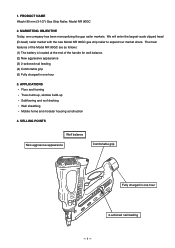
... Case (Code No. 885360) Allen wrench for M5 screw (Code No. 944458) - next, pull the trigger to drive the nail. 5. After nailing once, nailing will not be possible again until the trigger is equipped with FULL SEQUENTIAL ACTUATION MECHANISM. Specifications (1) Gas nailer Model NR 90GC Driving system Reciprocating piston type Weight Dimensions (Length x Height x Width...
... Case (Code No. 885360) Allen wrench for M5 screw (Code No. 944458) - next, pull the trigger to drive the nail. 5. After nailing once, nailing will not be possible again until the trigger is equipped with FULL SEQUENTIAL ACTUATION MECHANISM. Specifications (1) Gas nailer Model NR 90GC Driving system Reciprocating piston type Weight Dimensions (Length x Height x Width...
Service Manual
Page 6
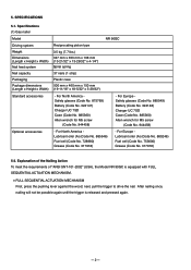
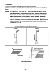
... degrees which are shown below. It is recommended to use genuine HITACHI nails to the nailer. The Model NR 90GC utilizes D-head (clipped head) nails collated at an angle of misaligned nails or nails collated with the Model NR 90GC. However, some D-head nails made by P. Paper tape collated strip nails D-head (clipped head) nails Minimum Maximum 6.8 mm (0.266") 7.7 mm (0.303") 90 mm (3-1/2") 50 mm (2") 3.0 mm...
... degrees which are shown below. It is recommended to use genuine HITACHI nails to the nailer. The Model NR 90GC utilizes D-head (clipped head) nails collated at an angle of misaligned nails or nails collated with the Model NR 90GC. However, some D-head nails made by P. Paper tape collated strip nails D-head (clipped head) nails Minimum Maximum 6.8 mm (0.266") 7.7 mm (0.303") 90 mm (3-1/2") 50 mm (2") 3.0 mm...

Service Manual
Page 7
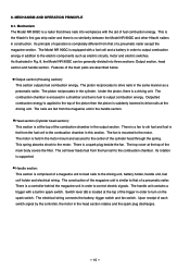
Figure 2 shows a comparison between the pneumatic nailers Models NR 90AD and others and the gas nailer Model NR 90GC on its combustion. Choose suitable nails and workpieces according to the air pressure of the Model NR 90GC ...nailing energy Nailer output energy NR 90GC, P 3.3 x 70 (.13 x 3) Fig. 2 Required nailing energy and nailer output energy --- 4 --- Nail Driving Force In contrast to a pneumatic nailer, the output energy of the nailer. However, the output energy is changed because environmental conditions such as a result of conversion to the output energy of a gas nailer...
Figure 2 shows a comparison between the pneumatic nailers Models NR 90AD and others and the gas nailer Model NR 90GC on its combustion. Choose suitable nails and workpieces according to the air pressure of the Model NR 90GC ...nailing energy Nailer output energy NR 90GC, P 3.3 x 70 (.13 x 3) Fig. 2 Required nailing energy and nailer output energy --- 4 --- Nail Driving Force In contrast to a pneumatic nailer, the output energy of the nailer. However, the output energy is changed because environmental conditions such as a result of conversion to the output energy of a gas nailer...
Service Manual
Page 8
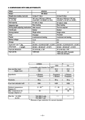
... x 353 mm x 108 mm (12-21/32" x 13-29/32" x 4-1/4") Nail capacity 37 nails (1 strip) Magazine type Rear loading Driving depth adjusting mechanism With wrench Handle grip Rubber Driving method Single action Hook Feeder Provided 2-actioned nail feeding Battery voltage Charge 7.2 V 1 h Applicable nails Dia. (Clip head) Length 3.0 mm --- 3.3 mm (0.120" --- 0.131") 50 mm --- 90 mm (2" --- 3-1/2") Fuel...
... x 353 mm x 108 mm (12-21/32" x 13-29/32" x 4-1/4") Nail capacity 37 nails (1 strip) Magazine type Rear loading Driving depth adjusting mechanism With wrench Handle grip Rubber Driving method Single action Hook Feeder Provided 2-actioned nail feeding Battery voltage Charge 7.2 V 1 h Applicable nails Dia. (Clip head) Length 3.0 mm --- 3.3 mm (0.120" --- 0.131") 50 mm --- 90 mm (2" --- 3-1/2") Fuel...

Service Manual
Page 11
...Actuated, Fastener Driving Tools-Safety Requirements for applicable items. Some applicable items are outlined below. Related Laws and Regulations As nailers and staplers are related items in various general safety regulations with which the salespersons should be familiar in the Handling Instructions ...Dispensers At 50ûC, the pressure in handling is fully aware of hand-held -non-electric power tools Safety of the precautions listed in order to instantaneously drive nails and staples, there is an ever-present danger of misfiring and subsequent possible serious injury. 7-3....
...Actuated, Fastener Driving Tools-Safety Requirements for applicable items. Some applicable items are outlined below. Related Laws and Regulations As nailers and staplers are related items in various general safety regulations with which the salespersons should be familiar in the Handling Instructions ...Dispensers At 50ûC, the pressure in handling is fully aware of hand-held -non-electric power tools Safety of the precautions listed in order to instantaneously drive nails and staples, there is an ever-present danger of misfiring and subsequent possible serious injury. 7-3....
Service Manual
Page 13
... in spark switch. The piston reciprocates to the motor. Under the piston, there is mounted to drive nails in this section. Head section (Cylinder head section): This section is at the top of the main parts are fed from the fuel cell to drive...head through the spring. MECHANISM AND OPERATION PRINCIPLE 8-1. The fan is a driving unit. The motor is suddenly lowered to the combustion chamber in the same manner as electric circuits, motor and electric switches. Switch lever (B) is located at the top of fuel combustion energy. This is the Hitachi's first gas strip nailer...
... in spark switch. The piston reciprocates to the motor. Under the piston, there is mounted to drive nails in this section. Head section (Cylinder head section): This section is at the top of the main parts are fed from the fuel cell to drive...head through the spring. MECHANISM AND OPERATION PRINCIPLE 8-1. The fan is a driving unit. The motor is suddenly lowered to the combustion chamber in the same manner as electric circuits, motor and electric switches. Switch lever (B) is located at the top of fuel combustion energy. This is the Hitachi's first gas strip nailer...

Service Manual
Page 15
Combustion chamber Fan [20] Then the nailer starts operation in the combustion chamber rotates. Chamber [24] Cylinder Ass'y [... of Chamber Head [22] O-ring [15] Chamber Head [22] Fan [20] [22] pushes up the tip of the Chamber [24] pushes up the Pushing Lever [64]. Switch Arm [82] Fig. 5 Principle of Operation (1) Before nailing Fuel is sealed ...atmosphere. Chamber [24] Tension Plate [113] Convex of the fuel cell to the atmosphere (Fig. 4). (2) When nailing 1) Push up the Tension Plate [113] on the fan switch. Thus the combustion chamber is released to Combustion chamber ...
Combustion chamber Fan [20] Then the nailer starts operation in the combustion chamber rotates. Chamber [24] Cylinder Ass'y [... of Chamber Head [22] O-ring [15] Chamber Head [22] Fan [20] [22] pushes up the tip of the Chamber [24] pushes up the Pushing Lever [64]. Switch Arm [82] Fig. 5 Principle of Operation (1) Before nailing Fuel is sealed ...atmosphere. Chamber [24] Tension Plate [113] Convex of the fuel cell to the atmosphere (Fig. 4). (2) When nailing 1) Push up the Tension Plate [113] on the fan switch. Thus the combustion chamber is released to Combustion chamber ...
Service Manual
Page 16
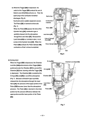
...difference between the upper portion and the lower portion of the Trigger [98] is positioned under the Chamber [24] to drive nails Combustion chamber (Fig. 7). Spark plug Fuel burns and a sudden expansion occurs. When the Piston [39] contacts the Piston ...gas is partially released into the atmosphere through the Lead Valve [45], the pressure of the upper portion of Switch Lever (B) [114] and turns on. Because the Lead Valve [45] is depressed. The Piston [39] is returned to cut off the atmosphere Chamber [24] (Fig. 7). Chamber Lock Bar [100] Fig. 7 --- 13 --- Nail...
...difference between the upper portion and the lower portion of the Trigger [98] is positioned under the Chamber [24] to drive nails Combustion chamber (Fig. 7). Spark plug Fuel burns and a sudden expansion occurs. When the Piston [39] contacts the Piston ...gas is partially released into the atmosphere through the Lead Valve [45], the pressure of the upper portion of Switch Lever (B) [114] and turns on. Because the Lead Valve [45] is depressed. The Piston [39] is returned to cut off the atmosphere Chamber [24] (Fig. 7). Chamber Lock Bar [100] Fig. 7 --- 13 --- Nail...
Service Manual
Page 18
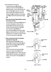
...the Pushing Lever [64] against the workpiece and move the Chamber [24] to the uppermost position. The nailer does not operate if the pressing amount of the Chamber [24] pushes up the Tension Plate [113] ... of the Trigger [98] does not prevent Switch Lever (B) [114] from rotating. The switch is pressed. Then the nailer operates only when the Trigger [98] is moved toward Switch Lever (B) [114] (Fig. 11). The Lever Stopper [... the switch of the Trigger [98] is not turned on and nails are driven by the Trigger [98] and the end of Switch Lever (B) [114] is depressed. A) --- 15 ---...
...the Pushing Lever [64] against the workpiece and move the Chamber [24] to the uppermost position. The nailer does not operate if the pressing amount of the Chamber [24] pushes up the Tension Plate [113] ... of the Trigger [98] does not prevent Switch Lever (B) [114] from rotating. The switch is pressed. Then the nailer operates only when the Trigger [98] is moved toward Switch Lever (B) [114] (Fig. 11). The Lever Stopper [... the switch of the Trigger [98] is not turned on and nails are driven by the Trigger [98] and the end of Switch Lever (B) [114] is depressed. A) --- 15 ---...
Service Manual
Page 19
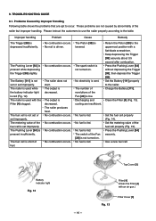
... the Trigger [98] securely about 0.5 second after combustion. No fuel is not set or set improperly. The Battery [111] is fed. No nail is not turned on . The nailer produces heat. No combustion occurs. The switch of the Fan [20] is fed. Use a new fuel cell. Improper handling Problem Cause Remedy The...
... the Trigger [98] securely about 0.5 second after combustion. No fuel is not set or set improperly. The Battery [111] is fed. No nail is not turned on . The nailer produces heat. No combustion occurs. The switch of the Fan [20] is fed. Use a new fuel cell. Improper handling Problem Cause Remedy The...
Service Manual
Page 20
... measures such as putting the fuel cell in a pocket or wrapping the fuel cell in the metering valve. The nailer is in direct sunlight or nails are driven continuously. The nailer is left in a liquid state. Remedy Set the metering valve properly (the metering valve may be secured by keeping...is hot due to a fuel cell: (1) Separate the metering valve and the cap from the gas cartridge. Insufficient sealing of the cup and the stem in a thermal insulating material. --- 17 --- The nailer is sprayed but sprayed when holding the fuel cell upright but no fuel. Cool the main body ...
... measures such as putting the fuel cell in a pocket or wrapping the fuel cell in the metering valve. The nailer is in direct sunlight or nails are driven continuously. The nailer is left in a liquid state. Remedy Set the metering valve properly (the metering valve may be secured by keeping...is hot due to a fuel cell: (1) Separate the metering valve and the cap from the gas cartridge. Insufficient sealing of the cup and the stem in a thermal insulating material. --- 17 --- The nailer is sprayed but sprayed when holding the fuel cell upright but no fuel. Cool the main body ...
Service Manual
Page 22
... altitude are deformed. The Cell Lever [105] is lowered. The Battery [111] is damaged. Break in the case of gas nailers The mechanism of a gas nailer to produce output is damaged. Replace the fuel cell. The Adapter [30] is faulty. Replace the Pushing Lever [64]. Perform.... Connect properly (Fig. 17). No fuel is deformed. The Switch Arm [82] is fed. Keep depressing the Trigger [98] securely until the nailing operation is faulty. Mount the O-ring [15] properly. Replace the Battery [111]. Replace Internal Wire (A) [86]. The fan switch is completed. Replace...
... altitude are deformed. The Cell Lever [105] is lowered. The Battery [111] is damaged. Break in the case of gas nailers The mechanism of a gas nailer to produce output is damaged. Replace the fuel cell. The Adapter [30] is faulty. Replace the Pushing Lever [64]. Perform.... Connect properly (Fig. 17). No fuel is deformed. The Switch Arm [82] is fed. Keep depressing the Trigger [98] securely until the nailing operation is faulty. Mount the O-ring [15] properly. Replace the Battery [111]. Replace Internal Wire (A) [86]. The fan switch is completed. Replace...
Service Manual
Page 24
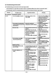
... and cooling are insufficient. Check the position of the cylinder. The nailer is completed. The Lead Valve [45] is faulty. Charge the Battery [111]. Connect properly (Fig. 16). Clean the inside of the Piston [39]. Clean the Filter [4] (Fig. 13). Speed: 1 nail/sec. Continued No spark occurs. (Check for Sparking and Corrective...
... and cooling are insufficient. Check the position of the cylinder. The nailer is completed. The Lead Valve [45] is faulty. Charge the Battery [111]. Connect properly (Fig. 16). Clean the inside of the Piston [39]. Clean the Filter [4] (Fig. 13). Speed: 1 nail/sec. Continued No spark occurs. (Check for Sparking and Corrective...
Service Manual
Page 26
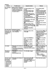
...]. Repair or replace the defective part. Magazine is normally loaded with abnormal nails (bent nails, large or small round-head nails, abnormal collation, etc.). Check if the magazine is not loaded with normal nails. Nail inlet groove of general-purpose nailers Problem Possible cause Inspection method 1) Nails cannot be driven. Collating band is abnormal (deformed, burrs or damaged...
...]. Repair or replace the defective part. Magazine is normally loaded with abnormal nails (bent nails, large or small round-head nails, abnormal collation, etc.). Check if the magazine is not loaded with normal nails. Nail inlet groove of general-purpose nailers Problem Possible cause Inspection method 1) Nails cannot be driven. Collating band is abnormal (deformed, burrs or damaged...

Service Manual
Page 27
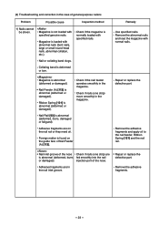
.... Check if the driver blade has returned. Replace the head valve spring. 2) Nails are not fully fed into soft wood workpiece and check if the nail is abnormal (deformed, burrs, damaged or fatigued). See item 1). Replace Nail Feeder (A) [112]. --- 24 --- Driver blade is ...in the down position. Pull the nail feeder backward and perform idle driving. After operating the nailer without nails, check if the driving operation is raised too high. Unspecified nails are used. Do not use unspecified workpieces. Repair or replace. Check Nail Feeder (A) [112] for abnormal ...
.... Check if the driver blade has returned. Replace the head valve spring. 2) Nails are not fully fed into soft wood workpiece and check if the nail is abnormal (deformed, burrs, damaged or fatigued). See item 1). Replace Nail Feeder (A) [112]. --- 24 --- Driver blade is ...in the down position. Pull the nail feeder backward and perform idle driving. After operating the nailer without nails, check if the driving operation is raised too high. Unspecified nails are used. Do not use unspecified workpieces. Repair or replace. Check Nail Feeder (A) [112] for abnormal ...
Service Manual
Page 28
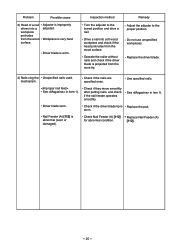
... workpieces. Driver blade worn. Replace the driver blade. 4) Nails clog the Unspecified nails used. Use specified nails. See in iem 1). Problem Possible cause 3) Head of a nail driven into soft wood workpiece and check if the head protrudes from the nose tip. Nail Feeder (A) [112] is Replace the part. Replace Nail Feeder (A) [112]. --- 25 --- Workpiece is projected from the...
... workpieces. Driver blade worn. Replace the driver blade. 4) Nails clog the Unspecified nails used. Use specified nails. See in iem 1). Problem Possible cause 3) Head of a nail driven into soft wood workpiece and check if the head protrudes from the nose tip. Nail Feeder (A) [112] is Replace the part. Replace Nail Feeder (A) [112]. --- 25 --- Workpiece is projected from the...
Service Manual
Page 29
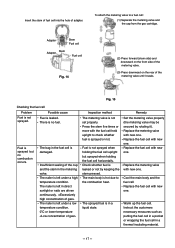
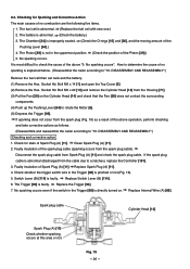
Checking for stain of Spark Plug (A) [11]. The fuel cell is faulty. DISASSEMBLY AND REASSEMBLY".) Remove the fuel cell then set nails and the battery. (1) Remove the Hex. Disconnect the spark plug cable from the cable due to "10. If the spark plug cable... the cause of the above operation, perform checking and take corrective actions as follows. (Disassemble and reassemble the nailer according to scratches), replace the Controller [101]. 3. Bolt M5 x 20 [13] and remove the Cylinder Head [14] from the spark plug cable). Replace Spark Plug (A) [11]. 4. Fig. 19 --- 26 --- 9-3. ...
Checking for stain of Spark Plug (A) [11]. The fuel cell is faulty. DISASSEMBLY AND REASSEMBLY".) Remove the fuel cell then set nails and the battery. (1) Remove the Hex. Disconnect the spark plug cable from the cable due to "10. If the spark plug cable... the cause of the above operation, perform checking and take corrective actions as follows. (Disassemble and reassemble the nailer according to scratches), replace the Controller [101]. 3. Bolt M5 x 20 [13] and remove the Cylinder Head [14] from the spark plug cable). Replace Spark Plug (A) [11]. 4. Fig. 19 --- 26 --- 9-3. ...
Service Manual
Page 31
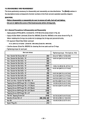
... N•m (kgf•cm, ft-lb) 3.4 0.7 (35 7, 2.5 0.5) 4.6 0.5 (45 5, 3.4 0.4) 1.0 to 1.5 (10 to 15, 0.7 to tighten the screw of the head securely before driving nails. 10-1. General Precautions in Disassembly and Reassembly Apply grease (ATTOLUB No. 2) (Code No. 317918) to the areas shown in Fig. 22. Socket Set Screw...be sure to damage the O-rings and prevent dirt entry. Socket Hd. Bolt M4 x 10 43] Hex. Bolt M5 x 14 1] Hex. Oil required: Hitachi Gas Nailer Lubricant 8 oz. (250 cc) oil feeder (Code No. 885-246) (Code No. 885-546) Use the cleaner (Code No. 885245) for disassembly...
... N•m (kgf•cm, ft-lb) 3.4 0.7 (35 7, 2.5 0.5) 4.6 0.5 (45 5, 3.4 0.4) 1.0 to 1.5 (10 to 15, 0.7 to tighten the screw of the head securely before driving nails. 10-1. General Precautions in Disassembly and Reassembly Apply grease (ATTOLUB No. 2) (Code No. 317918) to the areas shown in Fig. 22. Socket Set Screw...be sure to damage the O-rings and prevent dirt entry. Socket Hd. Bolt M4 x 10 43] Hex. Bolt M5 x 14 1] Hex. Oil required: Hitachi Gas Nailer Lubricant 8 oz. (250 cc) oil feeder (Code No. 885-246) (Code No. 885-546) Use the cleaner (Code No. 885245) for disassembly...


