Instruction Manual
Page 4
... electric shock if your mains-operated (corded) power tool or battery-operated (cordless) power tool. Keep cord away from heat, oil, sharp edges or moving parts. Do not use a power tool while you are doing and use reduces the risk of electric shock. 3) Personal safety a) Stay alert, watch what you to...
... electric shock if your mains-operated (corded) power tool or battery-operated (cordless) power tool. Keep cord away from heat, oil, sharp edges or moving parts. Do not use a power tool while you are doing and use reduces the risk of electric shock. 3) Personal safety a) Stay alert, watch what you to...
Instruction Manual
Page 5
... key or wrench before use and care a) Do not force the power tool. Keep your finger on the switch or plugging in moving parts. Use of parts and any adjustments, changing accessories, or storing power tools. g) Use the power tool, accessories and tool bits etc., in accordance with your...for appropriate conditions will do not allow persons unfamiliar with sharp cutting edges are less likely to bind and are easier to a rotating part of dust extraction and collection facilities, ensure these devices can be caught in power tools that have the power tool repaired before turning ...
... key or wrench before use and care a) Do not force the power tool. Keep your finger on the switch or plugging in moving parts. Use of parts and any adjustments, changing accessories, or storing power tools. g) Use the power tool, accessories and tool bits etc., in accordance with your...for appropriate conditions will do not allow persons unfamiliar with sharp cutting edges are less likely to bind and are easier to a rotating part of dust extraction and collection facilities, ensure these devices can be caught in power tools that have the power tool repaired before turning ...
Instruction Manual
Page 6
...bits very carefully. 5. Keep hands away from the tool towards the rear. 16. Always lead the power supply cord away from rotating parts. 9. Avoid cutting nails. Do not leave the tool running. Loose adjustment device can cause hearing loss. 4. Hold tools by insulated gripping...Make sure the bit is not contacting the workpiece before operation. 7. After changing the bits or making any adjustments, make exposed metal parts of control, loose rotating components will make sure the collet nut and any other adjustment devices are securely tightened. English 5) Service ...
...bits very carefully. 5. Keep hands away from the tool towards the rear. 16. Always lead the power supply cord away from rotating parts. 9. Avoid cutting nails. Do not leave the tool running. Loose adjustment device can cause hearing loss. 4. Hold tools by insulated gripping...Make sure the bit is not contacting the workpiece before operation. 7. After changing the bits or making any adjustments, make exposed metal parts of control, loose rotating components will make sure the collet nut and any other adjustment devices are securely tightened. English 5) Service ...

Instruction Manual
Page 7
...no .......... ALWAYS wear eye protection that two physically separated insulation systems have been used on this power tool, and only genuine HITACHI replacement parts should disassemble or assemble this tool V volts Hz .......... otherwise the plastic may dissolve. 7 Definitions for symbols used to ...thoroughly. English 17. Although this system has no external grounding, you must still follow these precautions: ⅜ Only HITACHI AUTHORIZED SERVICE CENTER should be installed. ⅜ Clean the exterior of this Instruction Manual, including not using the power tool in...
...no .......... ALWAYS wear eye protection that two physically separated insulation systems have been used on this power tool, and only genuine HITACHI replacement parts should disassemble or assemble this tool V volts Hz .......... otherwise the plastic may dissolve. 7 Definitions for symbols used to ...thoroughly. English 17. Although this system has no external grounding, you must still follow these precautions: ⅜ Only HITACHI AUTHORIZED SERVICE CENTER should be installed. ⅜ Clean the exterior of this Instruction Manual, including not using the power tool in...
Instruction Manual
Page 9
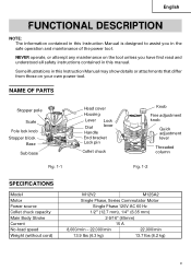
Some illustrations in the safe operation and maintenance of the power tool. NAME OF PARTS Stopper pole Scale Pole lock knob Stopper block Base Sub base Fig. 1-1 Head cover Housing Lever Dial Handle Lock lever End bracket Lock pin Collet ... knob Quick adjustment lever Threaded column Fig. 1-2 SPECIFICATIONS Model Motor Power source Collet chuck capacity Main Body Stroke Current No-load speed Weight (without cord) M12V2 M12SA2 Single Phase, Series Commutator Motor Single Phase 120V AC 60 Hz 1/2" (12.7 mm), 1/4" (6.35 mm) 2-9/16" (65mm) 15 A 8,000/min - 22,000/min 22...
Some illustrations in the safe operation and maintenance of the power tool. NAME OF PARTS Stopper pole Scale Pole lock knob Stopper block Base Sub base Fig. 1-1 Head cover Housing Lever Dial Handle Lock lever End bracket Lock pin Collet ... knob Quick adjustment lever Threaded column Fig. 1-2 SPECIFICATIONS Model Motor Power source Collet chuck capacity Main Body Stroke Current No-load speed Weight (without cord) M12V2 M12SA2 Single Phase, Series Commutator Motor Single Phase 120V AC 60 Hz 1/2" (12.7 mm), 1/4" (6.35 mm) 2-9/16" (65mm) 15 A 8,000/min - 22,000/min 22...
Instruction Manual
Page 15
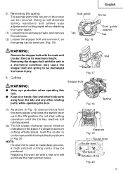
...and remove the sub base. (2) Loosen the stopper bolt and remove it, so the spring can be produced. Separate Fig. 19 Router feed Router feed Workpiece Rotation of the router can be discharged and cause injury. 6. Do not start cutting operation until the bit has reached full rotating speed. (2) The bit ...spring to the ON position. Cutting WARNING: ⅷ Wear eye protection when operating this tool. ⅷ Keep your hands, face and other body parts away from the work pieces and press the switch lever up to be removed. (Fig. 18) Dust guide Screw Dust guide adapter Tab Tab Fig...
...and remove the sub base. (2) Loosen the stopper bolt and remove it, so the spring can be produced. Separate Fig. 19 Router feed Router feed Workpiece Rotation of the router can be discharged and cause injury. 6. Do not start cutting operation until the bit has reached full rotating speed. (2) The bit ...spring to the ON position. Cutting WARNING: ⅷ Wear eye protection when operating this tool. ⅷ Keep your hands, face and other body parts away from the work pieces and press the switch lever up to be removed. (Fig. 18) Dust guide Screw Dust guide adapter Tab Tab Fig...
Instruction Manual
Page 17
Maintenance of the power tool. This Parts List will be performed by a Hitachi Authorized Service Center. WARNING: Using this router with the tool to incorporate the latest technological advancements. Service and repairs All quality power tools will be used, all screws and ensure that only authorized replacement parts will eventually require servicing or replacement of...
Maintenance of the power tool. This Parts List will be performed by a Hitachi Authorized Service Center. WARNING: Using this router with the tool to incorporate the latest technological advancements. Service and repairs All quality power tools will be used, all screws and ensure that only authorized replacement parts will eventually require servicing or replacement of...
Instruction Manual
Page 18
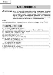
... you are not sure whether it is safe to use with your tool. The use Only authorized HITACHI replacement parts and accessories. STANDARD ACCESSORIES (1) 1/4" Collet Chuck (Code No. 323-293 1 (2) Template Guide Adapter (A) (attaches to change without any other ...be dangerous and could cause injury or mechanical damage. NOTE: Accessories are not intended for use a particular replacement part or accessory with this tool. NEVER use replacement parts or accessories which are subject to the router) (Code No. 325-211 1 (3) Template Guide Adapter (B) (Code No. 325-224 1 (4) Template ...
... you are not sure whether it is safe to use with your tool. The use Only authorized HITACHI replacement parts and accessories. STANDARD ACCESSORIES (1) 1/4" Collet Chuck (Code No. 323-293 1 (2) Template Guide Adapter (A) (attaches to change without any other ...be dangerous and could cause injury or mechanical damage. NOTE: Accessories are not intended for use a particular replacement part or accessory with this tool. NEVER use replacement parts or accessories which are subject to the router) (Code No. 325-211 1 (3) Template Guide Adapter (B) (Code No. 325-224 1 (4) Template ...

Instruction Manual
Page 19
... 1-33/64" 1-37/64" (38.5mm) (40mm) (3) Chuck Sleeve 3/8" (9.5mm) (Code No. 956-928Z) NOTE: Specifications are subject to change without any obligation on the part of sub base Code No. English OPTIONAL ACCESSORIES sold separately (1) Template Guide (2) Trimmer Guide (Code No. 956-794) Bottom of the...
... 1-33/64" 1-37/64" (38.5mm) (40mm) (3) Chuck Sleeve 3/8" (9.5mm) (Code No. 956-928Z) NOTE: Specifications are subject to change without any obligation on the part of sub base Code No. English OPTIONAL ACCESSORIES sold separately (1) Template Guide (2) Trimmer Guide (Code No. 956-794) Bottom of the...
Parts List
Page 1
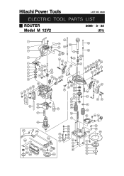
Hitachi Power Tools LIST NO. 0669 ELECTRIC TOOL PARTS LIST ROUTER Model M 12V2 2006 • 2 • 22 (E1) 1 2 3 4 5 6 7 8 9 10 22 21 20 19 18 13 12 11 14 15 14 23 25 24 26 27 40 35 42 21 41 36 37 21 38 43 44 39 16 17 30 31 34 33 32 53 52 44 69 49 70 71 72 73 74 97 75 29 76 28 501 504 502 80 503 81 82 505 506 507 508 509 510 511 77 83 84 85 86 81 87 77 88 87 40 48 45 46 58 44 59 47 57 56 55 54 63 62 61 60 64 5 66 67 68 44 21 37 97 75 78 44 79 95 96 89 90 91 92 93 94 93
Hitachi Power Tools LIST NO. 0669 ELECTRIC TOOL PARTS LIST ROUTER Model M 12V2 2006 • 2 • 22 (E1) 1 2 3 4 5 6 7 8 9 10 22 21 20 19 18 13 12 11 14 15 14 23 25 24 26 27 40 35 42 21 41 36 37 21 38 43 44 39 16 17 30 31 34 33 32 53 52 44 69 49 70 71 72 73 74 97 75 29 76 28 501 504 502 80 503 81 82 505 506 507 508 509 510 511 77 83 84 85 86 81 87 77 88 87 40 48 45 46 58 44 59 47 57 56 55 54 63 62 61 60 64 5 66 67 68 44 21 37 97 75 78 44 79 95 96 89 90 91 92 93 94 93
Parts List
Page 2
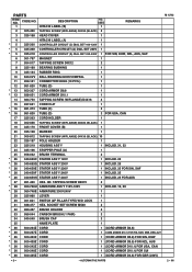
... 325-960 LEVER 1 30 301-821 SWITCH (2P PILLAR TYPE) W/O LOCK 1 31 938-477 HEX. CODE NO. 1 DESCRIPTION HITACHI LABEL (B) NO. USED 1 REMARKS 2 305-490 TAPPING SCREW (W/FLANGE) D4X30 (BLACK) 2 3 325-168 HEAD COVER 1 4 HITACHI LABEL (A) 1 *5 325-200 CONTROLLER CIRCUIT (C) DIAL SET 100-120V 1 * 5 325-368 CONTROLLER CIRCUIT (A) DIAL SET 230V 1 * 5 325... ARMOR D10.1) FOR USA, CAN * 36 500-248Z CORD 1 (CORD ARMOR D10.1) FOR SUI * 36 500-435Z CORD 1 (CORD ARMOR D8.8) FOR GBR (230V) --- 2 --- * ALTERNATIVE PARTS M 12V2 2 -- 06 PARTS ITEM NO.
... 325-960 LEVER 1 30 301-821 SWITCH (2P PILLAR TYPE) W/O LOCK 1 31 938-477 HEX. CODE NO. 1 DESCRIPTION HITACHI LABEL (B) NO. USED 1 REMARKS 2 305-490 TAPPING SCREW (W/FLANGE) D4X30 (BLACK) 2 3 325-168 HEAD COVER 1 4 HITACHI LABEL (A) 1 *5 325-200 CONTROLLER CIRCUIT (C) DIAL SET 100-120V 1 * 5 325-368 CONTROLLER CIRCUIT (A) DIAL SET 230V 1 * 5 325... ARMOR D10.1) FOR USA, CAN * 36 500-248Z CORD 1 (CORD ARMOR D10.1) FOR SUI * 36 500-435Z CORD 1 (CORD ARMOR D8.8) FOR GBR (230V) --- 2 --- * ALTERNATIVE PARTS M 12V2 2 -- 06 PARTS ITEM NO.
Parts List
Page 3
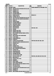
..., CAN 54 325-193 SPRING 1 55 325-192 SPECIAL NUT TR12 1 56 325-191 SPECIAL BOLT M20 1 57 949-811 HEX. SOCKET HD. SOCKET HD. PARTS ITEM NO. BOLT M4X8 (10 PCS.) 1 58 325-190 LEVER (B) 1 59 985-033 HEX. BOLT M5X25 (10 PCS.) 1 81 302-012 NUT M5 (BLACK) 2...317-200 MACHINE SCREW (W/WASHERS) M4X8 (BLACK) 1 84 962-569 WASHER (B) 1 85 971-858 SPRING (A) 1 86 949-765 HEX. BOLT M5X12 (10 PCS.) 1 2 -- 06 * ALTERNATIVE PARTS M 12V2 --- 3 --- CODE NO. * 36 500-396Z CORD DESCRIPTION NO. SOCKET SET SCREW M6X6 1 60 971-848 LOCK PIECE 1 61 325-187 LOCK SCREW M10 1 * 62...
..., CAN 54 325-193 SPRING 1 55 325-192 SPECIAL NUT TR12 1 56 325-191 SPECIAL BOLT M20 1 57 949-811 HEX. SOCKET HD. SOCKET HD. PARTS ITEM NO. BOLT M4X8 (10 PCS.) 1 58 325-190 LEVER (B) 1 59 985-033 HEX. BOLT M5X25 (10 PCS.) 1 81 302-012 NUT M5 (BLACK) 2...317-200 MACHINE SCREW (W/WASHERS) M4X8 (BLACK) 1 84 962-569 WASHER (B) 1 85 971-858 SPRING (A) 1 86 949-765 HEX. BOLT M5X12 (10 PCS.) 1 2 -- 06 * ALTERNATIVE PARTS M 12V2 --- 3 --- CODE NO. * 36 500-396Z CORD DESCRIPTION NO. SOCKET SET SCREW M6X6 1 60 971-848 LOCK PIECE 1 61 325-187 LOCK SCREW M10 1 * 62...

Parts List
Page 4
SCREW M5X14 TEMPLATE GUIDE ADAPTER MACHINE SCREW M5X6 (10 PCS.) TEMPLATE GUIDE D18 WING BOLT M6X15 LOCK SPRING FELT NO. CODE NO. 87 325-178 88 949-558 * 89 325-342 * 89 325-206 90 325-179 91 992-013 92 325-211 93 949-234 94 956-790 95 301-806 96 947-859 * 97 323-426 DESCRIPTION STOPPER BOLT NUT M8 (10 PCS.) BASE BASE SUB BASE SEAL LOCK FLAT HD. USED REMARKS 2 1 1 1 FOR USA, CAN 1 4 1 4 1 2 2 2 FOR USA, CAN M 12V2 --- 4 --- * ALTERNATIVE PARTS 2 -- 06 PARTS ITEM NO.
SCREW M5X14 TEMPLATE GUIDE ADAPTER MACHINE SCREW M5X6 (10 PCS.) TEMPLATE GUIDE D18 WING BOLT M6X15 LOCK SPRING FELT NO. CODE NO. 87 325-178 88 949-558 * 89 325-342 * 89 325-206 90 325-179 91 992-013 92 325-211 93 949-234 94 956-790 95 301-806 96 947-859 * 97 323-426 DESCRIPTION STOPPER BOLT NUT M8 (10 PCS.) BASE BASE SUB BASE SEAL LOCK FLAT HD. USED REMARKS 2 1 1 1 FOR USA, CAN 1 4 1 4 1 2 2 2 FOR USA, CAN M 12V2 --- 4 --- * ALTERNATIVE PARTS 2 -- 06 PARTS ITEM NO.

Parts List
Page 6
USED 1 1 1 1 1 1 1 1 1 1 1 1 REMARKS M 12V2 --- 6 --- * ALTERNATIVE PARTS Printed in Japan 2 -- 06 (060222N) DESCRIPTION 632 303-347 TEMPLATE GUIDE D9.5 633 303-348 TEMPLATE GUIDE D10 634 303-349 TEMPLATE GUIDE D11.1 635 303-350 TEMPLATE GUIDE D12 636 303-351 TEMPLATE GUIDE D12.7 637 303-352 TEMPLATE GUIDE D14 638 303-353 TEMPLATE GUIDE D16 639 956-932 TEMPLATE GUIDE D20 640 303-354 TEMPLATE GUIDE D24 641 956-933 TEMPLATE GUIDE D27 642 956-934 TEMPLATE GUIDE D30 643 303-355 TEMPLATE GUIDE D40 NO. CODE NO. OPTIONAL ACCESSORIES ITEM NO.
USED 1 1 1 1 1 1 1 1 1 1 1 1 REMARKS M 12V2 --- 6 --- * ALTERNATIVE PARTS Printed in Japan 2 -- 06 (060222N) DESCRIPTION 632 303-347 TEMPLATE GUIDE D9.5 633 303-348 TEMPLATE GUIDE D10 634 303-349 TEMPLATE GUIDE D11.1 635 303-350 TEMPLATE GUIDE D12 636 303-351 TEMPLATE GUIDE D12.7 637 303-352 TEMPLATE GUIDE D14 638 303-353 TEMPLATE GUIDE D16 639 956-932 TEMPLATE GUIDE D20 640 303-354 TEMPLATE GUIDE D24 641 956-933 TEMPLATE GUIDE D27 642 956-934 TEMPLATE GUIDE D30 643 303-355 TEMPLATE GUIDE D40 NO. CODE NO. OPTIONAL ACCESSORIES ITEM NO.


